Language selection

Search

Patent 2440566 Summary

Third-party information liability

Some of the information on this Web page has been provided by external sources. The Government of Canada is not responsible for the accuracy, reliability or currency of the information supplied by external sources. Users wishing to rely upon this information should consult directly with the source of the information. Content provided by external sources is not subject to official languages, privacy and accessibility requirements.

Claims and Abstract availability

Any discrepancies in the text and image of the Claims and Abstract are due to differing posting times. Text of the Claims and Abstract are posted:

  • At the time the application is open to public inspection;
  • At the time of issue of the patent (grant).
(12) Patent: (11) CA 2440566
(54) English Title: SPINDLE FOR A DOOR HANDLE ASSEMBLY
(54) French Title: AXE POUR POIGNEE DE PORTE
Status: Deemed expired
Bibliographic Data
(51) International Patent Classification (IPC):
  • E05B 15/00 (2006.01)
  • E05B 1/00 (2006.01)
(72) Inventors :
  • WALLS, CHRISTOPHER G. (United States of America)
  • REEVES, STANLEY R. (United States of America)
(73) Owners :
  • NEWELL OPERATING COMPANY (United States of America)
(71) Applicants :
  • NEWELL OPERATING COMPANY (United States of America)
(74) Agent: GOWLING WLG (CANADA) LLP
(74) Associate agent:
(45) Issued: 2008-04-29
(22) Filed Date: 2003-09-10
(41) Open to Public Inspection: 2004-03-11
Examination requested: 2003-09-30
Availability of licence: N/A
(25) Language of filing: English

Patent Cooperation Treaty (PCT): No

(30) Application Priority Data:
Application No. Country/Territory Date
60/409,784 United States of America 2002-09-11

Abstracts

English Abstract

A spindle for a door assembly includes a first member and a second member. The first and second members each have a base, a first leg and a second leg extending from the base. The second leg is recessed relative to the first leg. The first member confronts the second member such that the first leg of the first member confronts the second leg of the second member and the second leg of the first member confronts the first leg of the second member forming the spindle.


French Abstract

Un axe pour un ensemble de portes comprenant un premier élément et un second élément. Les premier et second éléments ont chacun une base, une première branche et une seconde branche s'étendant à partir de la base. La seconde branche est en retrait par rapport à la première branche. Le premier élément fait face au deuxième élément de telle sorte que la première branche du premier élément fait face à la seconde branche du second élément et la seconde branche du premier élément fait face à la première branche du second élément formant l'axe.

Claims

Note: Claims are shown in the official language in which they were submitted.


-8-


CLAIMS


What is claimed is:

1. A spindle for a door assembly comprising:
a first member having a base, a first leg extending from the base and a second
leg
extending from the base, and a semi-circular cavity defining a first tapered
portion in the first leg, a second tapered portion in the second leg and a
thin
section in the base; and,
a second member having a base, a first leg extending from the base and a
second leg
extending from the base, and a semi-circular cavity defining a first tapered
portion in the first leg, a second tapered portion in the second leg and a
thin
section in the base,
the first member confronting the second member wherein the first leg of the
first
member confronts the second leg of the second member and the second leg of
the first member confronts the first leg of the second member.
2. The spindle of claim 1, wherein the second leg of the first member is
recessed relative
to the first leg of the first member.
3. The spindle of claim 1, wherein the second leg of the second member is
recessed
relative to the first leg of the second member.
4. The spindle of claim 1, wherein the second leg of the first member is
recessed relative
to the first leg of the first member and the second leg of the second member
is recessed
relative to the first leg of the second member.
5. The spindle of claim 1, the first member confronting the second member
wherein the
first tapered portion of the first member confronts the second tapered portion
of the second leg
and the second tapered portion of the first member confronts the first tapered
portion of the
second member.
6. The spindle of claim 1, wherein the first leg of the first member includes
a first pillar
and the second leg of the first member includes a second pillar.
7. The spindle of claim 1, wherein the first leg of the second member includes
a first
pillar, and the second leg of the second member includes a second pillar.


-9-


8. The spindle of claim 1, wherein the first member and second member in
confronting
relationship cooperating first and second legs form a seam adapted to receive
a set screw for
fastening the spindle to a door handle.
9. A spindle for a door assembly, comprising:
a first member having a base and a first leg extending from the base and a
second leg
extending from the base, the second leg of the first member being recessed
relative to the first leg of the first member, the first leg of the first
member
including a first pillar and the second leg of the first member including a
second pillar; and,
a second member having a base and a first leg extending from the base and a
second
leg extending from the base, the second leg of the second member being
recessed relative to the first leg of the second member, and the first leg of
the
second member including a first pillar and the second leg of the second
member including a second pillar;
the first member confronting the second member wherein the first leg of the
first
member confronts the second leg of the second member and the second leg of
the first member confronts the first leg of the second member, and wherein the

first pillar of the first member confronts the second pillar of the second
member and the second pillar of the first member confronts the first pillar of

the second member.
10. The spindle of claim 9, the first member including a semi-circular cavity
defining a
first tapered portion in the first leg, a second tapered portion in the second
leg and a thin
section in the base, and,
the second member including a semi-circular cavity defining a first tapered
portion in
the first leg, a second tapered portion in the second leg and a thin section
in the
base,
the first member confronting the second member wherein the first tapered
portion of
the first member confronts the second tapered portion of the second leg and
the
second tapered portion of the first member confronts the first tapered portion

of the second member forming at least one thin outer wall having a seam.


-10-


11. The spindle of claim 9, wherein the first and second pillars of the first
member and
second member cooperatively form a bow to provide an interference fit with an
opening
formed in a door member.
12. A spindle for a door assembly comprising:
a first member comprising a base and a first leg extending from the base and a
second
leg extending from the base, the second leg being recessed relative to the
first
leg, the first member further comprising a semi-circular cavity defining a
first
tapered portion in the first leg, a second tapered portion in the second leg
and a
thin section in the base, the first leg of the first member includes a first
pillar,
the second leg of the first member includes a second pillar; and,
a second member having a base and a first leg extending from the base and a
second
leg extending from the base being recessed relative to the first leg, the
second
member including a semi-circular cavity defining a first tapered portion in
the
first leg, a second tapered portion in the second leg and a thin section in
the
base, the first leg of the second member includes a first pillar, and the
second
leg of the second member includes a second pillar;
the first member confronting the second member wherein the first leg of the
first
member confronts the second leg of the second member, the second leg of the
first member confronts the first leg of the second member, the first tapered
portion of the first member confronts the second tapered portion of the second

leg and the second tapered portion of the first member confronts the first
tapered portion of the second member forming at least one thin outer wall
having a seam, and the first pillar of the first member confronts the second
pillar of the second member and the second pillar of the first member
confronts
the first pillar of the second member.
13. A door assembly comprising:
a door member including at least one bore formed therein adapted to receive a
spindle;
a door handle assembly configured for connection to the door member comprising
a
spindle adapted for insertion into the door member, the spindle having a first

member and a second member, the first member having a base, a first leg


-11-


extending from the base and a second leg extending from the base, and a semi-
circular cavity defining a first tapered portion in the first leg, a second
tapered
portion in the second leg and a thin section in the base, the second leg of
the
first member being recessed relative to the first leg of the first member, and
the
second member having a base, a first leg extending from the base and a second
leg extending from the base, and a semi-circular cavity defining a first
tapered
portion in the first leg, a second tapered portion in the second leg and a
thin
section in the base, the second leg of the second member being recessed
relative to the first leg of the second member, wherein the first member
confronts the second member, the first leg of the first member confronting the

second leg of the second member and the second leg of the first member
confronting the first leg of the second member; and,
at least one door handle comprising an aperture adapted to receive the spindle
enabling
connection to the door member.
14. The door assembly of claim 13, wherein the door handle comprises an
aperture for
receiving a set screw.
15 The door assembly of claim 14, further comprising a set screw adapted for
insertion
into an opening formed in the door handle for securely fastening the door
handle to the
spindle.
16. The door assembly of claim 13, further comprising a first escutcheon
adapted for
connection with one surface of the door member and a second escutcheon adapted
for
connection with a second surface of the door member.
17. A spindle for a door assembly comprising:
a first member having a base and a first leg extending from the base and a
second leg
extending from the base, wherein the first leg of the first member includes a
first pillar and the second leg of the first member includes a second pillar;
and,
a second member having a base and a first leg extending from the base and a
second
leg extending from the base, wherein the first leg of the second member
includes a first pillar, and the second leg of the second member includes a
second pillar,


-12-


the first member confronting the second member wherein the first leg of the
first
member confronts the second leg of the second member and the second leg of
the first member confronts the first leg of the second member, and the first
pillar of the first member confronts the second pillar of the second member
and
the second pillar of the first member confronts the first pillar of the second

member cooperatively forming a bow adapted to provide an interference fit to
secure the spindle in an opening formed in a door member.

18. A spindle for a door assembly, comprising:
a first member having a base, a first leg extending from the base and a second
leg
extending from the base, and a semi-circular cavity defining a first tapered
portion in the first leg, a second tapered portion in the second leg and a
thin
section in the base, the second leg of the first member being recessed
relative
to the first leg of the first member; and,
a second member having a base, a first leg extending from the base and a
second leg
extending from the base, and a semi-circular cavity defining a first tapered
portion in the first leg, a second tapered portion in the second leg and a
thin
section in the base, the second leg of the second member being recessed
relative to the first leg of the second member;
the first member confronting the second member wherein the first leg of the
first
member confronts the second leg of the second member and the second leg of
the first member confronts the first leg of the second member, and wherein the

first tapered portion of the first member confronts the second tapered portion

of the second leg and the second tapered portion of the first member confronts

the first tapered portion of the second member forming at least one thin outer

wall having a seam.
19. A spindle for a door assembly, comprising:
a first member having a base and a first leg extending from the base and a
second leg
extending from the base, the second leg of the first member being recessed
relative to the first leg of the first member; and,


-13-


a second member having a base and a first leg extending from the base and a
second
leg extending from the base, the second leg of the second member being
recessed relative to the first leg of the second member;
the first member confronting the second member wherein the first leg of the
first
member confronts the second leg of the second member and the second leg of
the first member confronts the first leg of the second member.
20. A spindle for a door assembly, comprising:
a first elongate member having a base, a first sidewall, and a second sidewall
defining
a top surface; and
a second elongate member having a base, a first sidewall, and a second
sidewall
defining a top surface, the top surface of the first member confronting the
top
surface of the second member wherein the first sidewall of the first member
and the first sidewall of the second member form a first outer wall having a
centerline and the second sidewall of the first member and the second sidewall

of the second member form a second outer wall, the top surface of the first
member and the top surface of the second member defining a first seam in the
first outer wall and a second seam in the second outer wall, wherein the first

seam is generally parallel to and spaced from the centerline, and the second
seam is generally parallel to and offset from the first seam.

21. A spindle for a door assembly, comprising:
a first member elongated along a longitudinal length thereof, the first member
having
a base and a first leg extending from the base along the longitudinal length
of
the first member and a second leg extending from the base along the
longitudinal length of the first member, the second leg of the first member
being recessed relative to the first leg of the first member; and
a second member elongated along a longitudinal length thereof, the second
member
having a base and a first leg extending from the base along the longitudinal
length of the second member and a second leg extending from the base along
the longitudinal length of the second member, the second leg of the second
member being recessed relative to the first leg of the second member,


-14-


the first member confronting the second member wherein the first leg of the
first
member confronts the second leg of the second member and the second leg of
the first member confronts the first leg of the second member.

22. A spindle for a door assembly, comprising:
a first member having a base, a first leg extending from the base and having a
top
surface, and a second leg extending from the base and having a top surface,
the
top surface of the second leg of the first member being recessed relative to
the
top surface of the first leg of the first member; and,
a second member having a base, a first leg extending from the base and having
a top
surface, and a second leg extending from the base and having a top surface,
the
top surface of the second leg of the second member being recessed relative to
the top surface of the first leg of the second member,
the first member confronting the second member wherein the top surface of the
first
leg of the first member confronts the top surface of the second leg of the
second member and the top surface of the second leg of the first member
confronts the top surface of the first leg of the second member.

Description

Note: Descriptions are shown in the official language in which they were submitted.


CA 02440566 2003-09-10

SPINDLE FOR A DOOR HANDLE ASSEMBLY
DESCRIPTION
Technical Field
The present invention pertains to a spindle used in a door handle assembly.
More
particularly, the present invention pertains to a dual member spindle
configured to be connected
to a door handle using a set screw.

Backg_round of the Invention
Spindles used in door handle assemblies are generally known in the art. Some
door
assemblies use a set screw to secure the door handle to the spindle. In such
an arrangement, the
set screw is inserted into an opening in the handle and embedded into the
spindle, thereby
connecting the handle to the spindle. For proper spindle performance, it is
important that the
spindle is properly installed, enabling the set screw to maintain a secure
connection with the
spindle. It is desirable that the set screw is aligned to engage a seam formed
between the parts
of the spindle. In the event that the set screw is misaligned during
installation, it is desirable
that the spindle provide one or more thin walls capable of deflection or
penetration by the set
screw. One disadvantage of conventional spindle arrangements is that they
generally provide a
limited number of thin walls capable of penetration by a set screw. FIG. 1
illustrates a prior art
spindle assembly having a pair of members 2, 4 each having at least one thin
wall portion 6.
One disadvantage of this design is that if the spindle is improperly
installed, the set screw 10
will engage a thick wall portion 8 of the spindle, preventing the set screw 10
from becoming
properly embedded in the spindle.

In addition, and as shown in FIG. 2, the spindle members 2 and 4 are
configured in such
a manner that allows them to be improperly installed. As illustrated, the
spindle member 2,4
can be improperly arranged such that the back portion of member 2 confronts
the front portion


CA 02440566 2003-09-10

2
of member 4. In this configuration, the set screw 10 attempts to embed in a
thick wall portion
of the spindle member 2. However, such an engagement provides a less rigid
connection,
increasing the possibility for the door handle to become disengaged from the
spindle. Other
known designs include a spindle 12 having a rubber or resilient core 14
configured to receive a
screw 16, illustrated in FIG. 3. One disadvantage of such an arrangement, is
that the connection
between the screw 16 and the resilient core 14 can become unstable.
Accordingly, it is possible
that the screw 16 may disengage the spindle 12, rendering the door assembly
inoperable.
The present invention is provided to solve these and other problems.
Summary of the Invention
The present invention provides a spindle for a door assembly.
According to one aspect of the invention, the spindle comprises a first member
having a
base and a first leg extending from the base and a second leg extending from
the base and a
second member having a base and a first leg extending from the base and a
second leg
extending from the base. The first member confronts the second member. As
such, the first leg
of the first member confronts the second leg of the second member and the
second leg of the
first member confronts the first leg of the second member.
According to another aspect of the invention, the second leg of the first
member is
recessed relative to the first leg of the first member and the second leg of
the second member is
recessed relative to the first leg of the second member.
According to another aspect of the invention, the first member includes a semi-
circular
cavity defining a first tapered portion in the first leg, and a second tapered
portion in the second
leg and a thin section in the base. The second member includes a semi-circular
cavity defining
a first tapered portion in the first leg, a second tapered portion in the
second leg and a thin
section in the base.
According to another aspect of the invention, the first member confronts the
second
member wherein the first tapered portion of the first member confronts the
second tapered
portion of the second leg and the second tapered portion of the first member
confronts the first
tapered portion of the second member.
According to another aspect of the invention, the first leg of the first
member includes a
first pillar and the second leg of the first member includes a second pillar
and the first leg of the


CA 02440566 2003-09-10

3
second member includes a first pillar, and the second leg of the second member
includes a
second pillar, cooperatively forming a bow adapted to provide an interference
fit to secure the
spindle in an opening formed in a door member.
Other features and advantages of the invention will be apparent form the
following
specification taken in conjunction with the following drawings.

Brief Description of the Drawings

In the accompanying drawings forming part of the specification, and in which
like
numerals are employed to designate like parts throughout the same,

FIG. 1 is a schematic end view of a prior art spindle assembly and set screw;
FIG. 2 is a schematic end view of the spindle assembly of FIG. 1, illustrating
spindle
members in an improperly installed arrangement;
FIG. 3 is a schematic cross-sectional view of another prior art spindle
assembly;
FIG. 4 is an exploded partial view of a door assembly having a door handle
assembly;
FIG. 5 is an exploded partial view of view of the door assembly of FIG. 4,
illustrating a
handle/spindle/set screw arrangement of the door handle assembly;

FIG. 6 is a front elevation view of a spindle member of the door assembly
embodying
the principles of the present invention;

FIG. 7 is a top plan view of the spindle member;
FIG. 8 is an end view of the spindle member;
FIG. 9 is a schematic perspective view of the spindle member; and

FIG. 10 is a schematic view of a pair of spindle members and a set screw.
Detailed Description of the Drawings
While this invention is susceptible of embodiments in many different forms,
there is
shown in the drawings and will herein be described in detail a preferred
embodiment of the
invention with the understanding that the present disclosure is considered to
be an
exemplification of the principles of the invention and is not intended to
limit the broad aspect of
the invention to coupling assembly the embodiments illustrated.
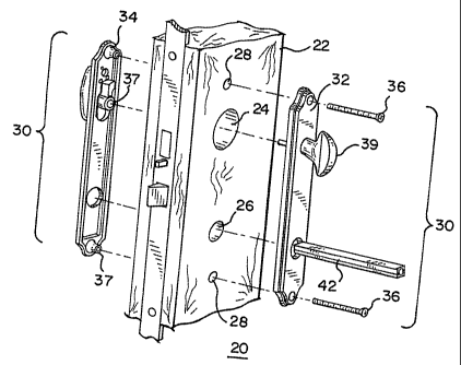
Referring now to FIG. 4, there is shown an exploded partial view of a door
assembly 20.
The door assembly 20 includes a door member 22 pivotally supported in a door
frame (not


CA 02440566 2004-03-11

4
shown). The door member 22 can be constructed from wood, metal or virtually
any material
without departing from the scope of the present invention. The door member 22
includes an
upper bore 24, a lower bore opening 26, and one or more fastening bores 28,
adapted for
receiving a door handle assembly 30.
The handle assembly 30 includes an interior escutcheon 32, an exterior
escutcheon 34, a
fastening member 36, a door handle or lever 38, a locking mechanism 39, a
spindle 42, and a set
screw or fastener 44. The interior escutcheon 32 engages one side of the door
member 22 and
exterior escutcheon 34 engages the other side of the door member 22. The
exterior escutcheon
34 includes one or more hub members 37 adapted for insertion into bore 28.
Similarly, the
interior escutcheon 32 can also include one or more hub members (not shown)
adapted for
insertion into bore 28.
Fastening members 36 are inserted into the bores 28, to fasten the exterior
and interior
escutcheons 34, 32 to the door member 22. The loclcing mechanism 39 is
inserted into the
upper bore 24 of the door member 22 and cooperatively engages the exterior
escutcheon 34.
The door handle 38 includes an opening 40, adapted to receive the spindle 42.
The handle 38
further includes a second opening 41 adapted to receive the set screw 44 or a
like fastening
member. As shown in FIG. 10, the set screw 44 has a generally cylindrical
shape, including a
tapered tip portion 46.

The spindle 42 is adapted for insertion into the lower opening 26 of the door
member 22.
2o The spindle 42 operatively engages the door handle 38. As shown in FIG. 10,
the spindle 42
generally comprises a first spindle member 48 and a second spindle member 50.
As explained
in greater detail below, the spindle members 48, 50 can be configured into a
specific
confronting relation to defme a predetermined outer dimension corresponding to
the door
handle opening 40. The spindle members 48, 50 are generally identical. FIGS. 6-
9 illustrate
one of the spindle members 48. Accordingly, the first spindle member 48 will
be described in
detail with the understanding that the description is applicable to the second
spindle member 50.
FIG. 6 shows the spindle member 48. The spindle member 48 has a generally
elongated
rod-shaped configuration having a first end 52 and a second end 54. The
spindle member 48
generally includes a base 56, a first leg 58 and a second leg 60. The base 56
has a generally
planar configuration. However, it is contemplated that the base 56 can have
virtually any shape
without departing from the scope of the present invention.


CA 02440566 2003-09-10

The first leg 58 projects generally perpendicularly outwardly from the base
56. The
first leg 58 extends between the first end 52 and second end 54 of the base
56. Preferably, the
first leg 58 has a length approximately equal to the length of base 56. The
second leg 60
projects generally perpendicularly outwardly from the base 56. The second leg
60 extends
5 between the first end 52 and second end 54 of the base 56. Preferably, the
second leg 60 has a
length approximately equal to the length of the base 56. The first leg 58 and
second leg 60 have
different heights. Preferably, the height of the first leg 58 is greater than
the height of the
second leg 60 such that the second leg 60 is recessed relative to the first
leg 58.
The first leg 58 includes a first pillar 62. In the present embodiment, the
first pillar 62 is
positioned proximate to a central portion of the first leg 58. Preferably, the
first pillar 62 has a
width approximately equal to half the width of the base 56. The second leg 60
includes a
second pillar 64. The second pillar 64 is positioned proximate to a generally
central portiori of
the second leg 60. Preferably, the second pillar 64 has a width equal to
approximately half the
width of the base 56. In the present embodiment, the first pillar 62 has a
height greater than the
second pillar 64 height such that the second pillar 64 is recessed relative to
the first pillar 62.
Preferably, the second pillar 64 and first pillar 62 engage each other
proximate to the mid-width
of the spindle member 42, forming a step 66.
A generally semi-circular cavity 68, 70 is formed proximate to the respective
first and
second ends 52, 54 of the spindle member 48. The cavity 68, 70 extends
generally from the
respective first and second ends 52, 54 of the spindle to the respective
pillars 62, 64. As
shown, the semi-circular cavity 68 forms a first tapered portion 72 in the
first leg 58, a second
tapered portion 74 in the second leg 60, and a generally thin wall section 76
in the base 56. The
thin wall section 76 is generally thinner in width than the peripheral corner
portions 78, 80 of
the base 56. Similarly, proximate to the second end 54, the semi-circular
cavity 70 forms a first
tapered portion 72 in the first leg, a second tapered portion 74 in the second
leg, and a generally
thin wall section in the base 56.

As explained in greater detail below, each spindle member 48, 50 is bowed at a
central
portion thereof. When the spindle members 48, 50 are properly positioned to
form the spindle
42, the bowed portions cooperate with the lower bore opening 26 of the door
member 22 to
provide an enhanced fit.


CA 02440566 2004-03-11

6
Referring now to FIG. 10, there is shown a view of the spindle members 48,50
in a
confronting position to form the spindle 42. In this arrangement, the bases 56
of the respective
spindle xnembers 48,50 are in a generally spaced relationship. The first leg
58a of the first .
member 48 confronts the second leg 60b of the second member 50, and the second
leg 60a of
the first member 48 confronts the first leg 58b of the second member 50. In
this manner, the
outer portions of the first leg 58 and second leg 60, in combination, define
the outer walls 82,84
of the spindle 42. As illustrated, the outer walls 82,84 are in a generally
spaced relationship.
Seams 90, 92 are formed between the cooperating first and second legs in the
respective outer
walls 82 and 84. The seam 92 is adapted to receive the set screw 44.
The first pillar 62 of the first member 48 confronts the second pillar 64 of
the second
member 50 and the second pillar 64 of the first member 48 confronts the first
pillar 62 of the
second member 50, forming a bow 86 at a central portion of the spindle 42.
Further, the first tapered portion 74 of the first leg 58 confronts the second
tapered
portion 76 of the second leg 60. The second tapered portion 76 of the second
leg 60 confronts
the first tapered portion 74 of the first leg 58. The semi-circular cavity 68
formed in the first
spindle member 48 and the semi-circular cavity 70 formed in the second spindle
member 50
define a circular cavity 88 formed in the end of the spindle. In a confronting
position, the bases
and walls form the spindle. As such, the spindle 42 has a peripheral
configuration having a
predetermined outer dimension. This outer dimension will correspond to the
opening 40 in the
door handle 38.

In the door handle assembly 30, the first end 52 of the spindle 42 is inserted
into the
opening 26. The second end 54 of the spindle 42 received by the opening 40 in
the door handle
38. As such, the bow 86 engages the opening 26, creating a secure interference
fit therewith.
The set screw 44 is inserted into the opening 41 in the handle 3 8. The set
screw 44 engages one

of the thinned bases 56 or sidewalls 82, 84 of the spindle 42 connecting the
handle 38 to the
spindle 42. I3referably, the spindle 42 is orientated in the door handle 38
such that the set screw
44 engages one of the seams 90 or 92 formed between the side walls 82, 84,
providing a secure
connection with the spindle 42.
The benefits of the present spindle assembly 42 are apparent. The spindle 42
includes a
plurality of thin walls, which enables embedded connection by the set screw 44
regardless of the
orientation of the spindle 42 in the handle 38. In the event that the spindle
42 is improperly


CA 02440566 2004-03-11

7
positioned in the handle opening, the first leg 58 of the first and second
spindle member 48, 50
extends outwardly, preventing the spindle 42 from being improperly installed
in the handle 38
and door member 22. Further, in the event that the first and second spindle
members 48, 50 are
improperly installed such that the base 56 of one member confronts the pillars
62, 64 of the
other member, the extending first legs and first pillars prevent the first and
second member from
mounting to form the spindle 42. In these improper configurations, the outer
dimensions of the
spindle members 48, 50 will exceed the predetermined outer dimension of a
properly configured
spindle 42. In such case, the spindle 42 in an improper configuration will not
fit into the
opening 40 of the door handle 38. In a proper confronting position, the first
and second pillars
62, 64 of the first and second members 48,50 cooperatively form a bow 86. When
the spindle
42 is inserted in the opening 26 of the door member 22, the bow 86 provides a
secure
interference fit with the opening 26.
It will be understood that the invention inay be embodied in other specific
forms without
departing from the spirit or central characteristics thereof. The present
embodiments, therefore,
are to be considered in all respects as illustrative and not restrictive, and
the invention is not to
be limited to the details given herein.

Representative Drawing
A single figure which represents the drawing illustrating the invention.
Administrative Status

For a clearer understanding of the status of the application/patent presented on this page, the site Disclaimer , as well as the definitions for Patent , Administrative Status , Maintenance Fee  and Payment History  should be consulted.

Administrative Status

Title Date
Forecasted Issue Date 2008-04-29
(22) Filed 2003-09-10
Examination Requested 2003-09-30
(41) Open to Public Inspection 2004-03-11
(45) Issued 2008-04-29
Deemed Expired 2013-09-10

Abandonment History

There is no abandonment history.

Payment History

Fee Type Anniversary Year Due Date Amount Paid Paid Date
Application Fee $300.00 2003-09-10
Request for Examination $400.00 2003-09-30
Registration of a document - section 124 $100.00 2004-09-10
Maintenance Fee - Application - New Act 2 2005-09-12 $100.00 2005-08-29
Maintenance Fee - Application - New Act 3 2006-09-11 $100.00 2006-08-23
Maintenance Fee - Application - New Act 4 2007-09-10 $100.00 2007-08-22
Final Fee $300.00 2008-02-13
Maintenance Fee - Patent - New Act 5 2008-09-10 $200.00 2008-08-18
Maintenance Fee - Patent - New Act 6 2009-09-10 $200.00 2009-08-19
Maintenance Fee - Patent - New Act 7 2010-09-10 $200.00 2010-08-17
Maintenance Fee - Patent - New Act 8 2011-09-12 $200.00 2011-08-17
Owners on Record

Note: Records showing the ownership history in alphabetical order.

Current Owners on Record
NEWELL OPERATING COMPANY
Past Owners on Record
REEVES, STANLEY R.
WALLS, CHRISTOPHER G.
Past Owners that do not appear in the "Owners on Record" listing will appear in other documentation within the application.
Documents

To view selected files, please enter reCAPTCHA code :


To view images, click a link in the Document Description column. To download the documents, select one or more checkboxes in the first column and then click the "Download Selected in PDF format (Zip Archive)" or the "Download Selected as Single PDF" button.

List of published and non-published patent-specific documents on the CPD .

If you have any difficulty accessing content, you can call the Client Service Centre at 1-866-997-1936 or send them an e-mail at CIPO Client Service Centre.


Document
Description 
Date
(yyyy-mm-dd) 
Number of pages   Size of Image (KB) 
Abstract 2003-09-10 1 14
Description 2003-09-10 7 419
Claims 2003-09-10 5 218
Cover Page 2004-02-13 1 42
Drawings 2003-09-10 3 81
Representative Drawing 2003-11-03 1 17
Description 2004-03-11 7 419
Claims 2006-10-19 7 309
Representative Drawing 2008-04-11 1 20
Cover Page 2008-04-11 2 48
Correspondence 2003-10-06 1 24
Assignment 2003-09-10 2 92
Prosecution-Amendment 2003-09-30 1 33
Prosecution-Amendment 2004-03-11 5 239
Assignment 2004-09-10 5 194
Fees 2005-08-29 1 27
Prosecution-Amendment 2006-04-19 2 83
Fees 2006-08-23 1 35
Prosecution-Amendment 2006-10-19 11 438
Fees 2007-08-22 1 26
Prosecution-Amendment 2007-12-11 2 42
Correspondence 2008-02-13 2 40
Correspondence 2008-09-23 5 412
Correspondence 2008-10-20 1 13
Correspondence 2008-10-21 1 21