Note: Descriptions are shown in the official language in which they were submitted.
CA 02441900 2003-09-22
WO 02/082152 PCT/GB02/01374
-1-
OPTICAL FIBRE ORGA1VISER
The present invention relates to an optical fibre organiser. More in
particular, the
present invention relates to an optical fibre organiser comprising trays in
which optical
fibres can be guided, spliced and/or stored.
Organisers of this kind are well known. They are used in, for example, optical
fibre splice closures and optical fibre management cabinets. An individual
tray may be
dedicated to a single task, such as overlength storage, or may combine several
tasks, such
as splicing and overlength storage.
There is an increasing need for optical fibre organisers having a compact
design yet
providing optical fibre management with a high degree of organisation for
relatively large
numbers of optical fibres.
International Patent Application WO 00/58769 (Tyco Electronics Raychem) [B365]
discloses a folding cassette, the upper and lower parts of which constitute
optical fibre
trays. Such an arrangement can be compact while providing a unit that can be
easily
handled. The location of the ports providing access to this known cassette is
determined
by its use in an optical fibre system.
It is an object of the present invention to provide an optical fibre organiser
which
has an even greater fibre handling capacity without requiring a large number
of parts.
It is another object of the present invention to provide an optical fibre
organiser
which offers a greater flexibility with respect to the position and number of
access ports.
It is a further object of the present invention to provide an optical fibre
organiser
which is versatile yet economical.
In accordance with the present invention, these and other objects are met by
an
organiser for optical fibres, comprising a base tray and a main tray, said
trays being
CA 02441900 2003-09-22
WO 02/082152 PCT/GB02/01374
-2-
hingedly connected so as to provide an opened position in which access to the
trays is
facilitated and a closed position in which the base tray is at least partially
covered by the
main txay, the base tray comprising at least one port for passing optical
fibres into and out
of the organiser and guide means for guiding optical fibres within the tray,
the main tray
having a first side facing away from the base tray and a second side facing
towards the
base tray, both the first side and the second side having guide means for
guiding optical
fibres.
By providing a base tray in which the at least one access port of the
organiser is
located, the number and/or position of the access port or ports can be
modified by only
changing the design of the base tray. It is therefore possible to form an
organiser out of a
"universal" main tray and base tray specifically selected or designed for the
particular
application. In this way, a large degree of flexibility is obtained.
By providing a main tray both sides of which have guide means for guiding
optical
fibres a very large fibre handling capacity is obtained. In such a double-
sided tray one
side may for example be used for fibre overlength storage, while the other
side may be
used for splicing. Of course it is also possible to use both sides for
overlength storage
and/or splicing. However, by dedicating each side to a single task a high
degree of
organisation is obtained.
The above-mentioned guide means for guiding optical fibres may be constituted
by
grooves and/or upstanding ridges which are either straight or have a radius of
curvature
which is equal to or larger than the minimum bend radius of the optical
fibres.
Although the main tray may be provided with ports which provide access to the
organiser as a whole it is preferred that such ports are only located on the
base tray. It is
then possible for the base tray to merely receive and guide incoming fibres
and pass and
guide outgoing fibres, while the actual fibre management tasks of e.g.
splicing and storing
may be assigned to the main tray. The base tray may comprise means for
facilitating the
receiving of incoming fibres, such as cable termination means (e.g. cable
clamps, strength
member clamps, break-out devices).
CA 02441900 2003-09-22
WO 02/082152 PCT/GB02/01374
-3-
As stated above, fibres received in the base tray are passed to the main tray
and
eventually back to the base tray. To facilitate fibre management and to
protect the fibres,
the organiser is preferably provided with at least one fibre guide for guiding
optical fibres
from the base tray towards the main tray, and preferably vice versa.
Advantageously, the
at least one fibre guide is located on the base tray, thus freeing the surface
of the main
tray for the core tasks of splicing, storing etc..
In a preferred embodiment the at least one fibre guide is designed so as to
guide
fibres away from a main surface of the base tray to a main surface of the main
tray. As
the main surface of the main tray is spaced apart from the main surface of the
base tray so
as to provide space for the fibres and for components of the organiser, this
guiding away
implies a three-dimensional design of the fibre guides.
Advantageously, at least two fibre guides extend to the first and the second
side of
the main tray respectively. That is, the fibre guides may extend different
distances from a
main surface of the base tray. It will be understood that the appropriate
distances are
determined by the relative positions of the trays when the organiser is in its
closed
position. However, the fibre guides preferably end near the hinging means
connecting the
trays so as to minimise the influence of the hinging on the fibres.
Preferably, at least one said fibre guide extends from within the base tray.
It will
be understood that a tray is normally provided with upstanding peripheral
walls and that
the at least one fibre guide extends from within the area defined by those
walls. It is,
however, also possible that at least one said fibre guide extends :From
outside the base tray.
In such an embodiment the entrance to this "external" fibre guide constitutes
an additional
port to the organiser.
In a preferred embodiment the main tray is provided with a through port
providing
a passage between the first and the second side. In this way fibres can easily
be guided
from e.g. the storage side of the main tray to e.g. the splicing side without
having to lead
the fibres via the base tray.
CA 02441900 2003-09-22
WO 02/082152 PCT/GB02/01374
-4-
Preferably, the through port is open to one side of the tray so as to provide
side-
entry. This allows uncut fibres to be passed through the through port.
To assist the fibres being guided between the trays, especially when the
organiser
is hinged open, it is preferred that the main tray is provided with at least
one fibre guiding
tongue extending substantially in the plane of the main tray beyond the
hinging axis.
Advantageously, the guiding tongue is located near one end of at least one
fibre guide.
In a preferred embodiment one surface of the main tray is provided with
retaining
means for retaining optical fibre splices, said surface preferably being the
second surface.
In that embodiment, the first side is preferably used for overlength storage.
To provide
storage facilities at least one surface of the main tray is preferably
provided with an island
around which optical fibres can be wound, the island having a radius of
curvature at least
equal to the minimum bend radius of the optical fibre. Said island may be
constituted by
upstanding walls or by a raised section of the tray. To allow fibres to be
looped, the
island may be intersected by an X-shaped arrangement of grooves.
To be able to easily take the organiser apart so as to exchange e.g. the base
tray,
the organiser of the present invention is preferably provided with releasable
hinging
means.
An organiser of this kind may have gaps in its surfaces. Some of those gaps
may
serve a fibre management purpose, such as the through port between the sides
of the main
tray. Other gaps may be present for technical reasons, e.g. to facilitate
moulding the
trays. In both instances, an interruption of a fibre guiding surface may form
an obstacle
when feeding fibres through the organiser, the fibres possible continuing on
the wrong
side of the surface beyond the gap. According to a further aspect of the
present invention
at least one gap in a tray surface is preceded, in the feeding direction of
the optical fibres,
by a ramp. Such a ramp may be formed by a hump or protrusion located near the
edge of
the gap. The length, the shape and the height of the ramp are chosen so as not
to
compromise the minimum bend radius of the optical fibres.
CA 02441900 2003-09-22
WO 02/082152 PCT/GB02/01374
-5-
The present invention further provides a kit-of parts for forming an organiser
as
defined above.
The present invention will be described in more detail below with reference to
exemplary embodiments illustrated in the accompanied drawings, in which:
Figure 1 shows, in perspective, a first embodiment of the organiser according
to
the present invention in an open position;
Figure 2 shows, in perspective, the organiser of Fig. 1 in a closed position;
Figure 3 shows, in perspective, a second embodiment of the organiser according
to
the present invention in an open position;
Figure 4 shows, in perspective, the organiser of Fig. 3 in a closed position;
and
Figure 5 shows, in side view, part of the organiser of Fig. 1.
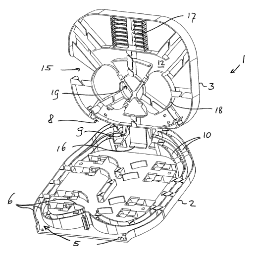
The organiser 1 shown merely by way of non-limiting example in Fig. 1
comprises
a base tray 2 and a main tray 3. Both trays are provided with upstanding walls
6 for
optical fibres. The trays are hingedly connected by means of releasable hinges
9. The
organiser 1 is provided with access ports 5 constituted by openings in the
side walls of the
base tray 2. Further access ports may be provided on the opposite (lower) face
of the base
tray 2 (not shown).
Fibre guides 10 are provided to guide optical fibres from the base tray 2
towards
the main tray 3. As can be seen in Fig. 1, the fibres guides 10 are
constituted by
upstanding walls 6 and sections of the surface of the base tray 2. As the
surface of the
main tray 3 is spaced apart from that of the base tray 2, also in the closed
position of the
organiser shown in Fig. 2, the fibre guides slope upwards, away from the
surface of the
base tray 2 so as to define a smooth trajectory for the optical fibres. A
tongue 16
protruding from the main tray 3 beyond the hinging axis (at 9) serves to
further guide the
fibres towards ports 8 of the main tray. It should be noted that the ports 8
are internal to
the organiser, in contrast to the access ports 5.
The (second) surface 12 of the main tray 3 is provided with optical fibre
splice
CA 02441900 2003-09-22
WO 02/082152 PCT/GB02/01374
-6-
holders 17 in which optical fibre splices can be accommodated, and an island
18 around
which overlength fibre can be wound. This enables the side 12 of the main tray
3 to be
used both for splicing and for overlength storage. The X-shaped grooves 19 in
the island
18 serve to accommodate a loop in the fibre. A through port 15, which is open
to one
edge of the main tray 3, serves to pass fibres from the (second) side 12 shown
in Fig. 1 to
the (first) shown in Fig. 2. The through port 15 shown allows side-entry of
optical fibres,
thus making it possible to accommodate uncut fibres.
The ports 5 shown in Fig. 1 substantially face in two opposite directions,
allowing
to receive fibres from and pass fibres into those directions. In the
alternative embodiment
shown in Fig. 3 eight forward facing ports 5 are provided along one side of
the base tray
2, while an additional port 5' is provided to the side of the base tray. The
regular ports 5
are provided with cable termination devices 13 which preferably are the cable
termination
devices disclosed in British patent application 0106231.4 (Tyco Electronics
Raychem).
Bend control means 7 are positioned behind these ports 5.
The additional port 5' leads directly to a fibre guide 10 and "by-passes" the
main
area of the base tray 2. This embodiment is particularly suitable for
receiving optical
fibre cables via the additional port 5' , leading them directly to the main
tray 3. In the
main tray 3 they are spliced to so-called drop cables which are then fed,
through the base
tray 2 towaxds the regular ports 5. The upper or first surface 11 of the base
tray 3, shown
in Fig. 4, serves for overlength storage. Due to the X-shaped pattern 19 it is
possible to
accommodate loops of uncut fibre cables.
The base tray 2 of Fig. 1 is shown in side view and partial cross-section in
Fig. 5.
As clearly shown in Fig. 5, the fibres guides 10 rise up from the base tray 2
and reach
different levels corresponding to the plain of the first side 11 and the
second side 12 of the
main tray 3 respectively.
Gaps 21 in the base tray 2 are provided with small ramps 20 which serve to
direct
a fibre fed through the guides. These ramps 20 prevent fibres 22 from entering
the gap
and diverging from their intended course. This clearly facilitates the feeding
of fibres
CA 02441900 2003-09-22
WO 02/082152 PCT/GB02/01374
_ '7 _
through the organiser. As shown in Fig. 5, the ramps 20 may be located on one
edge of a
gap only to facilitate feeding fibres in one particular direction (indicated
by an arrow). It
is, however, also possible to provide ramps on both sides of a gap.
The presence of the ramps 20 is of course not limited to the fibre guides 10
or to
the base tray 2 but may also be used in the main tray 3, in particular near
the through port
15.
It will therefore be r nderstood by those skilled in the art that the present
invention is
not limited to the embodiments shown and that many additions and modifications
are
possible without departing from the scope of the present invention as defined
in the
appending claims.