Note: Descriptions are shown in the official language in which they were submitted.
CA 02446731 2003-11-07
WO 02/098338 PCT/US02/13160
VACUUM FORMED FILM TOPSHEETS HAVING A SILKY TACTILE
IMPRESSION
CROSS REFERENCE TO EARLIER APPLICATIONS
This patent application claims priority from United States Patent Application
No. 09/876,440, filed on June 6, 2001 entitled "VACUUM FORMED FILM
TOPSHEETS HAVING A SILKY TACTILE nVIPRESSION".
FIELD OF THE INVENTION
The present invention relates to disposable absorbent products. More
particularly,
the present invention relates to an apertured, vacuum formed film having
properties that
give the film a silky tactile impression or silky feel when the film is
stroked by a user.
BACKGROUND OF THE INVENTION
Advances in film forming technology have yielded improvements in disposable
absorbent products such as disposable diapers, feminine hygiene products and
the like.
"Film" is a common term for thermoplastic polymer webs made from any variety
of
processes. The most common method of producing films is with an extrusion
process.
Cast extrusion and blown extrusion are commonly known methods in the film
producing industry. In a blown extrusion process, a circular die extrudes an
inflated
bubble of film that is cooled by cool air streams blown onto the bubble's
perimeter by an
air ring. The bubble is then flattened in a nip and subsequently slit into
flat sheets that can
then be reheat embossed or otherwise manipulated. Blown film can be used to
create a
roll of precursor film that may be fed into a reheat vacuum formed film (VFF)
process.
This method is taught by United States patent 4,151,240 to Lucas.
Additionally, it is also
known to use a precursor roll of cast film.
In a cast extrusion process, a flat web is extruded from a slot die. The flat
web is
subsequently cooled and set by a variety of chilling roller means. As an
example, United
States patent 4,456,570 to Thomas teaches a cast extrusion in a direct melt
vacuum
formed film (VFF) process. In a vacuum formed film process, a pressure
differential is
applied across a forming screen. In the case of a direct melt VFF process, a
molten web
1
CA 02446731 2003-11-07
WO 02/098338 PCT/US02/13160
is extruded onto a forming area of a forming screen. An example of a direct
melt VFF
process is taught by United States patent 4,456,570 to Thomas. United States
patent
4,151,240 to Lucas teaches reheating and partially melting a web while the web
is over
the forming area of the forming screen. A melted polymer is desirable to form
three-
s dimensional apertures since a melted polymer is more easily sucked into the
apertures in
a forming screen. Both USPN 4,456,570 to Thomas and USPN 4,151,240 to Lucas
teach
primarily using vacuum as a main source of pressure differential energy that
is used for
the work energy that changes a two dimensional web into a three dimensional
cell and
causes an aperture to open in a film web. During the formation of a VFF, the
polymer
of the film typically undergoes a phase change from molten state in a flat
form to a
crystalline state in the new three dimensional form.
In some cases, it is desirable to form textures on the lands of the VFF. To
form
textures on the lands of the vacuum formed film, lands are provided on the
forming screen
with textures provided thereon. The textures on the forming screen are then
incorporated
into the direct melt VFF film. Due to vacuum pressure, textures form on the
lands of the
subsequently formed VFF. As discussed above, the vacuum pressure differential
also
causes 3-D cells with apertures to be formed in the film.
The textures imparted on the VFF may be formed in a pattern. Examples of
embossing patterns include straight lines, pyramids, diamonds, squares, and
random matte.
Further, more exotic patterns may be used including, exotic squiggly lines,
spiral pattens,
microscopic flower petals, and other ornamental designs.
A micropattern can also be incorporated into a precursor film by a reheat VFF
process, via either cast embossing or blown embossing processes that are well
known in
the industry and that are discussed above. In a reheat process, external heat
is applied to
partially melt and form three dimensional cells with apertures. Portions of
the precursor
film rest on the lands ofthe screen, which partially protects these portions
ofthe precursor
film from the heat. Therefore, only the portion of the film suspended over an
opening of
a cell in the forming screen is fully unprotected from exposure to heat. Thus,
the
suspended portion becomes melted and forms a three dimensional cell with an
aperture.
When a film layer is applied to a forming screen, the film layer typically has
about
25 to 80 times less mass than a metallic screen mass beneath the film layer.
Because of
2
CA 02446731 2003-11-07
WO 02/098338 PCT/US02/13160
the mass ratio of the film layer to the screen, the screen acts as a "heat
sink" in the land
area where the precursor film is in intimate contact with the lands of the
forming screen.
The heat passes through the thin film and is absorbed by the screen such that
no, or
negligible, thermal distortion occurs on the land regions. As a result, any
texturizing
S pattern embossed into the precursor film is maintained in the finished VFF.
Films produced by the methods above may be constructed of various materials
having a selected mesh count, embossed thickness, a selected aperture pattern,
a selected
width of the lands or spaces between the apertures, and a selected pattern may
be formed
on the lands. The "mesh count" is the number of cells aligned in 2.54 cm (one
inch) of
distance. Other variations may also be possible. Each configuration will
exhibit distinct
properties with respect to performance.
When measuring a VFF for percent open area, it is common to use any of the
many computerized video devices that are available. The video camera, via
magnification
and contrast, can discern the openings from the lands and digitize the data to
calculate the
percent open area.
Unlike nonwoven material (NW), which exhibits capillary action for wicking
fluids, formed films are made from polymer webs that do not transmit fluid
unless the
formed film is "formed" into a three-dimensional apertured sheet. Formed films
may be
tested for rewet. A lower rewet value is more desirable. Generally, preferred
products
have had a rewet value of less than one gram; i.e. a "fractional gram". It has
been found
that products with a gram or more of rewet are typically viewed by consumers
as being
wet or damp in use.
Fluid acquisition rate is also critical to a functional topsheet. If the fluid
acquisition rate is too slow, then a product using the topsheet may leak. The
fluid
acquisition rate is affected by several factors. The surface energy of the
vacuum formed
film is critical for fluid acquisition rate. Additionally, the fluid
acquisition rate is directly
correlated to open area. Additionally, the "loft", or the required special
distance between
a fluid containing absorbent core and the skin of the user, must also have a
certain
measure to prevent a wetness factor of one gram or greater as exhibited by
rewet values.
Simply stated, if there are relatively large openings, as indicated by high %
open area, and
comparatively little separation space, as indicated by low loft, then fluid
can overcome
3
CA 02446731 2003-11-07
WO 02/098338 PCT/US02/13160
the short expanse of space through the center of the large opening, which
results in
reverse flow, or "rewet".
Table 1, below, is derived from selected feminine napkin products from around
the
world that use a formed film coversheet. From the data in Table l, the ratio
correlation
can be seen. From such data, the apparent line of separation of the loft to %
open area
ratio (L/OA Ratio) between a "dry" coversheet and "damp" coversheet would
logically
be about a L/OA Ratio of > 10.
TABLE 1
Product Loft, Open Area,L/OA RatioRewet, grams
,um %
Always 550 32.0 17.0 0.05
Equate 455 28.5 16.0 0.15
Siernpre Libre450 20.0 22.0 0.12
'Itimus 370 20.0 18.5 0.10
CareFree (Euro)130 25.0 5.2 4.85
Magix 100 21.5 4.5 6.15
Centre Libre 190 25.0 7.6 1.90
The term "rewet" implies that all ofthe fluid passes through the topsheet and
then
only the fluid coming back to the surface to "rewet" it is measured. However,
with the
many varieties ofmicro-embossing, crimping, and punching involved with these
materials,
often "wells" can be formed that trap fluid on the surface. The entrapped
fluid accounts
for about 15% ofvariation in the data. Also, as with any reliable test method,
the method
itself will have some variation of results, even within a given single
material. This is
offered to explain why the correlation is not exactly linear as, in theory, it
should be.
Hole diameter is determined by the narrowest width of an aperture
(specifically
for aperturing oval or elliptical shapes) that can be determined as a function
of mesh count
and land width. From mesh count and land width, one can derive an approximate
hole
diameter, or span of the "supports" for the polymer sheet to be apertured.
A hole diameter of a typically known 60 mesh forming screen is usually no more
than 200,um. Since a reasonable amount of metal must remain between holes in a
forming
screen (such that it will be robust enough to run in the VFF process), one can
calculate
4
CA 02446731 2003-11-07
WO 02/098338 PCT/US02/13160
hole diameter as follows. As explained above, "mesh" is the number of cells
aligned in
one inch of distance; hence, 2.54cm/60 = 425,um (1160 =.017 inch) center to
center. One
will need about 230,um of metal land area to have a robust screen, leaving the
nominal
200,um hole diameter for a 60 mesh pattern.
~ In addition to rewet performance and fluid acquisition performance during
use, it
has been found that the feel or tactile impression of a topsheet is important
to consumers.
Silk has been known for centuries to impart a unique and highly desirable
tactile
impression that has no other description than to say, "This feels silky". The
term "silky"
alone provides enough description for average global consumers to grasp its
meaning and
recognize whether or not a product feels "silky" or merely soft and clothlike.
In repeated
blind panel tests various fabrics such as felt, flannel, cotton diapers,
polyester/cotton
clothing fabric, wool, and silk were tested. The panels easily discern a silky
tactile
impression (STI) of silk cloth over the other cloth materials.
For many years, the feminine napkin market has been segmented into women who
prefer a nonwoven coversheet and women who prefer a film coversheet. The
market
segmentation is particularly found in westernized countries. Those who prefer
the
nonwoven type seem to prefer the clothlike tactile impression and the
perceived "comfort"
that they derive from it.
Users of the nonwoven type, however, sacrifice the dry cleanliness of the VFF
type. Nonwovens have capillarity due to having their many fibers in close
proximity to
the absorbent core. Capillarity is good for transmitting fluid through a
coversheet via the
capillary action of the nonwoven. Unfortunately, "wicking" by capillary action
can also
act in reverse. Therefore, nonwovens are not known for providing good rewet
values.
A good rewet value is indicative of dry cleanliness during use.
Those who prefer the film type seem to prefer the improved cleanliness and
anti-
rewet, particularly that of the VFFs. Many VFF coversheets have large openings
which
readily accept semi-coagulated matter found in menses. VFFs also provide the
afore-
mentioned prevention of the fluid rewetting to the top plane of the film. The
prevention
of rewet is derived from the superior loft of the VFF material. Hence, those
who prefer
the prior art film type forgo a bit of clothlike tactile impression derived
from the presence
of fibers of a nonwoven to achieve the cleanliness, which is especially true
of a VFF. A
5
CA 02446731 2003-11-07
WO 02/098338 PCT/US02/13160
film that delivers the perceived comfort of a nonwoven with the improved
cleanliness and
anti-rewet is desirable. Therefore, much effort has been made in attempts to
derive the
benefits of both types, some with market success; however, no VFF to date has
delivered
both the cleanliness and a silky tactile impression.
SUMMARY OF THE INVENTION
The present invention relates to a vacuum formed film that delivers desirable
rewet
properties and possesses a desirable silky tactile impression or silky feel to
a user. In one
embodiment, the vacuum formed film has a plurality of cells, wherein the cells
are ellipse
shaped, each having a major axis and minor axis. In another embodiment, the
cells are
boat shaped, wherein the ends on each end ofthe major axis axe rounded off. In
another
embodiment the cells may be oval shaped. Major axes of the cells are aligned
in the
stroking direction of the vacuum formed film. The cells define stroking
direction lands
and a transverse direction lands in areas between the cells. In one
embodiment, the
stroking direction lands are raised with respect to said transverse direction
lands. In yet
another embodiment, micro-ridges are formed on the lands for imparting a silky
feel to the
vacuum formed film. The various film aspects, above, each contribute to the
silky tactile
impression of the film. In still further embodiments, some or all of the
various aspects
described above may be combined to achieve a fizrther improved silky tactile
impression.
The loft to open area ratio of the vacuum formed film is preferably greater
than about 9
and preferably has a rewet of less than about 1 gram.
BRIEF DESCRIPTION OF THE DRAWINGS
Figure 1 is a perspective view of a feminine napkin utilizing a film ofthe
invention.
Figure 1 A is an plan view of a section of forming screen having an oriented
ellipse
pattern.
Figure 1B is a cross-sectional view ofthe forming screen ofFigure 1A taken
along
line 1B-1B ofFigure 1A.
Figure 1 C is a cross-sectional view of the forming screen of Figure 1 A taken
along
line 1 C-1 C of Figure 1 A.
6
CA 02446731 2003-11-07
WO 02/098338 PCT/US02/13160
Figure ZA is a plan view of a second embodiment of a section of forming screen
having an oriented ellipse pattern.
Figure 2B is a cross-sectional view of the forming screen of figure 2A taken
along
line 2B-2B of Figure 2A.
Figure 2C is a cross-sectional view of the forming screen ofFigure 2A taken
along
line 2C-2C of Figure 2A.
Figure 3 is a plan view of a section of film having an oriented ellipse
pattern
wherein the film has a single plane on all lands.
Figure 4 is a plan view of a section of film having an oriented ellipse
pattern
wherein the film has a highest plane on stroking direction lands.
Figure SA is a plan view of a male side of a section of film having boat
shaped
cells.
Figure SB is a plan view of a female side of a section of film having boat
shaped
cells.
1 S Figure 6A is a plan view of a female side of a formed film material having
micro-
ridges on the lands of the film.
Figure 6B is a plan view of a male side of a formed film material having micro-
ridges on the lands of the film.
Figure 7 is a cross-sectional view of the formed film material of Figures 6A
and
6B taken along line 7-7 of Figure 6B.
DETAILED DESCRIPTION OF THE INVENTION
Both direct melt and reheat processes are, in this invention, considered to be
equivalent methods under the term vacuum formed films (VFF). Since both melt,
form,
and recrystallize in a three dimensional shape, each of the processes may be
used to form
films wherein the Loft of the cells are robust. Polymer webs have a property
known as
"memory" wherein a polymer web will tend to revert to its original shape.
Therefore, if
a polymer web is formed as a flat web and then forced into a three dimensional
shape
without undergoing melting and recrystallizing, the polymer web will try to
revert again
to its original flat shape when any stresses are subsequently applied.
Robustness in the
3 0 third dimension is critical for obtaining and then maintaining "loft",
which prevents rewet.
7
CA 02446731 2003-11-07
WO 02/098338 PCT/US02/13160
Two important variables are commonly discussed when describing a VFF, loft and
AO. "Loft" is defined as the top to bottom thickness of the vacuum formed
film, which
is typically the required spacial distance between a fluid containing
absorbent core and the
skin of the user or the thickness of the vacuum formed film. Loft is typically
measured by
the same means used to measure "Embossed Thickness" in the polymer film
industry.
Embossment is merely imparting a third dimension to the film, typically one
with defined
pattern and shape. Commonly used devices for this measurement are called "Low
Load
Micrometers". A wide area of displacement with a low compression load is
utilized to
insure one is measuring the full depth of pattern and one is not compressing
the pattern
to render a false reading. A TMI~ Model 49-70 manufactured by Testing
Machines, Inc.
of Amityville, NY was used for the loft measurements herein. This relationship
of
properties ties directly to rewet performance and is a simple calculation of
dividing loft,
' as measured in micrometers (,um), by the percent open area (17.3%,
for.example). As an
example, a packing of 60 mesh round holes on a square pattern packing array,
has a .
percent open area (OA%) that can be calculated as follows:
SI Units:
~ OA%={((mesh x mesh [due to square array]) x area of each hole, in
cm)=(2.54cm)2} X 100
~ A 60 mesh hole is 200~m in diameter, 200~m / 10,000,um/cm = 0.02 cm diameter
~ D/2=Radius; hence, Radius (R) = 0.02cm/2 = 0.01 cm
~ Area = ~RZ= 3.14159 x (O.Olcm)2 = 0.00031cm2
~ mesh x mesh = 60 X 60 = 3600
~ {( 3600 x (0.00031cm2 ))= (2.54cm)2} x 100 = 17.3% Open Area
US Units:
~ OA%={((mesh x mesh [due to square array]) x area of each hole, in inches) =
1 inchz} X 100
~ A 60 mesh hole is 200um in diameter, 200~m /( 25,400,um/inch) = 0.00787 inch
diameter
~ Dl2=Radius; hence, Radius (R) = 0.00787inch/2 = 0.0039 inch
~ Area = ~RZ= 3.14159 x (0.0039 inch)Z= 4.8x10⁻⁵ inch2
~ mesh x mesh = 60 X 60 = 3600
~ {( 3600 x (4.8 x 10-Sinch2)) = 1 inch2} x 100 = 17.3% Open Area
8
CA 02446731 2003-11-07
WO 02/098338 PCT/US02/13160
For this invention it has been surprisingly discovered that by a combination
of
pattern, plane and texture, a VFF providing adequate "loft to % open area
ratio" for
achieving good rewet values can also attain a desirable silky tactile
impression (STI).
It has been discovered that STI may be improved by selecting a specific range
of
mesh count from about 28 to 60, preferably 40. If fewer cells exist, it has
been found that
users can begin to sense the individuality of cells, which can detract from
the STI effect.
The STI may be further improved with an oval, boat shaped or elliptical cell
having a
major axis to minor axis ratio of at least about 1.05:1.0 to as much as about
6.5: l, more
preferably ranging from about 1.5:1 to 4:1. The STI may be still further
improved by
aligning all the major axes substantially in the same direction. For purposes
of this
application, the stroking direction (SD) shall be defined as the direction
along a length of
an end product, e.g., feminine napkin or the like. Figure 1 shows sample
product 5.
' Arrow 7 shows the stroking direction. The stroking direction is typically
the direction
that a consumer strokes the material when assessing the film. It is desirable
to align the
1 S stroking direction in a direction most likely to rub back and forth
against a user during
use, i.e. typically in a front to back orientation. By implementing the above
steps, a
discernable panel test result may be achieved for STI as compared to other VFF
topsheets
and synthetic silk-like nonwoven materials previously known in the art.
Further, it is commonly understood by those skilled in the art that the
"machine
direction" (MD) is the processing direction when manufacturing formed films,
and with
rare exception, when converting the formed film as a topsheet on an absorptive
device.
The MD is the direction where the web of the materials) moves continuously
down a
machine. As it relates to the forming screens, the MD is the circumference of
the screen
and the "Transverse Direction" (TD) is from the end to end length of the
screen. As is
commonly understood, the forming screen rotates around a stationary seal.
Therefore,
the circumferential direction is the direction of continuous motion feeding
film down the
machine in the "Machine Direction". While not typical or commonly used,
alterations
from this norm will be understood by a man of the art; therefore, these are
not intended
as limiting to this invention.
On most conversion lines that take the VFF and place it as a topsheet, diapers
or
pads or bandages or whatever absorptive device is being manufactured will
align the MD
9
CA 02446731 2003-11-07
WO 02/098338 PCT/US02/13160
of topsheet down the length, or greatest dimension, of the product. Especially
for
feminine napkins, the difference of length to width is significant. In many
tests when
napkins are handed to women, they will typically stroke the topsheet down the
length of
the product as shown in Figure 1. Consequently, it is generally the case that
the stroking
direction is synonymous with the machine direction, although this need not be
the case to
fall within the scope of the applicant's invention. For a consumer, the first
perceptive
triggers are gained by stroking the topsheet in the fashion described above
when a
consumer desires to know how the product will feel in use.
The length is also aligned with the anatomy of common disposable articles.
Since
disposable articles are typically held in the groin between the legs there is
little chance of
side to side or TD motion. If the product shifts during the natural motions of
the user, the
shift will almost always occur in the MD creating a "stroking" action of the
topsheet
against the skin. As explained above, and from all these correlated factors it
can be seen
that the term "MD" and "SD" are typically synonymous. The STI effect is gained
by a
stroking motion. Hence, the reference to the "Stroking Direction" (SD).
For purposes of this application, the term "oval" shall relate to a rounded
shape
with a major and minor axis whose lines along the major axis direction are
essentially
curved. The term "ellipse" shall differ in that the lines along the major axis
direction are
essentially straight. Hereafter, the ratio of major axes to minor axes shall
be referred to
as the SD:TD ratio wherein SD is the stroking direction's alignment ofthe
major axes, and
TD is the transverse direction of the minor axes. Although not essential for
achieving the
STI effect, it has been found that the STI effect is enhanced if the centers
of major axes
are commonly aligned with each other.
Again, while not essential for attaining STI effect, the STI effect may be
further
enhanced if the lands in the SD are on a slightly higher plane than the lands
in the TD.
Also, the STI can be triggered with this step alone. If SD lands are in a
slightly higher
plane, higher STI rankings are received when compared to single plane material
of the
same configuration. It has been found that as little as l5,um variance shows a
slight
distinction, although a 35,um variance is preferred. If a film has greater
than a 145,um
variance between the SD lands and the TD lands, then problems can occur with
the
strength of the forming screen, especially in the case of finer mesh counts.
Winding
CA 02446731 2003-11-07
WO 02/098338 PCT/US02/13160
issues, such as roll blocking due to nesting, may be introduced, as well.
Since the SD
lands are raised, it is less critical to have rounded cell geometries. Many
polygonal shapes
will also function, such as squares, hexagons, pentagons or other shapes.
The variance in the height of the planes of the SD land plane and the TD land
plane can be achieved by machining a forming screen with cutting tools,
grinding, etching,
cutting with energy beams, or affixing wires to alter the external profile of
the screen to
form bi-planar lands. Additionally, other means may be used for varying the
height of SD
lands.
Also non-essential, but preferred, for increasing the STI effect is the
addition of
various texturizations to the lands. More preferred is the addition of micro-
ridges (MR)
of a specific height and spacing. Films having micro-ridges received
surprisingly high
panel test recognition of STI when the micro-ridges were applied to films
having mesh
counts of 28 or greater and especially to films having a 40 Hex pattern. To
form micro-
ridge patterns, the pattern is typically etched into the land areas ofthe
screen. The micro-
ridges will readily form on the lands of the film, so long as there remains a
direct pathway
of air evacuation in the spaces between the ridges. The air evacuation
requirement applies
to all patterns intended for texturization of the lands of the film. If the
molten film lays
over a cavity and forms a seal around a perimeter of the cavity, thereby
sealing off an air
evacuation pathway, the film will be prevented from being suctioned into micro-
pattern
depressions. Consequently, the film will be prevented from conforming to the
shape of
the micro-pattern depressions.
All or some of these features and enhancements, e.g, commonly aligned centers
of major axes, elevated SD lands, and micro-ridges, may be combined to create
a VFF
material that will exhibit an STI erect among a majority of panelists
assembled to test
product. Other important aspects are maintaining the adequate VFF aperture
diameter
and product quality for transmission offluids through the topsheet and into
the absorbent
core (especially the more viscous menses fluid), as well as maintaining the
desired "loft
to % open area ratio" of the VFF such that good rewet values are achievable.
Additionally, it has been shown that a preferred range of mesh count can
contribute to the desired STI. As stated above, mesh count is the number of
cells aligned
in 2.54 cm (one inch) of length. The higher the mesh count, the greater the
number of
11
CA 02446731 2003-11-07
WO 02/098338 PCT/US02/13160
cells that are packed together. The lower the mesh count, the fewer the number
of cells
in a given linear measure and/or square area. Cells or three-dimensional
apertures may
be patterned in any of a variety of arrays that are conducive to the desired
objectives.
Once an array is chosen, cells can then be counted per 2.54 cm (one inch) of
length to
determine "mesh".
Referring now to Figure 1A, a section of forming screen 10, which exhibits an
oriented ellipse pattern is shown. In the preferred pattern, ellipse shaped
cells or apertures
12 have a major axis 14 and a minor axis 16. The major axis 14 is aligned in
the machine
direction (MD), which is indicated by arrow 18. The transverse direction (TD),
is
indicated by arrow 20. In a preferred embodiment, the ratio of lengths of
major axis 14
to minor axis 16, i.e., "SD:TD" is about 3:1. Preferably, all major axes 14
are aligned
with each other and are aligned in the machine direction 18. Additionally, all
minor axes
16 are correspondingly aligned in the TD 20. Areas between cells 12 are SD
lands 22 and
TD lands 24.
Referring now to Figure 1B, a cross-section of forming screen 10 is shown
taken
along line 2-2 of Figure 1A. Figure 1B is an embodiment of forming screen 10
wherein
SD land 22 is on a higher plane than TD land 24. The SD lands may be seen more
clearly
in Figure 1 C, which is a cross section of forming screen 10 taken along lines
1 C-1 C of
Figure 1A.
Referring now to Figure 2A, a section of forming screen 10', which exhibits an
oriented ellipse pattern is shown. In the preferred pattern, ellipse shaped
cells or apertures
12' have a major axis 14' and a minor axis 16'. The major axis 14' is aligned
in the
machine direction (MD), which is indicated by arrow 18. The transverse
direction (TD),
is indicated by arrow 20. In a preferred embodiment, the ratio of lengths of
maj or axis 14'
to minor axis 16', i.e., "SD:TD" is about 3:1. Preferably, all major axes 14'
are aligned
with each other and are aligned in the machine direction 18. Additionally, all
minor axes
16' are correspondingly aligned in the TD 20. Areas between cells 12 are SD
lands 22
and TD lands 24.
Referring now to Figure 2B, a cross-section of forming screen 10' taken along
lines 2B-2B is shown. Figure 2B depicts an embodiment wherein an upper surface
of SD
land 22' and TD land 24' are in the same plane. The SD lands may be seen more
clearly
12
CA 02446731 2003-11-07
WO 02/098338 PCT/US02/13160
in Figure 2C, which is a cross-section of forming screen I O' taken along
lines 2C-2C of
Figure 2B.
Referring now to Figure 3, a single plane VFF 26 is shown. VFF 26 is produced
from a forming screen having an elliptical pattern with MD alignment of the
major axes
28 of cells 30. The pattern shown in Figure 26 is a 40 mesh pattern when
counting cells
in the TD. Apertures 30 of vacuum formed film 26 measures about 750~m in the
SD or
major axis 28 direction and about 25O,um in the TD or minor axis 32 direction.
The
thickness of the cells, which are from top to bottom of the three-dimensional
cells 30, i.e,
loft, is about 345,um. The VFF 26 has an open area of 14.5%. Therefore, the
loft to
open area ratio of the VFF 26 is about 24. The VFF 26 has a rewet value of .08
grams.
The variance between the upper surface of the SD lands 34 and the TD lands 36
in the bi-
planar material 26 is about 20,um.
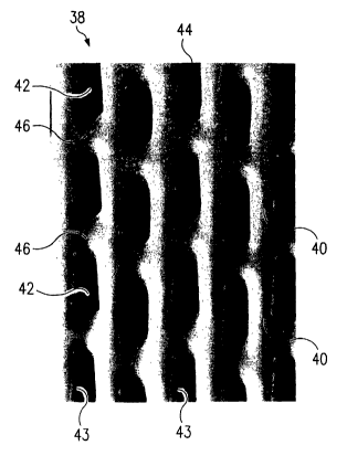
Refernng now to Figure 4, a multi-plane VFF 38 is shown wherein the highest
plane is the upper surface ofthe SD lands 40. VFF 38 is produced from a
forming screen
having an elliptical pattern with MD alignment of the major axes 42 of cells
43. The
pattern shown in Figure 6 is a 40 mesh pattern. Cells 43 of vacuum formed film
38
measure about 750,um in the SD or major axis 42 direction and about 250,um in
the TD
or minor axis 44 direction. The thickness of the apertures 43, which are from
top to
bottom of the three-dimensional cells 43, i.e, loft, is about 345,um. The VFF
38 has an
open area of 14.5%. Therefore, the loft to % open area ratio of the VFF 38 is
about 24.
The VFF 38 has a rewet value of .08 grams. The variance between the upper
surface of
the SD lands 40 and the TD lands 46 in the bi-planar material 38 is about
20,um.
Referring now to Figures SA and SB, Figures SA and SB show another
embodiment of VFF that shall be referred to as a VFF having "Boat Shape Cells"
(BSC)
50. The "Boat Shaped Cell" embodiment 50 preferably has a mesh count of 40.
"Boat
Shape Cell" refers to the oval shape apertures 52 having rounded tips.
Apertures 52 have
a major axis 54 and a minor axis 56. Preferably, the ratio of length of major
axis 54 to
minor axis 56 of the cells is about 1.75:1. It has been found that rounding
off the
extremities of either an oval shaped cell, as shown in Figures SA and SB, or
an ellipse
shaped cell, as shown in Figures 3 and 4, further enhances the STI, especially
in a single
plane material. The BSC embodiment 50 of Figures SA and SB has cells 50 having
a
13
CA 02446731 2003-11-07
WO 02/098338 PCT/US02/13160
length along the major axis 54 of about 425,um and a length along the minor
axis of about
240,um. The BSC film 50 has a loft of 315,um and an open area of 22%, which
yields a
loft to % open area ratio of 14 and a rewet value of 0.15 grams. Of course,
the above
dimensions are illustrative and other dimensions of may be used.
An additional feature of the BSC embodiment 50 is that the major axis 54 of
the
boat shaped cells or three dimensional apertures 52 are aligned in the SD but
are not
commonly aligned with each other, i.e., the cells 52 are presented in a
"staggered"
arrangement. Consequently, SD lands 58 are not straight as is the case with SD
lands 34
(Fig. 3) and 40 (Fig. 4) of VFF films 26 and 38, respectively. A film having
bi-planar
lands, e.g, the embodiment shown in Figure 1A and 1B, are not preferred for
the
staggered BSC embodiment because it has been found that bi-planar lands are
best
achieved when all the SD lands, e.g. 34 and 40 are co-aligned with each other.
Despite
these less preferred variations, it has been found that panelists have still
been able to
derive a noticeable STI from the 40 mesh BSC (when counting the mesh in the
TD)
embodiment 50. Application of a random matte texture to the lands further
enhances the
material and slightly improves a panel's STI rating of the material.
While it is known that the addition of any of the aforementioned VFF-capable
textures to the lands will contribute to improvement ofthe tactile impression
and eliminate
any perceptive triggers that are indicative of a plastic type material, it has
surprisingly been
found that "micro-ridges" (MR) alone can create a perceptible STI. Referring
to Figures
6A, 6B and 7, microphotographs of a top view of VFF 100 (the side to the user;
Fig. 6A)
and a bottom view of VF 100 (the side away from the user; Fig. 6B), and an
expanded
graphic in cross-section of VFF 100 (Fig. 7) are given to show the MR of this
invention.
VFF 100 has a 40 hex pattern. To form textures on lands 102 of VFF 100, lands
on a
forming screen that is used to make VFF 100 are ground to be substantially
flat to accept
the artwork for etching the micro-ridges in the land region of the forming
screen. As a
result, lands 102, formed between apertures 104, are imparted with micro-
ridges 106.
The machine direction (MD) or stroking direction (SD) is indicated by arrow
108.
Micro-ridges 106 preferably have individual distinction with a range of height
and
spacing and have an optimum STI effect when aligned on a bias, i.e., at offset
angle 110
to the SD 108. Offset angle 110 may be 5° to 80° to achieve some
effect, but the
14
CA 02446731 2003-11-07
WO 02/098338 PCT/US02/13160
preferred range for offset angle 110 is from 30 ° to 60 °, and
ideally 4S ° is used. The
height ofthe MR 106 can range from S,um to 7S,um, but the preferred range is
from Sam
to 3S,um. Ideally, MR 106 have a height of 20~cm. Spacing between micro-ridges
106
can range from 2S,um to 2SO,um, but more preferably range from SO,um to
lSO,um. Most
preferably, a 9S,um spacing is used. The micro-ridges 106 must also maintain
"individuality". If micro-ridges 106 become interconnected, then micro-ridges
106 will
not create the desired STI but rather the micro-ridges 106 will exhibit a
planar and plastic-
like feel instead.
TEST DATA
Various formed films were tested by ten panelists for silky tactile impression
(STI). The results are presented in Table 2, below. The panel method was based
upon
the AATCC (1997) Evaluation Procedure S, Fabric Hand: Guidelines for the
Subjective
Evaluation ofFabric, a Technical Manual ofthe American Association of Textile
Chemists
and Colorists, Volume 72 (pp.3 S2-3 S4), Research Triangle Park, NC; and, ASTM
(1968)
1 S Manual on Sensory Testing Methods, ASTM Special Technical Bulletin 434,
1968,
pp.3-S.
The evaluation procedure utilized a common pad of standard thickness and
material yielding a standard compressibility. Values for thickness and
compressibility are
not particularly important, so long as the values are consistent. The pad was
cut into 3.81
cm by 7. 62 cm ( 1. S inch by 3.0 inch) rectangles. The films were wrapped
fully around and
taped closed, much like wrapping a gift, leaving on one side a continuous,
smooth area
ofmaterial. The continuous, smooth side comprise the tested side. Panelists
washed their
hands so that the samples were not tainted; tainting potentially creating an
anomalous
variance between panelist one and panelist ten, as the samples are passed from
one
panelist to another.
The samples were coded by an identifier, such as a number or letter, but no
information was provided to avoid any pre-biasing of a panelist. The panelists
were asked
to rate the samples from 1 to 10 with 1 being the silkiest and 10 being not
silky.
All but one of the products in the test data of Table 2 below are apertured
film
3 0 embodiments, except for "Unicharm's TS Threads on NW". The Unicharm
product is not
1S
CA 02446731 2003-11-07
WO 02/098338 PCT/US02/13160
a formed film product, but it has been added to Table 2 because it is
recognized as
succeeding as a feminine napkin topsheet in Asia and is known to be viewed as
triggering
a favorable STI. It is constructed by an unknown method wherein synthetic silk
threads
are bonded to a top plane (skin contact side) of a nonwoven web. Holes are
punched
through the material, apparently to increase the rate of fluid acquisition.
Its fluid
acquisition rate value is believed to be over 3.0 grams. The Unicharm product
is included
here to assist in obtaining a stronger reading on the panel test's apparent
line of separation
between STt and non-STI materials. Also included for that purpose is Comfort
Silk~.
Comfort Silk~ is a mechanically formed apertured film but is not a VFF. It too
has been accepted as "Silky" in the marketplace. Therefore, the inclusion of
Comfort
Silk~ aids in making STI and non-STI distinctions.
In reviewing the data, it is commonly accepted that an average ranking of a
film
by ten panelists of a value of <_ 5.0 indicates a STI is discernable. The
number of No. 1
rankings given by panelists can also serve as an indication that an STI has
been'triggered'.
TABLE 2
TestersMD Ellipse40Hex 40 Unicharm'sComfortsilkAlways Equate
FlatlandBSC TS
w/Micro Threads
Ridges on NW
1 6 3 2 5 1 8 10
2 4 1 3 7 2 10 6
3 1 2 4 5 3 9 10
4 2 1 6 3 5 8 10
5 3 1 6 4 5 10 8
6 5 1 3 6 2 9 7
7 1 4 7 6 3 5 10
8 2 1 6 4 5 8 10
9 6 1 5 4 2 10 8
10 5 3 1 6 2 9 10
AVG. 3.5 1.8 4.3 5 3 8.6 8.9
Rate the samples from 1 to 10 for Silkiness Testing.
1 = "Silkiest" : 10 = "not Silky"
16
CA 02446731 2003-11-07
WO 02/098338 PCT/US02/13160
Another important test for comparing various films is a "Rewet Test". For
testing
rewet a test fluid comprising two parts Pepto-Bismol~ and one part distilled
water was
used. The sample assembly consisted of a 12.7 cm by 12.7 cm (5 inch by 5 inch)
piece of
vacuum formed film or nonwoven topsheet placed with the user side up and the
garment
side dawn over 3 plies of absorbent medium. An amount of 2-ml test fluid was
delivered
through a pipette onto the center surface of the topsheet. The time, in
seconds, taken for
all of the liquid to penetrate through the topsheet was recorded with a
stopwatch. This
portion of the test indicates the fluid acquisition rate: After the initial
insult, an additional
15-ml of the test fluid was delivered to the center surface of the topsheet.
An 3.63 kg (8
Ibs) rewet weight with a 10.16 cm by 10.16 cm (4 inch by 4 inch) footing was
placed on
the top of the topsheet for 3 minutes for the fluid to thoroughly spread out
into the core
pads. Then, two pre-weighted pickup papers were pressed against the topsheet
with the
3.63 kg (8 lbs) rewet weight for an additional 2 minutes. The amount of weight
increase
of the pickup papers was measured in grams as the rewet amount, which reflects
the
amount of fluid that successfully reversed flow and overcame the spatial
separation of the
topsheet material.. It has been found that data using this fluid for both
acquisition rate and
rewet values correlates well to comparative data generated from the same VFF
materials
tested by this method and by undisclosed methods used by major corporations
who
produce feminine napkin products.
Table 3, below, compares existing products and shows that embodiments of this
invention provide a desirable STI, and also maintain a L/OA Ratio that
exhibits functional
rewet:
TABLE 3
Product Loft, Open Area,L/OA RatioRewet, STI (Y/N)
~m grams
Always 550 32.0 17.0 0.05 N
Equate 455 28.5 16.0 0.15 N
ConlfortSilk115 28.5 4.0 1.25 Y
SD Ellipse345 14.5 23.8 0.08 Y
38
40 Mesh 315 22.0 14.3 0.15 Y
BSC
50
17
CA 02446731 2003-11-07
WO 02/098338 PCT/US02/13160
It is thus believed that the operation and construction ofthe present
invention will
be apparent from the foregoing description. While the apparatus and
compositions shown
or described have been characterized as being preferred it will be obvious
that various
changes and modifications rnay be made therein without departing from the
spirit and
scope of the invention as defined in the following claims.
18