Note: Descriptions are shown in the official language in which they were submitted.
CA 02449468 2003-12-04
WO 02/098282 PCT/US02/17704
Cardiac Stimulating Apparatus Having a
Blood Clot Filter and Atrial Pacer
Field Of The Invention
The present invention relates generally to a device that deters migration
of emboli from an atrial appendage into the vascular system of a patient, and
more particularly to a device that includes a filter to deter such migration
and a
pacer to deter the formation of emboli such as blood clots within the atrial
appendage.
l0 Background Of The Invention
Non-rheumatic atrial fibrillation (NRAF) is associated with
thromboembolic complications such as strokes. For example, when a thrombus
or embolus occludes a vessel supplying blood to the brain, a stroke may result
causing temporary or lasting paralysis of a part of the body or, in severe
cases,
death. Blockage of other blood vessels can occur as well causing attendant
health concerns, including heart attack or gangrene. Presently, a five percent
risk of stroke per year in a largely aging population causes NRAF to be a
significant health concern. Given the potentially irreversible and destructive
nature of such blood vessel occlusion, safe and effective methods are needed
to
eliminate embolic material like blood clots from the vascular system, some of
CA 02449468 2003-12-04
WO 02/098282 PCT/US02/17704
which may be formed within an atrial appendage of the heart.
The left atrial appendage forms a small protrusion which is attached to
the lateral wall of the left atrium between the mitral valve and the root of
the left
pulmonary vein and normally contracts along with the left atrium. Atrial
fibrillation is a cardiac condition wherein the atria beat faster than the
ventricles,
causing the ventricles to contract irregularly and consequently eject less
blood
into the vascular system. A major problem associated with atrial fibrillation
is
pooling of blood in the left atrial appendage.
During NRAF the left atrial appendage may not fully contract, leaving
stagnant blood within the left atrial appendage. In turn, the stagnant blood
may
create a condition favorable to the formation of blood clots within the left
atrial
appendage. Such clots may travel from the left atrial appendage into the left
atrium and into the vascular system, thereby increasing the danger of stroke
or
cardiac blockage.
Traditional treatments to mitigate the risks posed by blood clots include
the use of anticoagulants to dissolve the clots. For example, recently
published
results from stroke prevention trials suggest that prophylaxis with
anticoagulation is beneficial to patients with non-rheumatic, non-valvular
atrial
fibrillation. Current therapeutic interventions include anticoagulation with
coumedin. In addition, therapeutic interventions include the use of atrial
rate
regulating medications. However, both of these treatment approaches pose
potential complications such as internal bleeding, as well as other negative
side
effects caused by the rate regulating therapeutic agents.
In addition to pharmacological treatments, complex radical surgical
2
CA 02449468 2003-12-04
WO 02/098282 PCT/US02/17704
methods are available to treat atrial fibrillation. Such treatments include,
for
example, atrial incisions or removal of the left atrial appendage, which have
been attempted in a limited, experimental way. Such approaches are highly
invasive and pose a risk of mortality to the patient. Thus, a pressing need
exists
for means by which the formation of blood clots the left atrial appendage is
substantially deterred while preventing the migration of any blood clots which
may form from entering the vascular system.
U.S. Patent 6,152,144 to Lesh et al., for example, discloses a device and
method for obliterating or occluding a body cavity or passageway.
Specifically,
the patent to Lesh is directed to a device and method for obliterating or
occluding the left atrial appendage of a patient's heart. In one embodiment,
L.esh et al. disclose a frame structure having a barner or mesh material
disposed
over it to act as a barrier to the passage of embolic material.
However, Lesh et al. do not disclose a device or method suited to treat
atrial fibrillation, or other arrhythmias of the heart, to thereby prevent the
formation of clots in the left atrial appendage. As such, the barrier
embodiment
of Lesh et al. permits ongoing formation of clots within the left atrial
appendage,
which may eventually occlude the barrier material to prevent fluid flow as
well
as embolic material flow through the occluded barrier. Such a situation may
present a health concern as the left atrial appendage contracts and the blood
enclosed therein is unable to exit the left atrial appendage. Such contraction
may result in an increased pressure in the left atrial appendage capable of
weakening the wall of the left atrial appendage. Additionally, as the barrier
embodiment of Lesh et al. does not prevent the formation of clots, it is
possible
3
CA 02449468 2003-12-04
WO 02/098282 PCT/US02/17704
that the volume of the left atrial appendage may eventually be filled with
coagulated blood. Thus, filtering alone poses possible added health concerns.
Regarding the treatment of atrial fibrillation, it is known to use a
pacemaker, for example, as disclosed in U.S. Patent 6,178,351 Bl to Mower.
Mower discloses a pacemaker that is capable of pacing the atria from multiple
sites, but does not address prevention of migration of embolic material within
the vascular system. Moreover, neither Mower nor Lesh suggests combining a
pacer with an embolic barner for use in the heart.
Accordingly, there is a need for an apparatus for mitigating the risks
associated with emboli originating in the left atrial appendage and also for
reducing the tendency of such emboli, such as blood clots, to form therein.
Summar~r of the Invention
An apparatus is provided for deterring the formation and migration of
blood clots from an atrial appendage, such as a left or right atrial
appendage,
into the blood vessel system, i.e. vascular system, of a patient. In
particular, an
apparatus of the present invention comprises an atrial pacer to treat non-
rheumatic atrial fibrillation (NRAF) or other arrhythmias of an atrial
appendage
so that the formation of blood clots within such atrial appendage is decreased
or
eliminated. In addition, the apparatus provides a blood clot filter to deter
the
migration of blood clots from an atrial appendage into the blood vessel system
of a patient.
More specifically, the apparatus comprises a filter for reducing the
transport of emboli from an atrial appendage to an atrium of the heart. The
filter
4
CA 02449468 2003-12-04
WO 02/098282 PCT/US02/17704
is formed to provide a structure suitable for separating blood clots from the
blood and for reducing passage of blood clots from the atrial appendage into
the
atrium and general circulation. In accordance with one aspect of the
invention,
the filter can take the form of a plurality of spokes extending outwardly from
the
atrial pacer. In another aspect, the filter can take the form of a mesh having
pores sized to deter the passage of blood clots.
In accordance with another aspect of the invention, the apparatus
comprises an atrial pacer which supports the filter between an atrial
appendage
and the atrium. The atrial pacer is adapted to be in contact with a wall of
the
atrial appendage so the atrial pacer may detect and reduce atrial fibrillation
in
the atrial appendage. The pacer also includes a sensor which may form an
integral part of the atrial pacer for sensing fibrillation in the atrial
appendage. In
an alternative arrangement, the sensor may be adapted to be positioned
externally to the heart. In this external arrangement, a lead wire may be
provided between the sensor and the atrial wall, to provide sensing contact
between the sensor and the atrial wall. The atrial pacer also comprises a
stimulator for stimulating the atrial appendage. The simulator may take the
form of an electrode for making electrical contact with the wall of the atrial
appendage to apply stimulating signals to the atrial appendage. The stimulator
may be activated in response to a signal from the sensor indicating the
presence
of NRAF, or other arrythmias, in the atrial appendage.
A control unit adapted to be positioned externally to the heart may
optionally be provided for controlling the atrial pacer. The control unit may
communicate with the sensor and/or the stimulator using a lead wire or
wireless
5
CA 02449468 2003-12-04
WO 02/098282 PCT/US02/17704
technology. In addition, the sensor may be disposed within the control unit.
For
example, in the arrangement where the sensor is positioned externally to the
heart, the sensor may be incorporated within the control unit.
Brief Description Of The Drawings
The foregoing summary and the following detailed description of the
preferred embodiments of the present invention will be best understood when
read in conjunction with the appended drawings, in which:
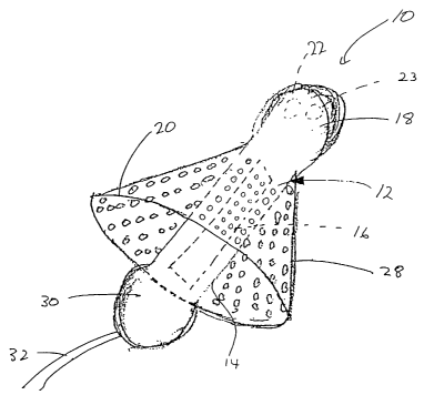
Figure 1 is a schematic perspective view showing an exemplary device of
the present invention having a mesh filter;
Figure 2 is a schematic perspective view showing an exemplary device of
the present invention having a filter which includes a plurality of spokes;
Figure 3 is a schematic view of the exemplary device shown in Figure 1
disposed within a left atrial appendage;
Figure 4 is a schematic view of the exemplary device shown in Figure 2
disposed within a left atrial appendage;
Figure 5 is a schematic block diagram of a first exemplary configuration
of an atrial pacer of the present invention having a control unit which
includes a
sensor and lead wire for detecting a selected condition of the heart;
Figure 6 is a block diagram of a second exemplary configuration of an
atrial pacer of the present invention having a control unit for communication
with stimulator and sensor;
Figure 7 is a block diagram of a rechargeable configuration of an atrial
pacer of the present invention;
6
CA 02449468 2003-12-04
WO 02/098282 PCT/US02/17704
Figure 8 is a schematic view of the exemplary device shown in Figure 1
with the filter collapsed against the body of the device; and
Figure 9 is a schematic view of the exemplary device shown in Figure 2
with the spokes collapsed against the body of the device.
Detailed Description Of The Invention
A cardiac stimulating apparatus 10, 100 is provided for substantially
reducing the formation of blood clots in an atrial appendage of a heart, such
as
the left atrial appendage 210, and reducing the migration of such clots into
the
blood vessel system of a patient. The apparatus 10, 100 comprises a filtration
device 28, 124 to reduce migration of embolic material, such as blood clots or
the like. In addition, the apparatus 10, 100 includes an atrial pacer 12, 112
to
treat arrythmias, such as non-rheumatic atrial fibrillation (NRAF), of the
left
atrial appendage 210 to deter the formation blood clots within the left atrial
appendage 210. Figures 1-4 depict the general structure of a cardiac
stimulating
apparatus of the present invention, illustrating the cooperation between the
atrial
pacer 12, 112 and the filtration device, such as filter 28 or spokes 124.
Turning now to Figs. 1 and 3, an embodiment of the present invention is
shown in which a cardiac stimulating apparatus 10 comprises an atrial pacer 12
having an elongated generally tubular body 14 having first and second opposing
ends 18, 30. The first end 18 of the atrial pacer 12 is adapted to contact the
wall
of the left atrial appendage 210 to support the cardiac stimulating apparatus
10
within the left atrial appendage 210. The first end 18 may include a sensing
device 22 optionally disposed therein to detect NRAF or other arrhythmias in
7
CA 02449468 2003-12-04
WO 02/098282 PCT/US02/17704
the left atrial appendage 210. In such a configuration, the sensing device 22
is
adapted to be in sensing contact with the wall of the left atrial appendage
210.
The first end 18 of the atrial pacer 12 also includes a stimulating device 23
for
stimulating the left atrial appendage 210 in response to detection of NRAF by
a
detector, such as sensing device 22. The stimulating device 23 includes an
electrode adapted to be in electrical contact with the wall of the atrial
appendage
210 for applying stimulating signals to the atrial appendage 210. By
application
of an appropriate stimulating signal, NRAF can be reduced or eliminated
thereby reducing the tendency of blood within the left atrial appendage 210 to
form blood clots. The sensing device 22 and stimulating device 23 may
comprise components known for use in atrial pacers.
Extending outwardly from the elongated generally tubular body 14, a
filtration device is provided to deter the migration of blood clots from the
left
atrial appendage 210 into the left atrium 200 of the heart. As shown in Fig.
l,
an embodiment of the filtration device may take the form of a mesh-like or
sieve-like filter 28. The filter 28 may have a generally conical shape as
shown,
for example, with the narrower end of the conical filter 28 attached to the
atrial
pacer 12 proximate to the first end 18 of the atrial pacer 12. Alternatively,
the
filter 28 may be attached to the atrial pacer 12 at any point along the
elongated
body 14. The filter 28 may have any shape suited to substantially fill the
opening defined by the intersection of the left atrial appendage 210 and the
left
atrium 200, such as a portion of a sphere, flat sheet, or other shape.
The mesh-like material of the filter 28 may be formed from a metal, such
as a stainless-steel, for example. Alternatively, the filter 28 may be formed
from
8
CA 02449468 2003-12-04
WO 02/098282 PCT/US02/17704
a polymeric material, such as a Nylon or Dacron mesh. Other suitable materials
such as PTFE or polyamides may also be used. In particular, it is preferable
that
the filter 28 be formed of a resilient material capable of being collapsed
about
the body 14 of the atrial pacer 12, as shown in Fig. 8, to facilitate
introduction of
the cardiac stimulating device 10 into a patient, for example, via a catheter.
The
resilient material is chosen such that upon removal of the cardiac stimulating
device 10 from the catheter, the filter 28 expands to a desired shape and size
to
permit the opening of the left atrial appendage 210 to be substantially
sealed.
Regardless of the material from which the filter 28 is formed, the filter 28
is
formed to provide pores having a transverse dimensions of about 1 mm or other
size sufficiently small to prevent the passage of blood clots or other
thromboembolic material of like or greater size. In particular, it may be
desirable for the pore size to have a transverse dimension up to about 0.1 mm.
The wider end of the filter 28 includes a rim portion 20 which defines the
base of the filter 28. The rim portion 20 is sized to circumscribe the opening
between the left atrial appendage 210 and left atrium 200, so that emplacement
the cardiac stimulating device 10 in the left atrial appendage 210 generally
positions the rim portion 20 near the opening left atrial appendage 210 so as
to
form and maintain a seal therewith. To effect and maintain such a seal, the
rim
portion 20 may be formed of or covered by a soft polymer material. The rim
portion 20 may have a transverse dimension of about 2 to 40 mm, preferably
about 25 to 35 mm. The transverse dimension of the rim portion 20 should be
selected with regard to the size of the left atrial appendage opening, which
may
vary among patients, especially those patients having heart disease related
9
CA 02449468 2003-12-04
WO 02/098282 PCT/US02/17704
conditions.
The rim portion 20 may also include a plurality of holes through which
sutures may be placed to anchor the rim portion 20 proximate to the opening of
the left atrial appendage 210. Alternatively or additionally, the rim portion
20
may have a spring-like action which causes the rim portion 20 to expand
generally radially outward from the longitudinal axis of the atrial pacer 12,
so
that the rim portion 20 applies pressure against a region proximate the
opening
of the left atrial appendage 210 to form a seal proximate the opening of the
left
atrial appendage 210. For example, the rim portion 20 may be formed of a
shape memory metal, such as NiTi, having a memorized shape larger than that
of the opening of the left atrial appendage 210 to supply the radially outward
pressure on the opening. The filter 28 is attached to the atrial pacer 12 at
such a
location so as to permit the rim portion 20 to substantially form a seal
within the
left atrial appendage opening and to permit the first end 18 of the atrial
pacer 12
to contact the wall of the atrial appendage 210.
Referring now to Figs. 2 and 4, an alternative embodiment of the cardiac
stimulating apparatus 100 is shown where the filtration device comprises a
plurality of spokes 124 extending generally radially outwardly from the atrial
pacer 112, to deter the migration of blood clots from the left atrial
appendage
210 of the heart to the left atrium 200 of the heart. The atrial pacer 112 of
the
alternative embodiment comprises an elongated generally tubular body 114
having first and second ends 118, 130, a stimulating device 123, and an
optional
sensing device 122 similar to like components 23 and 22 described above with
regard to the previous embodiment.
CA 02449468 2003-12-04
WO 02/098282 PCT/US02/17704
The spokes 124 each comprise a first end 125 attached to the elongated
body 114 of the atrial pacer 112 and a second end 127 of the spokes 124 for
engaging a region of the heart in the vicinity of the left atrial appendage
210.
The second end 127 of the spokes 124 may terminate in a hook-like tine 126
formed to anchor the spokes 124 and retain the atrial pacer 112 within the
left
atrial appendage 210. In addition, all or some of the second ends 127 of the
spokes 124 may include a hole suitable for placing a suture therethrough for
attachment to the left atrial appendage 210. The number of spokes 124
employed should be sufficiently numerous to create interstices between the
spokes 124 sufficiently small to deter the passage of embolic material through
the interstices.
The first ends 125 of the plurality a spokes 124 may be attached to the
body 114 of the atrial pacer 112 at a common distance from the first end 118
of
the atrial pacer 112. Alternatively, the first ends 125 of the plurality of
spokes
124 may be attached to the body 114 of the atrial pacer 112 at varying
distances
from the first end 118 of the atrial pacer 112. Providing spokes 124 at a
variety
of distances from the first end 118 of the atrial pacer 112 may be useful to
create
a tortuous path to deter the flow of embolic material. For example, a first
set of
spokes 124 may have first ends 125 adjoining the atrial pacer 112 at a common
distance from the first end 118 around the circumference of the atrial pacer
112.
A second set of spokes may have first ends adjoining the atrial pacer 112 at a
further distance from the first end 118 of the atrial pacer 112 than the first
set of
spokes 124. In addition, the second set of spokes may be oriented
circumferentially to overlap with the interstices formed among the first set
of
11
CA 02449468 2003-12-04
WO 02/098282 PCT/US02/17704
spokes 124, as viewed from the first end 118 of the atrial pacer 112.
Likewise,
additional set of spokes 124 may be included to effect additional blockage of
embolic material flow. Moreover, some or all of the spokes 124 may extend
outwardly from the atrial pacer 112 along non-radial directions, to enhance
blockage of embolic material.
The spokes 124 may be formed of any suitable material such as a metal
or polymeric material like those described above with regard to the mesh-like
filter 28. It is also desirable that the spokes 124 be sufficiently pliable to
permit
the spokes 124 to be disposed along the body 114 of the atrial pacer 112, as
shown in Fig. 9, while the cardiac stimulating device 100 is placed into a
patient
via a catheter.
In addition, it is desirable that the spokes 124 be sufficiently resilient so
that they expand away from the body 114 of the atrial pacer 112 once removed
from the catheter, permitting the spokes 124 to engage the wall of left atrial
appendage 210. In addition, the spokes 124 are formed sufficiently long and
disposed at an angle away from the body 114 of the atrial pacer 112 to cause
the
second ends 127 of the spokes 124 to be biased against the wall of the left
atrial
appendage 210 to retain the cardiac stimulating device 100 in position. For
example, the spokes 125 may have a length to allow the second ends 127 of the
spokes 124 to terminate proximate the left atrial appendage opening. The
spokes 124 are attached to the atrial pacer 112 at such a location as to
permit the
spokes 124 to partially occlude the opening of the left atrial appendage and
to
permit the first end 118 of the atrial pacer 112 to contact the wall of the
atrial
appendage 210.
12
CA 02449468 2003-12-04
WO 02/098282 PCT/US02/17704
In each of the above embodiments, the atrial pacer 12, 112 may include a
power source 16, 116, such as a rechargeable battery, within the generally
elongated body 14, 114 along with appropriate circuitry known for the
operation
of atrial sensing and stimulating devices. Alternatively or additionally, the
cardiac stimulating device 10, 100 may include a lead wire 32, 132 to provide
power and/or a control signal to the atrial pacer 12, 112 from a remote
device. A
control unit for use external to the left atrial appendage 210, or external to
a
patient's body, may be provided for housing circuitry of the atrial pacer 12,
112.
Providing such a control unit may also be desirable, since inclusion of
control
circuitry therein may permit the atrial pacer 12, 112 to have a smaller
overall the
size.
Referring to Figs. 5-7, three exemplary embodiments are shown of
device arrangements which include remote control and/or power supply units.
In particular, with regard to Fig. 5, a control unit 302 is shown for
controlling
and powering the stimulator 308 of an atrial pacer. The stimulator 308 may
correspond to the stimulating devices 23, 123 depicted in Figs. 1 and 2 as
described above. In the configuration of Fig. 5, a sensor 304 is incorporated
in a
remotely located control unit 302 rather than in the elongated body 14, 114 of
the atrial pacer 12, 112. The sensor 304 is in sensing contact with the left
atrial
appendage 210 via lead wire 306 to detect NRAF in the atrial appendage 210.
Hence, for this configuration the sensing device 22, 122 described above as
being disposed within the first end 18, 118 of the atrial pacer 12,112 is not
required to be disposed therein.
The control unit 302 further includes control circuitry 310 for processing
13
CA 02449468 2003-12-04
WO 02/098282 PCT/US02/17704
the signal detected by the sensor 304 and controlling the stimulator 308 in
response to the detected signal. For example, when the control circuitry 310
receives a signal from the sensor 304 indicative of NRAF of the left atrial
appendage 210, the control circuitry delivers a control signal to the
stimulator
308 to cause the stimulator 308 to stimulate the left atrial appendage 210 to
alleviate the NRAF. Hence, by correcting NRAF, formation of blood clots in
the left atrial appendage 210 is reduced by limiting the presence of stagnant
blood in the left atrial appendage 210. The control unit 302 communicates with
the stimulator 308 via an optional lead wire 309 or via wireless
communication.
Wireless communication can be effected via optional antennas 314, 315
connected to the control unit 302 and the stimulator 308, respectively. The
antenna 315 of the stimulator 308 may be disposed, for example, at the second
end 30, 130 of the atrial pacer 12, 112. The control unit 302 may include a
power source 312 to power the control unit 302 and to optionally power the
stimulator 308 via lead wire 307.
Referring to Fig. 6, a further embodiment of the present invention is
shown which is substantially similar to that shown in Fig. 5. The embodiment
of Fig. 6 differs from Fig. 5 in that the control unit 402 of Fig. 6 does not
include a sensor. Instead, a sensor 404 is provided in the elongated body 14,
114 of the atrial pacer 12, 112 along with a stimulator 408. Such a sensor 404
may correspond to the sensing devices 22, 122 shown in Figs. 1 and 2 and
described above. Since the sensor 404 and stimulator 408 are both disposed
within the body 14, 114 of the atrial pacer 12, 112, the sensor 404 and
stimulator
408 may communicate directly with each other so that the stimulator 408 may
14
CA 02449468 2003-12-04
WO 02/098282 PCT/US02/17704
stimulate left atrial appendage 210 in response to the detection of NRAF by
the
sensor 404. Alternatively, to minimize the size of the atrial pacer, control
circuitry may be provided in a remote control unit 402 to receive data from
the
sensor 404, to process such data, and control the stimulator 408 in response
to
such data. Communication between the control unit 402 and the stimulator 408
and sensor 404 may be effected via an optional lead wire 409 or via wireless
communication using optional antennas 414, 415, in a similar manner to that
described above with regard to the embodiment of Fig. 5.
In addition, as shown in Fig. 7, the atrial pacer 512 may be configured to
be recharged by a remote charger 506. In such an embodiment, the atrial pacer
512 includes a first electrical coil 502 electrically coupled to an energizer
unit
516, such as a battery, of the atrial pacer 512. The recharger 506 has a
corresponding second electrical coil 504 which may be electromagnetically
coupled to the first coil 502 to transmit electromagnetic energy thereto from
the
charger 506, through the patient's skin 508, and thence into the energizer
unit
516 of the atrial pacer 512.
After insertion of the cardiac stimulating device 10, 100 into the heart so
that the filtration device 28, 126 expands and sensing device 22, 122 or
sensor
304, 404 is placed in sensing contact with the left atrial appendage 210, the
cardiac stimulating device 10, 100 monitors for the presence of NRAF. Upon
detection of NRAF, the stimulator 23, 123 applies a correcting stimulating
electrical signal to the left atrial appendage 210 in response to the detected
NRAF condition. By such treatment of the left atrial appendage 210 to
minimize NRAF, the formation of blood clots attributable to NRAF is
CA 02449468 2003-12-04
WO 02/098282 PCT/US02/17704
minimized. In addition, the presence of the filtration device 28, 126 provides
continuous filtration of the blood exiting the left atrial appendage 210, so
as to
prevent the egress of emboli therefrom.
These and other advantages of the present invention will be apparent to
those skilled in the art. Accordingly, it will be recognized by those skilled
in the
art that changes or modifications may be made to the above-described
embodiments without departing from the broad inventive concepts of the
invention. For example, the atrial pacer could be replaced and/or adapted to
function as a ventricular defibrillator to treat ventricular tachycardia.
Likewise,
the atrial pacer could be replaced by a device that functions as a combined
atrial
pacer and ventricular defibrillator. It should therefore be understood that
this
invention is not limited to the particular embodiments described herein, but
is
intended to include all changes and modifications that are within the scope
and
spirit of the invention as set forth in the claims.
16