Note: Descriptions are shown in the official language in which they were submitted.
CA 02461109 2004-03-15
21667
Lancing aid comprising a lancet system that is protected against re-use
The invention concerns a lancet system that can be used in a lancing aid for
withdrawing blood for diagnostic purposes. In a variety of diseases it is
necessary to
examine human blood for an analyte contained therein. In many cases this only
requires the withdrawal of a small amount of blood in the form of a blood drop
by
producing a small puncture wound. A particularly important example of such a
case
is diabetes in which the glucose content of blood has to be examined at
regular
intervals. Blood may also for example be examined with regard to coagulation
parameters, triglycerides, HbAlc or lactate. Blood lancet devices which
consist of a
lancing aid and a tailor-made replaceable lancet are usually used to produce
the
required puncture wounds. The housing of the lancet instrument contains a
lancet
holder in which one interchangeable lancet can be inserted. During the lancing
operation the lancet holder is rapidly moved in a lancing direction by a
lancet drive of
the lancet which is also integrated into the lancing aid until the needle tip
emerges
from an exit opening provided at the front end of the lancing aid and produces
a
small puncture wound in the part of the body that is pressed against the front
end.
Afterwards the lancet holder containing the lancet is moved back in the
opposite
direction to lancing.
Small, easy-to-handle blood collection devices, so-called lancing aids that
can be
easily and reliably operated by the user and enable a part of the body to be
lanced in
an almost painless manner are now routinely used. In order to avoid infections
especially in hospitals, the lancets are disposable elements intended for
single use.
After a lancet has been used once, the lancet is removed after the lancing
operation or
ejected from the device and discarded as refuse. In such a case the exposed
needles in
a refuse container may lead to injury during waste disposal resulting in a
contamination of other persons by the used lancet. Such contamination may lead
to
infections and thus some countries are planning to impose a ban on blood
collection
systems in which the needle tip is freely accessible after use. In addition to
a risk of
CA 02461109 2004-03-15
-2-
injury during waste disposal there is also a risk that a used lancet may be
accidentally
re-used. This is particularly relevant for hospitals in which a lancing aid is
used for
several patients since such inadvertence of the nursing staff could lead to a
patient
being contaminated with the blood of a previous patient.
In addition to the use of blood lancet devices by medical staff, lancing aids
are also
used by laymen in the so-called home-monitoring field. This is particularly
the case
for monitoring the treatment of diabetics. Thus it has been found in the
treatment of
diabetics that serious damage associated with diabetes such as loss of sight
can be
substantially reduced when the glucose concentration in the blood of the
diabetic is
determined frequently and up to five times daily and the insulin injection is
exactly
adjusted on the basis of these measurements. Lancing aids which enable the
diabetic
to carry out such a blood examination are used for home-monitoring in order to
carry out such frequent measurements. The resulting requirements for a blood
lancet
device are a simple handling when inserting new lancets and a reliable
ejection of
used lancets in addition to a simple handling when triggering the lancing
operation
and a relatively painless puncture. Lancet replacement should on the one hand
be as
simple as possible and, on the other hand, ensure the utmost safety with
regard to
unintentional injury of the user or other persons. Although in the home-
monitoring
field it is conceivable that a lancet, once inserted, is used several times
for lancing by
the same user, even in this case an accidental re-use of an ejected lancet
should be
prevented once the user has decided to discard the lancet. Furthermore other
persons
in particular should be reliably protected from the discarded lancets for
example
during waste disposal.
In the prior art the tip of the needle is usually surrounded by a tip cover
made of
plastic when the lancet is inserted which allows a safe insertion of the
lancet. When
the lancet is inserted, the tip cover is removed to expose the sharp tip of
the needle
for the lancing operation (US 5,628,765). However, due to the exposed needle
tip
there is a risk of accidental injury and the tip may become damaged. The
lancet is
removed from the lancing aid after one or several lancing operations. This can
either
be carried out manually in which case there is a high risk of injury by the
needle tip or
by an automatic ejection mechanism.
CA 02461109 2004-03-15
-3-
A blood lancet device is disclosed in the patent EP 0 565 970 in which the
lancet is
ejected from the lancet holder by means of an ejecting rod. The user can
operate the
ejecting rod by pressing a corresponding button.
Furthermore an ejecting mechanism is described in the patent document US
4,442,836 where the needle is automatically released when the lancing aid is
retensioned so that the used lancet is discarded after each lancing operation.
Such
ejecting mechanisms require a relatively high degree of additional
engineering.
Moreover multiple use of an already inserted lancet system is not possible
which is,
however, often desired by customers especially in the home-monitoring field.
Another major disadvantage of the described prior art is that the needle tip
is
unprotected after the lancet has been ejected resulting in a risk of injury as
described
above.
In order to facilitate the safe removal of a used lancet, blood collection
systems are
also described in the prior art which ensure the needle tip is protected after
ejecting
the lancet. This is regarded as an important feature especially for elderly
users or
those that are handicapped by poor sight and shaking hands as a result of
disease.
A protection of the needle tip is achieved in the prior art by integrating the
lancet in a
cap of the lancing aid such that the lancet and the housing cap together form
a
replaceable disposable unit. Such designs are described in the documents EP
0595148
and US 4,990,154, US 5,454,828 and DE 10053974. When the lancet is ejected by
the
user, the housing cap is placed over the needle tip so that the lancet
surrounded by
the cap can be subsequently discarded. Even if the needle tip is protected
after
ejection by the described mechanism, it is nevertheless possible for a
careless user to
reinsert a needle that has already been ejected once and carry out a new
lancing
operation. Consequently the user is instructed to recognize that the needle
has
already been used.
Only the document EP 0 630 609 discloses a mechanism which directly prevents
reinsertion and thus re-use of a lancet that has been ejected once.
The described lancet device comprises a needle with a needle body which breaks
when the needle is ejected from the lancing aid to prevent a reinsertion of
the needle.
CA 02461109 2004-03-15
-4-
This prevents the user from re-using a contaminated needle. However, a
disadvantage
of the prior art is that the needle tip is unprotected after the needle has
been ejected.
The object of the invention is to provide an easy-to-use lancing aid
preferably for the
home-monitoring field which prevents re-use of an already ejected lancet
system and
also ensures a protection from injury by the needle tip after the lancet
system has
been ejected. It should advantageously be possible to easily re-use a needle
of a lancet
system that has been inserted once.
The object is achieved by a lancing aid and a lancet system according to the
independent claims. Preferred embodiments are derived from the dependent
claims.
The invention concerns a lancet system and a lancing aid containing the lancet
system. The lancing aid has a housing for inserting a lancet system. The
housing also
has an opening where the needle tip can emerge from the housing and a drive
mechanism for carrying out a lancing operation. According to the invention the
housing additionally has a holding element which can interact with a
corresponding
holding element of the lancet system as soon as the lancet system has been
inserted in
the lancing aid. The interaction between the holding elements enables the
lancet
system to be positioned in the housing at a defined site. An exact positioning
of the
lancet system is important especially with regard to the drive mechanism for
the
lancing aid since it is the only way in which the needle can be correctly
coupled to the
drive mechanism such that the needle can perform a lancing operation at high
speed
and almost without vibration. This enables a rapid and relatively painless
puncture in
the intended part of the body. In addition to the described holding element,
the
lancet system for the lancing aid comprises at least one needle with a tip
which is
suitable for producing an opening in the skin. The needle is connected to a
needle
body and at least one protective portion of the needle body and the needle can
be
removed relative to one another. In a first position the needle tip is at
least partially
surrounded by the protective portion of the needle body whereas in a second
position
the protective portion of the needle body and the needle tip are disposed
relative to
one another such that the needle tip is released from the protective portion
of the
needle body. If the protective portion of the needle body is in its first
position, it thus
CA 02461109 2004-03-15
_5_
guards against injury by the lancet tip which is particularly important after
the lancet
system has been ejected from the lancing aid.
The needle body also contains a blocking mechanism which is activated by an
interaction with the lancing aid. The blocking mechanism changes the needle
body in
such a manner that after the lancet system has been ejected from the lancing
aid, the
holding element on the lancing aid can no longer interact with the holding
element of
the lancing aid when it is reinserted. This prevents re-use of a lancet system
that has
been ejected once. In this connection the blocking mechanism can be
automatically
actuated as soon as certain operating steps have been carried out on the
lancing aid.
However, other embodiments are conceivable in which the user actuates the
blocking
mechanism by a separate operating step.
As a result of the special design of the needle body, the lancet system
according to the
invention provides a protection from the needle tip such that after ejection
from the
lancet system the tip is surrounded by the protective portion of the needle
body to
such an extent that injury by the tip is prevented. The blocking mechanism
also
influences the interaction of the holding elements. Within the scope of the
invention
the term interaction of the holding elements encompasses any conceivable
embodiment that is known in the prior art for inserting and positioning a
lancet or a
magazine in a lancing aid. For example the holding elements can be snapped in
or
clamped. Suitable holding elements for this may for example be designed as
locking
lugs, grooves or hooks to name only a few possible embodiments. Similarly to
the
systems described in the prior art containing individual lancets, it is also
conceivable
that the lancet system is already adequately positioned and held in the
lancing aid due
to its coupling to the drive unit so that for example the drive unit itself
can be used as
a holding element for an appropriately designed lancet system.
If several holding elements are provided to position the lancet system, the
blocking
mechanism advantageously prevents an interaction between the holding elements
of
the lancet system and the lancing aid so that the lancet system cannot be held
and
positioned in the lancing aid. This is particularly advantageous when the
lancet
system and lancing aid each have several holding elements that act
independently of
one another.
CA 02461109 2004-03-15
-6-
In a preferred embodiment the interaction of the holding elements is blocked
in such
a manner that the lancet system is prevented from being reinserted in the
lancing aid.
Within the scope of the invention the term "reinsertion" encompasses a
handling of
the lancet system such that the lancet system is positioned at the position in
the
lancing aid intended for carrying out the lancing operation and is held there
due to
the interaction of the holding elements. For this purpose the lancet system is
again
used at its original position in the lancing aid thus restoring the original
state of the
lancet system and lancing aid which was present when the lancing aid was first
used.
When operating the lancing aid, the user can advantageously immediately and
unambiguously identify an already used lancet system for example due to the
fact that
a reinsertion of the lancet magazine into the lancing aid is blocked. Hence in
contrast
to the prior art the user is not required to consciously distinguish between a
used
lancet system and a new lancet system. Advantageously the user is spared an
unnecessary reinsertion of a used lancet system which no longer functions
which
elderly and visually handicapped persons often find to be difficult.
However, it is also possible that the blocking mechanism only blocks the
lancing
operation in which case it is possible to reinsert a needle that has already
been ejected.
If a reinsertion of the lancet system is prevented, this usually means that
the lancet
system cannot couple to the drive unit.
In a preferred embodiment the blocking mechanism is essentially achieved by a
change in the shape of the needle body. This proves to be particularly
advantageous
when the shape of the needle body itself forms at least a part of a holding
element. It
is also possible that a deformation of the needle body spatially separates the
holding
elements in the lancing aid such that the blocking mechanism has an indirect
effect
on a holding element without directly acting on it. Hence the lancet system
can no
longer be positioned and held at a defined position in the lancing aid. In a
preferred
embodiment the deformation of the needle body transfers the protective portion
of
the needle body to a first position such that there is no risk of injury when
disposing a
used lancet. The protective portion of the needle body and the blocking
mechanism
are then achieved as a single component of the lancet system.
CA 02461109 2004-03-15
- / -
In principle the holding elements can interact in a variety of ways. The
blocking
mechanism may have a direct or indirect effect on the holding elements. In the
case
of a direct effect on the holding elements, at least one holding element is
advantageously changed, covered or destroyed in such a manner that interaction
of
the holding elements is no longer possible. Furthermore embodiments are also
conceivable in which the lancet system is positioned within a lancing aid due
to
magnetic properties of the system. Hence a change in the magnetic properties
of the
needle body could prevent a re-use of the lancet system. Appropriate magnetic
elements of the needle body or lancing aid are then the holding elements of
the
system.
Since the blocking mechanism advantageously only prevents a repeated insertion
of
the lancet system but does not prevent re-use of a needle that has already
been
inserted, the lancet system also satisfies requirements in the home-monitoring
field
where multiple use of a once inserted needle is often desired.
The lancing aid according to the invention for collecting blood has a drive
unit with a
plunger which moves a needle from its resting position into a lancing
position. A
number of drive mechanisms are known in the prior art that can be used in the
field
of blood collection devices (e.g. US 5,314,442, WO 00/02482, US 3,030,959). In
particular drive mechanisms are frequently used which draw their energy from a
previously tensioned spring. Drive units are preferably used within the scope
of the
present invention which enable a guided movement of the plunger and needle for
example as a result of a form-fitting coupling as described in the document DE
10053974. Guided movements of the needle for example by means of guide blocks
have also been previously described in EP 0 565 970. Such drive mechanisms are
preferred because the puncture is less painful. However, the system according
to the
invention is not limited to a particular drive mechanism, but on the contrary,
can be
combined with a variety of drive units.
An important aspect of the invention is a lancet system that can be detached
from the
drive unit containing at least one needle where the lancet system is provided
as a
disposable unit. In this connection the term needle encompasses a blade-shaped
substantially flat lancing unit and all other conceivable embodiments thereof.
In
CA 02461109 2004-03-15
- O -
principle needles can be used for the invention that are basically well-known
in the
prior art and can be used in a lancet system. In the prior art a needle is
often
combined with a base body that can couple to the lancing aid which is referred
to as a
lancet. Such lancets often have a base body made of plastic in which a metal
needle is
disposed. According to the invention it is possible to integrate such a lancet
into the
lancet systerri according to the invention. It is for example conceivable that
the needle
body according to the invention contains a base body like that used for
lancets in the
prior art, where the inventive functionality of the system is maintained by
integration
of the base body. In this case the needle body has an at least two-part design
according to the described embodiment. In a preferred embodiment the needle
body
is designed such that a plurality of lancets is disposed in the needle body
such that the
needle body represents a magazine containing a plurality of lancets and each
base
body of the lancet represents a part of the needle body. Consequently in a
preferred
embodiment the protective portion of the needle body is formed by the magazine
housing. The needle and the base body can then be guided in a movable manner
within the magazine. The needles within a needle body designed according to
the
invention as a magazine are preferably present in separate chambers in order
to
prevent contamination of unused needles by used needles when reloading.
In order to carry out a lancing operation, portions of the needle body are
advantageously designed like the system already described in DE 10053974 such
that
the individual needles of the system can be actively coupled to the drive unit
of the
lancing aid. Embodiments that can also be used to drive needles within a
magazine of
a lancing aid are described for example in the documents DE 10053974, US
4,990,154
and US 5,074,872. The chambers arranged next to one another in which the
lancets
are individually located are positioned successively relative to the drive
unit in order
to carry out a lancing operation in such a manner that in each case a single
needle can
be coupled to the plunger of the drive unit. Also in this case magazines in
the form of
a drum containing chambers in which the needles are located parallel to the
longitudinal axis of the drum have also proven to be particularly
advantageous.
The lancet system also advantageously comprises a needle body which at least
partially surrounds the needle tip by the protective portion of the body when
the
needle is in its resting position. In order to carry out the lancing
operation, the
CA 02461109 2004-03-15
-9-
protective portion of the needle body is spatially separated from the needle
tip so that
the protective portion of the needle body does not hinder the lancing
operation.
When the lancet system is ejected from the lancing aid the needle remains in
its
resting position so that the ejected needle tip is protected and additionally
the
blocking mechanism according to the invention prevents a re-use of the lancet
system. It is, however, also possible that the protective portion of the
needle body is
not transferred to its first position until the lancet system is ejected so
that the needle
tip is only protected as a result of the ejection. In a preferred embodiment
an unused
needle is also in a resting position before insertion into the lancing aid to
prevent
injury by the needle tip and contamination when the needle is inserted as well
as after
ejection.
A blocking mechanism according to the invention can be actuated for example
when
the lancet system is ejected from or inserted into the lancing aid
independently of the
needle tip protection. In principle the blocking mechanism or the needle tip
guards
can also be activated separately or by means of individual operating steps of
the
lancing aid e.g. during the lancing operation. In general all possible
combinations are
conceivable which ensure a simultaneous or successive blocking mechanism and
protection of the needle tip.
The blocking mechanism can have a variety of designs but it is advantageous
that the
shape of the needle body is changed in such a manner that it is no longer
possible to
reinsert a lancet system once it has been ejected. For example the blocking
mechanism can move at least one part of the needle body that interacts with
the
lancing aid in such a manner that a change in its position blocks a
reinsertion of the
lancet system. This is for example the case when the blocking mechanism closes
a
recess in the needle body which forms a holding element or a recess is
generated in
the needle body that is essential for an interaction of the lancet system with
a lancing
aid. Furthermore it is also possible that the blocking mechanism comprises a
predetermined breaking point which results in a breaking of the needle body
when
the lancet system is ejected. It is also conceivable that the needle body is
enlarged,
made smaller or bent which are only a few methods for deforming the needle
body.
CA 02461109 2004-03-15
- 10-
According to the invention an interaction between the lancet system and
lancing aid
activates the blocking mechanism and sets a first position of the protective
portion
where the protective portion at least partially surrounds the needle tip.
An important requirement for the lancet system is that the needle tip that is
used to
produce a wound in an appropriate part of the body is sterile. The sterility
of the
needle tip has to be ensured over a long period which extends from the
manufacture
of the lancet system up to its use. Sterility can be achieved during the
manufacture of
the lancet system by for example gamma radiation which is commonly used in the
prior art. In order to maintain sterility, the lancet system can be sealed in
a wrapping,
for example a potyethylene bag. In another embodiment the opening of the
lancet
system where the needle tip emerges from the protective portion of the needle
body
can for example be closed by a sealing foil. These are preferably detachable
sealing
foils which the user removes before using the lancet system. However, it is
also
possible to use thin foils which are not pierced by the needle tip until the
needle is
used so that the user does not have to carry out additional handling steps.
Such foils
may already be used as an integral part of the manufacturing process for the
lancet
system which is usually by means of an injection moulding process.
Furthermore in the prior art an elastomer is described in the application WO
01 /66010 for sterile protection which encloses the needle tip and thus
protects it
against contamination. This sterile protection can either be pierced during
the
lancing operation or be removed by the operator before use.
In another advantageous embodiment the protective portion of the needle body
can
comprise a sterile protection and/or the protective portion can be essentially
formed
thereby. In this case the elastomer of the sterile protection serves for
example as the
protective portion of the needle body by the fact that the needle tip can be
moved in a
guided manner relative to the elastomer. Another part of the needle body that
can be
actuated independently of the sterile protection is able to change the needle
body and
represents the blocking mechanism. This requires that the sterile protection
can
reversibly expose the needle tip and surround it again which is for example
the case
with an elastomer protection (WO 01/66010) in which the elastomer is firstly
pierced
during the lancing operation and subsequently the needle tip is retracted into
the
CA 02461109 2009-03-17
-11-
elastomer. Consequently in this example the needle tip changes its position
relative to the
sterile protection during the lancing operation and the needle tip is
protected by the sterile
protection in its resting position after the lancing operation. In principle
many
embodiments of a sterile protection are conceivable and hence the inventive
system is not
limited to any special embodiment of a sterile protection.
Therefore, in accordance with an aspect of the present invention, there is
provided a
lancing aid for producing an opening in the skin, the lancing aid comprising:
a housing
for inserting a lancet system, wherein the housing has a housing holding
element that
interacts with a lancet holding element in the lancet system when the lancet
system is
positioned in the housing; at least one needle having a needle tip, wherein
the at least one
needle is connected to a needle body, wherein the needle body including a
protective
portion such that the protective portion of the needle body and the needle are
movable
relative to one another; wherein the protective portion of the needle body at
least partially
surrounds the needle tip in a first position, and wherein the protective
portion of the
needle body and the needle tip are spatially separated from one another in a
second
position in such a manner that the needle tip is released from the protective
portion of the
needle body; an opening in the housing, wherein the needle tip of the at least
one needle
emerges from the lancet system during a lancing operation; a drive mechanism
for
propelling the at least one needle such that the needle is transferred from a
resting
position into a lancing position; and a blocking mechanism included in the
needle body,
wherein the blocking mechanism is actuated by an interaction with the housing
such that
after ejection of the lancet system from the housing, the housing holding
element of the
housing is prevented from interacting with the lancet holding element of the
lancet system
when the lancet system is reinserted into the housing.
Therefore, in accordance with another aspect of the present invention, there
is also
provided a lancet system for insertion into a lancing aid, the lancet system
comprising: at
least one needle with a tip for producing a skin opening; a needle body with a
holding
element that interacts with a holding element of the lancing aid when the
lancet system is
inserted into the lancing aid, wherein the needle body is connected with the
needle in such
a manner that at least one protective portion of the needle body and the
needle are
moveable relative to one another; wherein the protective portion of the needle
body at
least partially surrounds the needle tip in a first position, and wherein the
protective
CA 02461109 2009-03-17
- lla-
portion of the needle body and the needle tip are spatially separated from one
another in a
second position such that the needle tip is released by the protective portion
of the needle
body; and a blocking mechanism in the needle body, wherein the blocking
mechanism is
actuated by an interaction with the lancing aid and changes the needle body
such that,
after ejection of the lancet system from the lancing aid, the holding element
is prevented
from interacting with the holding element of the lancing aid when the lancet
system is
reinserted into the lancing aid.
The system according to the invention is illustrated in the following on the
basis of the
figures and examples without being thereby limited to the individual examples.
Figure 1: Two-part lancing system.
Figure 2: Lancet system in which the blocking mechanism is activated during
the
lancing operation.
Figure 3: Lancet system with a blocking mechanism that is activated when the
system
is ejected.
Figure 4: Lancet system with a blocking mechanism which prevents a lancing aid
from
coupling to the lancet system.
Figure 5: Lancet system with a blocking mechanism which is activated when it
is
inserted in the lancing aid.
Figure 6: Lancing aid with a lancet magazine.
Figure 7: Lancet system with a blocking mechanism which widens the needle
body.
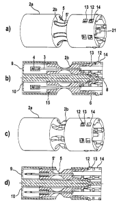
Figure 1 shows a lancet system (1) which is essentially in two parts. Figures
lb and ld
each show a cross-section through the lancet system shown in figure 1 a and 1
c before and
after use respectively. The system has a needle (3), the front tip of which is
wrapped in a
sterile manner with an elastomeric protection (4). Such elastomers which
ensure the
sterility of the needle tip are known for example from the document WO
01/66010 to
which reference is herewith made. The metallic needle (3) is attached to a
plastic body
(2b) and is permanently connected thereto. The plastic body has a rear portion
(6) which
couples the lancet system to a drive plunger such that the needle can be moved
along the
axis (8) in the direction of lancing. The rear
CA 02461109 2004-03-15
- 12-
portion (6) of the plastic body which is a part of the needle body comprises
two arms
which can connect in a form fitting manner during the lancing operation with a
drive
plunger of a lancing aid (not shown) by means of the projecting parts (11). A
form-
fitting connection between a drive plunger and lancet is described for example
in the
document DE 10053974 to which reference is also herewith made. Of course any
other coupling mechanism that is described in the prior art is conceivable for
carrying out the lancing operation. The needle (3) and the plastic body (2b)
that is
permanently connected thereto are movably mounted in the plastic body (2a)
which
represents the protective portion of the needle body. The needle and the
second part
of the needle body (2b) can be moved within this needle body along the
direction of
lancing. The protective portion of the needle body (2a) has a lower wall (10)
which
has a hole (9) through which the needle tip can emerge during the lancing
operation.
The needle body also has an opening (7) at its upper end through which a drive
plunger of a lancing aid can be inserted into the needle body in order to
connect in a
form-fitting manner with the second part of the needle body and perform the
lancing
operation. The protective portion of the needle body (2a) also has two
recesses (13
and ] 4) which allow it to be locked into the second part of the needle body
(2b). In
order to enable the second part of the needle body to engage in the protective
portion, the rear portion (6) of the second part of the needle body also has
locking
lugs (12) which engage in the recesses (14) in a first resting position of the
lancet
system before use and hold the second part of the needle body due to the
spread arms
(6). The middle portion of the protective portion and of the second part of
the needle
body have trough-shaped taper (5 and 5') of the body such that the tapered
parts (5
and 5') exactly fit together in the first resting state before the lancet
system is used
and the lancet system in this position has the design shown in figure 1 a.
In order to carry out the lancing operation, a plunger (not shown) of the
lancing aid
engages through the opening (7) into the lancet system where the plunger
connects in
a form-fitting manner with the arms (6) of the second part of the needle body.
As a
result the arms (6) are pressed together so that the lugs (12) of the arms (6)
no longer
engage in the recesses (14) and the needle can be moved forwards along the
lancing
direction (8). In this process the elastomeric protection (4) is firstly
pressed against
the lower wall (10) of the needle body (2a). If the lancing operation is
continued the
CA 02461109 2004-03-15
- 13-
needle is driven through the elastomeric protection and can thus emerge from
the
opening (9) in the lower wall (10) and produce a wound in the intended part of
the
body. The elastomeric protection (4) is meanwhile held back by the wall (10)
as a
result of which the front part (15) of the second part of the needle body (2b)
corresponding to the recess (16) can move over the elastomeric protection.
After the
lancing operation has been carried out, the needle body (2b) and the needle
are
subsequently retracted into the protective portion (2a) due to the form-
fitting
coupling to the drive plunger. Once the rear arms (6) are in the rear
protective
portion of the needle body (2a), the lugs (12) can engage in the recess (13)
of the
needle body (2a) when the needle body (2b) is pulled back. The lancet system
is now
in a second resting position after the lancing operation. In this position the
second
part of the needle body (2b) protrudes from the opening (5) of the protective
portion
of the needle body (2a) in such a manner that the needle body is deformed in
this
area. The tapered parts (5 and 5') no longer fit together. In a lancing aid
designed in a
corresponding manner which only allows insertion of a lancet system when the
tapered part (5) of the needle body is completely formed according to figure l
a,
insertion of an already used lancet system is blocked according to figure lc.
The example shown in figure 1 has a blocking mechanism and enables the
protective
portion of the needle body to be transferred to a first position during the
lancing
operation. When the lancet system is ejected after the needles have been used,
the
shape of the system has already been changed in such a manner that it is no
longer
possible to reinsert the lancet system in an appropriately designed lancing
aid.
Furthermore the needle tip is completely surrounded by the protective portion
and
hence there is no risk of injury for other persons e.g. during waste disposal.
Figure 2 shows a lancet system in the form of an essentially round lancet
magazine. In
comparison with figure 1 the protective portion of the needle body (2a) is
only
designed as a magazine so that a plurality of needles (3) can be movably
guided
therein.
Figure 2a shows an outer view of a magazine. The magazine housing which forms
the
protective portion of the needle body is designed similarly to figure 1 and
has recesses
(13 and 14) into each of which the locking lugs (12) of the respective second
part of
CA 02461109 2004-03-15
-14-
the needle body (2b) can engage. The lancet system has a magazine axis (21)
that is
arranged concentrically in the protective portion of the needle body and is
used as a
bearing for the lancet system in a lancing aid. The lancet system can be
rotated
around the axis (21) so that one needle in each case can be positioned
relative to a
drive unit (not shown) in the lancing aid. Like the lancet system shown in
figure 1,
the lancet system in figure 2 also has tapered parts (5) within the protective
portion
of the needle body (2a) which are in the form of openings where the openings
are
also essentially tightly closed by the second part of the needle body (2b).
Figure 2b shows a cross-section through the lancet magazine shown in figure
2a. The
system has a similar structure to that of figure 1, but consists of a
plurality of needles
that are equipped with an associated second part of the needle body (2b).
Consequently the lancet system shown in figure 2 has several parts which
include an
outer protective portion of the needle body and several second parts (2b) of
the needle
body. Figures 2c and 2d show the lancet system after use in which all needles
of the
lancet system have already been used for lancing. It is of course also
possible that only
some of the needles have already been used in the lancet system. In this case
the second
part (2b) of the needle body would only protrude through some of the openings
(5) of
the protective portion of the needle body (2a) whereas the other openings
would be
tightly closed by the needle body as shown in figure 2a. Depending on how the
lancet
system interacts with the lancing aid, embodiments are conceivable where
reinsertion
of the lancet system into a lancing aid is already blocked as soon as some of
the needles
have been used or is only blocked after all needles have been completely used
in the
lancet system. Advantageously it is also conceivable that the reinsertion of a
partially
used lancet system into the lancing aid is only possible when the system has
been
positioned relative to the drive plunger in such a manner that only unused
lancets can
be used by the system.
Figure 3 shows a rectangular needle body which also comprises a plurality of
needles
in the form of a magazine. The protective portion of the needle body (2a) also
has
openings (9) in its lower end (10) from which the needles can emerge to
perform a
lancing operation. While in their resting position i.e. when no lancing
operation is
carried out, the needle tips of the needles (not shown) are within the
protective
portion of the needle body (2a) in which the needles can be movably guided.
The
CA 02461109 2004-03-15
-15-
needle body (2a) contains grooves in a lower portion (34) that borders the
lower end
(10) of the needle body which make it easier to grip and thus facilitate its
handling by
the user. Recesses (33) are provided in this portion (34) as holding elements
which, in
an appropriately designed lancing aid, enable the lancet system to lock into
the
lancing aid during insertion. The blocking mechanism (31) is located in the
middle of
the needle body (2a) as part of the needle body (2a) and can be movably guided
to an
upper portion (35) of the needle body (2a), and is firstly held in a starting
position by
spring-mounted arms (39). There is also a recess (32) in the upper part (35)
which
locks the blocking mechanism (31) when the blocking mechanism (31) is guided
along the upper part of the needle body (35).
Figure 3b shows the lancet system after use. As illustrated in figure 3b, the
blocking
mechanism (31) that surrounds the needle body (2a) in the form of a ring is
now
positioned at the upper end of the needle body so that the blocking mechanism
(31)
in this position widens the needle body section (35). Once the blocking
mechanism
(31) has been locked into its position, it is no longer subsequently possible
to reinsert
the lancet system due to the enlarged needle body.
Figures 3c and 3d illustrate in more detail the operation of the blocking
mechanism
(31) which is used in the lancet system described above. In order to lock the
blocking
mechanism (31) in the upper portion (35), the blocking mechanism has locking
arms
(36) which engage in the recesses (32). In the position shown in figures 3b
and c the
locking arms (36) are spring-mounted against the lower edge of the recess (32)
to
secure the blocking mechanism (31) against displacement. The stop (37) also
serves
as an additional counter-flange of the blocking mechanism (31) against the
projection (38) in the upper portion of the needle body component (35). When
the
magazine is inserted as shown in figure 3e for first use in a lancing aid
housing (70),
the rear portion (35) of the magazine housing is positioned in an
appropriately
tapered position (82) of the housing (70). In contrast the front portion (80)
of the
housing (70) is widened so that the widened diameter of the lancet system due
to the
ring that acts as the blocking mechanism can be placed accordingly in the
lancing aid
housing. In this position the lancet system is held in the lancing aid in such
a manner
that a drive unit (not shown) of the lancing aid can engage in the magazine
housing
in order to couple onto a needle of the lancet system. The lancing aid housing
also
CA 02461109 2004-03-15
- 16-
has two stops (83, 84) which are adjacent to the blocking mechanism (31) in
this
position of the lancet system in the lancing aid. If the lancet system is
removed from
the lancing aid housing after use, the stop (84) firstly has the effect that
the blocking
mechanism (31) remains fixed in position in the lancing aid housing while the
magazine housing is pulled out of area (82) of the lancing aid. As a result
the blocking
mechanism (31) is pushed along the needle body to the upper portion (35) of
the
needle body. In this process the blocking mechanism (31) locks with the needle
body
and the projection (38) and the stop (37) block further movement of the
blocking
mechanism along the needle body. If the blocking mechanism (31) rests against
the
projection (38), a further pulling movement on the magazine housing overcomes
the
resistance of the stop (84) and the magazine can be removed from the lancing
aid.
The magazine is now outside the housing in a used state as shown in figure 3b
where
the blocking mechanism (31) is permanently positioned on the needle body due
to
the locking hooks (36) and the stop (37). If the lancet magazine is reinserted
into the
lancing aid housing, the magazine can no longer be pushed into the tapered
area (82)
of the lancing aid due to the widened circumference of the upper section (35)
of the
needle body. Hence it is no longer possible to position the lancet system in
its original
position in the lancing aid. The lancet system can no longer be held in the
lancing aid.
The coupling of individual needles to the drive unit of the lancing aid in
order to
carry out a lancing operation is blocked. Moreover after the lancet system has
been
ejected, the user can easily visually recognize that the lancet system is a
used system
due to the displaced ring. For this purpose it is also conceivable that the
blocking
mechanism (31) is highlighted in colour.
As an alternative to the described change in the needle body (2a), it is for
example
also conceivable that the blocking mechanism (31) can be moved over the
recesses
(33) of the lancet system. In this case a reinsertion of the lancet system in
a lancing
aid would be prevented because the lancet system could no longer lock into the
lancing aid. Other embodiments using a movably mounted blocking mechanism are
conceivable which for example result in a reduction in the size of the upper
section
(35) of the needle body. In this case an unused lancet system e.g. in the
state shown in
figure 3b, is firstly placed in a lancing aid. A used lancet system would then
be
characterized in that the blocking mechanism (31) would have been pushed over
the
CA 02461109 2004-03-15
- 17-
needle body portion (35) in such a manner that the upper section (35) of the
needle
body (2a) is diminished in size. Figure 3a would thus represent the ejected
state of the
system. A correspondingly designed lancing aid would then for example have
holding
elements that could no longer interact with a lancet system that has been
changed in
this manner and reinsertion into the lancet system would no longer be
possible. The
locking elements of the blocking mechanism and of the needle body (2a) would
then
have to be adapted accordingly. Furthermore it is also conceivable that a
movable
blocking mechanism (31) ensures that a reinsertion of the lancet system is
blocked
and also protects the needle tips. In this case the needle tips would not, as
shown in
figure 3, be retracted into a protective portion of the needle body after the
lancing
operation. Hence the needle tips would not be automatically protected in a
resting
position. For example protection from the needle tips would not be ensured
until the
lancet system has been ejected from the lancing aid. According to the blocking
mechanism shown in figure 3a, a movement of the blocking mechanism (31)
elongates the needle body in the area of the needle tips so that the needle
tips are
surrounded in a protective manner by the blocking mechanism and at the same
time
the blocking mechanism is activated due to a change in the shape of the body.
In this
case a part of the needle body acts as a blocking mechanism and also as a
protective
portion of the needle body which surrounds the needle tip area when the lancet
system is ejected. 'Che protective portion of the needle body and the blocking
mechanism then comprise one structural element of the needle body.
Figure 4 shows a rectangular lancet system in which several needles are
positioned in
chambers (42) of the protective portion of the needle body (2a). The upper
section of
the protective portion of the needle body has a blocking mechanism (41) in the
form
of a button which is located above the protective portion of the needle body
and can
be moved along direction (45) towards the protective portion of the needle
body. The
upper part of the button has a guide groove (49) which engages in a matching
lip of
the lancing aid (not shown) so that the lancet system can be securely
positioned in
the lancing aid. Once positioned in this manner, a drive plunger of the
lancing aid
(not shown) can couple with the rear area (48) of the needle (3) to carry out
a lancing
operation. For this purpose the needle is moved along direction (43) relative
to the
protective portion of the needle body and the needle tip emerges from the
protective
CA 02461109 2004-03-15
- 18-
portion (2a) of the needle body. As in the systems that have already been
described,
the needles are returned to the magazine after the lancing operation and the
needle
tip is retracted within the needle body (2a). The magazine is moved to the
next
position by moving the drive plunger of the lancing unit along direction (44)
until
the plunger can couple with a needle positioned in the adjacent chamber (42)
in
order to carry out a new lancing operation. If the lancet system has to be
replaced in
the lancing aid, the drive plunger must firstly be moved outside the rear area
(46) of
the needle body (2a). For this purpose the magazine is moved to the next
position
and at the same time the button (41) is pressed down by a ramp on the housing
of the
lancing aid. The button (41) is now shifted within the lancet system as shown
in
figures 4c and d so that the section (50) of the button protrudes from the
bottom of
the needle body (2a). In this position a recess (47) of the button (41)
engages the rear
area (48) of the needle (3) which prevents the lancing aid from coupling again
with
the lancet system as shown in the front view of figure 4d. Hence a lancing
operation
cannot be carried out with a lancet system of figure 4c or d. Moreover the
lancet
system cannot be reinserted into the lancing aid due to the change in the
shape of the
needle body in area (50). Hence the lancet system cannot be positioned via the
guide
groove (49) as part of a holding element.
Figure 5 shows a round-shaped lancet system which also contains several
needles
within the needle body. Similarly to figure 2, the lancet system has a
multipart needle
body. A channel (52) is arranged along the axis of rotation of the lancet
system and a
plug (53) is located in this channel at the upper end of the lancet system.
The plug
(53) is held in its first position by expanding holding arms (56) and this
position
represents the unused state of the lancet system. The holding arms (56) engage
in a
taper of the plug (53) which is formed by planes (55) of the plug which slant
towards
one another. When the lancet system is inserted into a lancing aid (70) the
plug (53)
is pressed within the channel (52) towards the needle tips by means of a
centering
plunger (57) of the lancing aid. The holding arms (56) are spread when the
plunger is
pressed in due to the slanting planes (55) of the plug (53). When the holding
arrns
(56) of the lancet system are spread the plunger (57) can engage between them.
Hence the plunger (57) can be almost completely inserted into the lancet
system and
is used as a bearing for and to position the magazine. An appropriately
designed drive
CA 02461109 2004-03-15
- 19-
unit of the lancing aid can thus be oriented relative to the lancets of the
system such
that it can be coupled to a lancet and a lancing operation can be carried out.
After the
magazine has been used it is removed from the lancing aid. For this purpose
the
plunger (57) is pulled out from the interior of the magazine housing while the
plug
(53) remains at the lower end of the magazine in the area of the needle tips.
Consequently a used lancet system is designed as shown in figure 5c in which
the plug
(53) is no longer held in the upper section of the holding arms (56). If an
attempt is
made to insert the used lancet system into the lancing aid, the plunger (57)
strikes the
upper portion (56) of the holding arms which in their unspread state prevent
the
plunger from penetrating into the lancet system. The absence of the plug (53)
prevents the plunger (57) of the lancing aid from spreading the holding arms
and
thus the lancet system cannot be placed in the lancing aid.
Figure 6 shows another embodiment of a lancet system that is arranged within a
lancing aid. Figure 6a to d firstly show a lancet system that is similar to
that of figure
1. Like figure 1 the system shown in figure 6 also has an elastomer (4) which
surrounds the needle tip in a sterile manner and a two-part needle body which
has a
taper (5, 5') in its middle. The second part of the needle body (2b) whose
movement
is guided in the interior of the protective portion of the needle body (2a)
also has
arms (6) in its rear section which can couple in a form-fitting manner with a
plunger
(78) of the lancing aid (72). As shown in figure 6b and c, the plunger (78)
engages
with a head (71) in the second part (2b) of the needle body and moves the
needle
along the axis (8) in the direction of lancing. In this process the arms (6)
of the needle
body (2b) are pressed together and the projections (11) engage behind the
notches in
the head (71). The mode of operation of the lancet system is similar to that
already
described in figure 1 and is thus only shown again here with regard to its
interaction
with the lancing aid. The lancing aid (72) has a locking lever (74) that is
mounted in
the lancing aid and is rotatably pivoted on an axis (75). The locking lever
(74) has a
circular shape in a first area (77) such that the locking lever can engage in
a form-
fitting manner in the taper (5) of the lancet system.
Figure 6a shows the state of the lancing aid with the lancet system before use
in the
inserted state. If it is intended to use the lancing aid for a lancing
operation, the
CA 02461109 2004-03-15
-20-
locking lever (74) is rotated by about 90 either automatically when a lancing
operation is triggered or separately by the user, such that the lower section
(77) of the
locking lever no longer engages in the taper (5, 5'). The rotation of the
locking lever is
ensured by the fact that the lancing aid also has a depression (76) in the
housing of
the lancing aid which allows the locking lever to rotate around the axis of
rotation
(75). When the lancing operation is carried out, the second part of the needle
body
(2b) can move along the protective portion of the needle body (2a) and a
section of
the needle body (2b) emerges from the opening of the needle body (2a) without
being hindered by the locking lever (74). In this process the needle tip is
driven
through the elastomer and the exit opening (9) of the lancet system and
through an
exit opening (73) of the lancing aid.
After the lancing operation the needle returns to its resting position during
which,
however, the second part of the needle body locks into the recess (13) of the
protective portion of the needle body. As already described in figure 1, this
results in
a change in the outer shape of the needle body in the area of the taper (5)
since the
second part of the needle body (2b) now protrudes from the opening of the
needle
body (2a). After the lancet system has been removed from the lancing aid, the
locking
lever (74) rotates back into its initial position as shown in figure 6a. As
indicated in
figure 6d, a reinsertion of the lancet system into the lancing aid is blocked
by the
locking lever (74). The locking lever (74) can no longer engage in the taper
(5) of the
used lancet system since the taper (5) is partially closed by the second part
of the
needle body (2b). Hence the lancet system can no longer be positioned and thus
held
in its original position. The plunger (78) can no longer engage in the lancet
system.
The head (71) and the projections (11) are prevented from forming a form-
fitting
connection.
Figures 6e - h show embodiments similar to figures 6a - d in which the lancet
system
consists of a plurality of needles so that they can be stored in a magazine as
shown in
figure 2. The operating principles are, as already described, identical and
can be simply
transferred from the system with one needle to the system shown in figures 6e -
h. At
this point the intention is only to illustrate an embodiment that allows a
magazine to
be reinserted whose needles have only been partially used. For this the user
must rotate
CA 02461109 2004-03-15
-21-
the magazine relative to the lancing aid housing until the locking lever (74)
can engage
in a taper (5) which is not blocked by a needle body (2b). This positioning of
the lancet
system relative to the lancing aid and consequently relative to the drive
plunger ensures
that only a lancet that has not yet been used is employed for the next lancing
operation.
An advance of the lancet system in only one direction of rotation and a
mechanism
that allows no more than one rotation of the lancet system by 3600 can be
added as
required in order to prevent already used lancing aids from being used again.
Figure 7 shows another embodiment of a lancet system that is in the form of a
round
magazine housing. The needle body design has several parts similar to the
figures that
have already been described. The sterile protection and needles are also
arranged as
already described and thus a more detailed description is omitted here.
Similar to the
system described in figure 5 the blocking mechanism shown in figure 7 is also
actuated when the lancet system is inserted into the lancing aid. For this
purpose the
needle body (2a) has a blocking mechanism (31) that is in the form of an outer
ring
that surrounds the upper section (35) of the needle body. When positioned at
this
position the blocking mechanism (31) essentially covers the elastic arms (90)
that are
located in the upper portion of the needle body (35). As a result the elastic
arms (90)
are pressed into the recess (95) of the needle body (2a). The blocking
mechanism
(31) also has a circular protrusion at its lower end that enlarges the
circumference of
the needle body (2a) at this position. If the lancet system is inserted into a
lancing aid,
the circumference of the lancing aid is selected such that the ring (96)
cannot be
inserted into the lancet system. The ring is pressed downwards relative to the
needle
body into the area of the lancet tips when the lancet system is inserted into
the
lancing aid by means of a lower edge (97) acting as a counter-flange for the
lancing
aid housing. As a result the spring-mounted locking arms (90) are released
from the
ring. The resting arms are now in a spread state in the lancing aid and are
pressed
against the inner housing wall (98) of the lancing aid. When a used lancet
systern is
removed from the lancing aid, the locking arms (90) slide along the sloping
housing
wall (98) in a tapered area of the lancing aid housing and are firstly pressed
into the
recess (95) of the needle body due to the slanting wall (98). Hence the lancet
system
can be readily removed from the tapered area of the lancing aid. The used
lancet
system is subsequently present in a changed form as shown in figure 7c. When
the
CA 02461109 2004-03-15
-22-
system is reinserted into a lancing aid the locking arms (90) are now spread
and thus
the circumference of the needle body (2a) is enlarged in the area (35) thus
preventing
an insertion of the lancet system into the front narrowed area of the lancing
aid.