Note: Descriptions are shown in the official language in which they were submitted.
CA 02464276 2004-04-13
Case 2650 Patent Application
DESCRIPTION
HANDLE AND LATCH FOR A REMOVABLE DIRT SEPARATION
SYSTEM
Technical Field
Generally, this invention relates to vacuum cleaners. In particular,
the invention relates to a handle and latch for a removable dirt separation
system for a vacuum cleaner. Moreover, the invention relates to a handle and
latch for removable dirt separation system for use in a bagless vacuum
cleaner.
BACKGROUND OF THE INVENTION
Upright vacuum cleaners are well known in the art. Typically, these
vacuum cleaners include an upper housing pivotally mounted to a vacuum
cleaner foot. The foot is formed with a nozzle opening defined in an
underside thereof and may include an agitator mounted therein for loosening
dirt and debris from a floor surface. A motor and fan may be rnounted to
either the foot or the housing for producing suction at the nozzle opening.
The suction at the nozzle opening picks up the loosened dirt and debris and
produces a fiow of dirt-laden air which is ducted to the vacuum cleaner
housing.
In conventional vacuum cleaners, the dirt laden air is ducted into a
filter bag supported on or within the vacuum clleaner housing. Atternatively,
bagiess vacuum cleaners duct the flow of dirt-laden air into a dirt separation
system having a dirt cup which filters the dirt particles from the airflow
before
exhausting the filtered airflow into the atmosphere. Various dirt separation
systems have been used on bagiess vacuum cleaners to separate the dirt
particles from the airflow.
1
CA 02464276 2004-04-13
Typically, a bagiess vacuum needs a latch to secure the bagiess
dirt separation system to the vacuum cleaner. In addition, it is also
desirable
to provide a carry handle which allows the operator to easily move the dirt to
a
dirt collecting receptacle. Some bagless vacuum cleaners provide a latching
mechanism integrated within the housing combined with a separate carry
handle integrated within the dirt cup. Typically, these separate latch and
hand systems are complex and add cost to the vacuum cleaners. Other
systems have an integrated latch and carry handle on the lid of the dirt cup.
Such systems have the disadvantage of not allowing the operator to
manipulate the dirt cup with the carry handle when the lid is removed from the
dirt cup.
What is needed therefore, is a handle and latch systems that
overcomes the above-mentioned drawbacks.
SUMMARY OF THE INVENTION
In accordance with a first aspect of the present invention, there is
provided an upright vacuum cleaner. The upright vacuum cleaner includes a
carpet engaging nozzle base and an upper housing pivotally attached to the
nozzle base. The upright vacuum cleaner further includes a removable
bucket releasably secured to the upper housing and a bucket handle rotatably
attached to the bucket and movable between a first position and a second
position. The upright vacuum cleaner yet further includes a latch adapted to
secure the bucket to the upper housing when the handle is in the first
position
and release the bucket from the upper portion when the handle is in a second
position. The bucket may be removed from the upper housing when the latch
is released from the upper housing. The bucket is re-secured to the upper
housing by returning the bucket handle to the first position.
In accordance with a second aspect of the present invention, there
is provided an upright vacuum cleaner. The upright vacuum cleaner includes
a carpet engaging nozzle base and an upper housing pivotally attached to the
nozzle base. The upright vacuum cleaner further includes a removable
2
CA 02464276 2006-11-01
61935-199
bucket releasably secured to the upper portion and a bucket
handle rotatably mounted to the bucket and forming a loop
above a portion of the bucket when the handle is in a carry
position. The upright vacuum cleaner still further includes
a filter assembly positioned relative to a dirt separation
chamber at least partially formed by the bucket when the
bucket is placed in an operational position relative to the
upper housing. The bucket may be emptied by rotating the
bucket from a carry position to an empty position.
In accordance with a third aspect of the present
invention, there is provided a method of operating a vacuum
cleaner. The vacuum cleaner includes a housing, a bucket,
and bucket handle rotatably mounted to the bucket. The
method includes the step of rotating the bucket handle in a
first direction to secure the bucket to the housing and
place the cleaner in an operation position. The method
further includes the step of rotating the bucket handle in a
second direction to release the bucket from the housing.
The method still further includes the step of removing the
bucket from the housing and placing the handle in a carry
position and emptying the bucket by rotating the bucket from
a carry position to an empty position
In accordance with another aspect of the
invention, there is provided an upright vacuum cleaner,
comprising: a carpet engaging nozzle base; an upper housing
pivotally attached to the nozzle base; a removable bucket
releasably secured to the upper housing; a bucket handle
rotatably attached to the bucket and movable between a first
position and a second position, wherein the bucket handle is
substantially flush to a surface of the upper housing when
the handle is in the first position; and a latch adapted to
secure the bucket to the upper housing when the handle is in
the first position and release the bucket from the upper
3
CA 02464276 2006-11-01
61935-199
housing when the handle is in the second position, wherein:
the bucket may be removed from the upper housing when the
latch is released from the upper housing, and the bucket is
re-secured to the upper housing by returning the bucket
handle to the first position.
In accordance with yet another aspect of the
invention, there is provided a method of operating a vacuum
cleaner having a housing, a bucket, and a bucket handle
rotatably mounted to the bucket, comprising the steps of:
rotating the bucket handle in a first direction to secure
the bucket to the housing and place the vacuum cleaner in an
operation position; rotating the bucket handle in a second
direction to release the bucket from the housing; removing
the bucket from the housing and placing the handle in a
carry position; and emptying the bucket by rotating the
bucket from a carry position to an empty position.
BRIEF DESCRIPTION OF DRAWINGS
Fig. 1 is a perspective view of an upright vacuum
cleaner which incorporates the features of the present
invention therein;
Fig. 2 is a perspective view similar to Fig. 1,
but showing a dirt separation system removed from the vacuum
cleaner;
Fig. 3 is a perspective view of the dirt
separation system of Fig. 2 with a filter assembly removed;
Fig. 4 is an exploded perspective view of the
filter assembly of the dirt separation system of Fig. 3;
Fig. 5 is a cross-sectional view of the dirt
separation system of Fig. 2, taken along the line 5-5;
3a
CA 02464276 2006-11-01
61935-199
Fig. 6 is a side view of an upper portion of the
vacuum cleaner
3b
CA 02464276 2004-04-13
shown in Fig. 1, showing a bucket handle in a first position;
Fig. 6A is an enlarged cutaway view of a portion of the vacuum
cleaner of Fig. 6;
Fig. 7 is a view similar to Fig. 6, but showing the bucket handle in a
second position;
Tig. 7A is an enlarged cutaway view of a portion of the vacuum
cleaner of Fig. 7;
Fig. 8 is a side view of the removable dirt separation system of Fig.
2 in a carry position;
Fig. 9 is a view similar to Fig. 8, but showing the filter assembly
removed and a dirt cup in an empty position;
Fig. 10 is a cross-sectional view of the upper housing of the
vacuum cleaner of Fig. 6, taken along the line 10-10 showing the air flow
within the upper housing;
Fig. 11 is a cross sectional view of the upper housing and dirt cup
of the vacuum cleaner of Fig 6, taken along the line 11-11 showing the air
flow
around the dirt cup;
Fig. 12 is a front view of the upper housing of the vacuum cleaner
of Fig 2, as viewed along the line 12-12 showing the air flow around the
exterior of the upper housing;
Fig. 12A is an enlarged view of a portion of upper housing shown in
Fig. 12;
Fig. 13 is a partial cut away perspective view of an upper portion of
the vacuum cleaner showing the handle locking mechanism;
Fig. 14 is a partial cross sectional view of the upper housing of Fig.
13, taken along the line 14-14 and showing the latch in a latched position;
Fig. 15 is a view similar to Fig. 1:3, but showing the latch in a
release position;
Fig. 16A is a view similar to Fig. 14, but showing the latch in a
release position and the handle in an operational position;
Fig. 16B is a view similar to Fig. 16A, but showing the handle in a
storage position;
4
CA 02464276 2004-04-13
Fig. 17 is a perspective view of the base of the vacuum cleaner
shown in Fig. 1;
Fig. 18 is a cross sectional view of the base of the vacuum cleaner
of Fig 17, taken along the line 18-18 showirig the blocker door in a closed
position; and
Fig. 19 is a cross sectional view sirnilar to Fig. 18 but showing the
blocker door in an open position.
DETAILED DESCRIPTION
While the invention is susceptible to various modifications and
alternative forms, a specific embodiment thereof has been shown by way of
example in the drawings and will herein be described in detail. It should be
understood, however, that there is no intent to limit the invention to the
particular form disclosed, but on the contrary, the intention is to cover all
modifications, equivalents, and alternatives falling within the spirit and
scope
of the invention as defined by the appended claims.
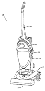
Referring now to Fig. 1, there is shown an upright vacuum cleaner
which incorporates the features of the present invention therein. The
vacuum cleaner 10 includes a vacuum cleaner base 12 and a vacuum cleaner
upper housing 20 pivotally connected to the base 12. The base 12 is adapted
to engage a carpeted floor surface. The base 12 includes a nozzle opening
14 formed in an underside thereof for suctioning of dirt particles from a
carpeted floor surface. In addition, an agitator 154 (see Fig. 1 8) is
positioned
within the nozzle opening 14 to assist in removing dirt particles from the
carpeted floor surface.
Referring now to Fig. 2, there is shown the vacuum cleaner of Fig.
1, with a dirt separation system 30 removed from the upper housing 20. The
upper housing 20 includes an inlet interface 22 in fluid communication with
the nozzle opening 14. The upper housing 20 further includes -an outlet
interface 24 for exhausting filtered air from the removable dirt separation
5
CA 02464276 2004-04-13
system 30. A motor-fan unit 26 (See Fig. 10) is positioned in a lower portion
of the upper housing 20 and is adapted to generate an airflow from the nozzle
opening 14 to the outlet interface 24. In this type of vacuum cleaner, the
motor-fan unit 26 is positioned downstream from the outlet interface 24 such
that the low pressure at a fan inlet 127 creates an airflow that draws low
pressure air from the nozzle opening 14 to the outlet interface 24 via the
inlet
interface 22 and dirt separation system 30. The air which reaches the motor-
fan unit 26 has been filtered by the dirt separation system 30 prior to
reaching
the motor / fan unit 26, hence these vacuums are generally referred to as
"clean air" units. The air which exits the motor-fan unit 26 is then exhausted
from the vacuum cleaner 10.
In another type of vacuum cleaner, the motor-fan unit 26 is
positioned between the nozzle opening 14 and the inlet interface 22 such that
the low pressure at the fan inlet creates a suction in the nozzle opening 14.
This suction draws the loosened dirt from the floor surface into nozzle
opening
14 and creates a flow of dirt-laden air which travels through the motor-fan
unit
26. The flow of dirt-laden air is blown upwardly through the inlet interface
22
through the dirt separation system 30, through the outlet interface 24 and
exhausted from the vacuum cleaner 10. The air which reaches the motor-fan
unit 26 has not been filtered either by the dirt separation system 30 or a bag
prior to reaching the motor/fan unit 26, hence these vacuum cleaners are
generally referred to as "dirty air" units. It should be appreciated that the
inventions described herein may be used in either a dirty air unit or a clean
air
unit without deviating from the scope of the invention.
Referring now to Fig. 3, there is shown an exploded view of the dirt
separation system 30 with a filter assembly 40 removed to show the interior of
a bucket, or dirt cup 50. The dirt cup or bucket 50 has a distinctive bucket
handle 52 rotatably attached thereto. The dirt cup 50 also includes a number
of sidewalls 54 which define the exterior of the dirt cup 50. The bucket
handle
52 is movable between a generally vertical first position, shown in Fig. 1, a
generally vertical carry position, shown in Fig. 2, an emptying position shown
in Fig. 9, and a generally horizontal second position, shown in Fig. 3. The
6
CA 02464276 2004-04-13
filter assembly 40 includes a lid member 41 liaving an exit opening 42 defined
therethrough. A compressible seal 46 around the periphery of the exit
opening 42 is adapted to seal against the exit interface 24 (See Fig. 2) of
the
upper housing 20. The lid member 41 further includes a sealing arrangement
44 around the periphery of the lid member 41. The sealing arrangement 44 is
bonded to the lid member 41 and is adapted to engage and seal against one
or more of the side walls 54 of the dirt cup 50 to prevent dirt laden
particles
from bypassing the exit opening.
Referring now to Fig. 4, there is shown an exploded view of the
filter assembly 40. The filter assembly 40 further includes a removable filter
60. The removable filter 60 includes a base plate 64, a sealing plate 62 with
a
filter exit 66 (See Fig. 5) defined therethrough, and a vertically extending
filter
element 68. The filter element 68 includes a first inner layer formed of a
melt-
blown polypropylene, a second middle layer formed of a spun-bond polyester
and an outer third layer formed of an expanded polytetrafluoro-ethylene
(ePTFE) membrane. The ePTFE outer layer provides non-stick properties to
the filter element 68 and allows any dirt or dust accumulated on the filter
element 68 to be easily displaced therefrom. Although the filter element 68 is
shown and described as having three layers, it is understood that the filter
material may include any number of layers or be formed of any number of
materials such as a micro-glass or a melt-blowri polyester without affecting
the
concept of the invention.
The filter exit 66 is adapted to seal to an extension 48 of the lid
member 41 to place the exit opening 42 of the lid 41 in fluid communication
with the filter exit 66. A upper edge of the filter element 68 is bonded to
the
sealing plate 62 and a lower edge of the filter element 68 is bonded to the
base plate 64. The base plate 64 and sealing plate 62 form a generally oval
shape around the exit opening 42 of the lid member 41. This oval shape
provides a significant amount of filter material to be placed within small
volume.
The filter member 68 is pleated around the oval track formed by
the base plate 64 and sealing plate 62 to further increase the effective
filter
7
CA 02464276 2004-04-13
area of the filter member 68. It should be appreciated that once the
removable filter 68 is assembled to the lid rnember 41 and the lid member 42
is placed in the dirt cup 50, the airflow from the dirt cup 50 may only exit
through the exit opening 42 via the filter element 68, as the sealing
arrangement 44 prevents air flow from by-passing the filter element 68
The filter assembly 40 further includes a screen support 70 which
surrounds the removable filter 60. The screen support 70 includes a number
of horizontal openings 74 defined therethrough which place the interior of the
screen support 70 in fluid communication with the exterior of the screen
support 70. In addition, a screen element 76 covers each of the screen
openings 74. The screen elements 76 may be formed of a number of
different materials such as metal or synthetic rriesh or screens, cloth, foam,
a
high-density polyethylene material, apertured molded plastic or metal, or any
other woven, non-woven, natural or synthetic coarse filtration materials
without affecting the scope of the invention. It should be appreciated that
the
screen element 76 separate dirt particles frorn an air stream prior to those
particles reaching the filter element 68 of the filter 60.
The screen support 70 further inclucies a catch 78 defined thereon
which is adapted to be engaged by a latch 49 of the lid member 41. The
screen support 70 is attached to the lid mernber 41 when the latch 49
engages the catch 78. Alternatively, the screen support 70 may be removed
from the lid member 41 when the latch 49 is disengaged from the catch 78.
Referring now to Fig. 5, there is shown a cross sectional view of
the dirt separation system 30. When the dirt cup separation system 30 is
secured to the upper housing 20, as shown in Fig. 1, the vacuum cleaner is
placed in an operational mode. As shown, the dirt cup 50 further includes a
bottom wall 55 having an inlet 56 defined therethrough. The inlet 56 seals
against the inlet interface 22 of the upper housing 20 to place the dirt cup
50
in fluid communication with the agitator chamber 14. The dirt cup 50 further
includes a conduit 57 which directs a dirt laden air stream from the inlet 56
to
a flow directing nozzle 58, as indicated by arrovv 80. The flow-directing
nozzle
58 creates a sheet-like airflow, indicated by arrow 81, which is generally
8
CA 02464276 2004-04-13
parallel to the screen elements 76 of the filter assembly 40. It should be
appreciated that the air flow created by the flow directing nozzle 58 prevents
dirt particles from accumulating on the screen elements 76 of the filter
assembly 40. From the flow-directing nozzle: 58, the air stream generally
settles in an expansion chamber 59 wherein inertial and gravitational forces
separate large particles from the air stream, as the air stream is generally
directed as indicated by arrows 82.
The air stream exits the expansion chamber 59 via the screen
elements 76. The screen elements 76 act as a primary separation means to
separate coarse particles from the air stream vuhich exits the expansion
chamber 59. The air stream then generally passes (i) vertically through the
screen elements 76, (ii) horizontally outwardly through a gap created between
the screen elements 76 and the base plate 64 by tabs 78, vertically along an
exterior of the filter 60, and horizontally toward the filter element 68, as
generally indicated by the arrows 83. The filter element 68 act as a
secondary separation means to separate fine particles from the air stream
which exits the expansion chamber 59. The filter assembly 40 has the
advantage of horizontal screen elements 76 which are cleaned by the nozzle
58 combined with the vertical filter element 68 which provides a relatively
large filter area. The filtered air stream then exits the dirt separations
system
30 via the exit opening 42 in the general direction of arrows 84. It should be
appreciated that the exit opening 42 seals against the exit interface 24 (see.
Fig. 2) of the housing when the dirt separation system 30 is secured to the
upper housing (as shown in Fig. 1).
Referring now to Figs. 6 and 6A, there is shown a side view of the
upper housing 20 showing the bucket handle 52 in the first position. In the
first position, the handle 52 is substantially vertical. Furthermore, the
bucket
handle 52 is substantially flush with a surface 13 of the upper housing 20.
The bucket handle 52 is rotatably mounted to the dirt cup or bucket 50 about
a hub 53 such that the bucket handle 52 may rotate relative to the bucket 52
about the hub 53 in the general direction of arrows 99 and 100. Fig. 6A
shows an enlarged portion of a latch portion 90 of the bucket handle 52. The
9
CA 02464276 2004-04-13
latch portion 90 engages a catch 15 defined in the upper housing 20 as the
bucket handle 52 is rotated in the general direction of arrow 100. In
particular,
an extension 92 of the latch portion 90 engages a detent defined in the catch
15. Thus, the latch portion 90 of the bucket handle 52 secures the bucket or
dirt cup 50 to the upper housing 20 when the bucket handle 52 is positioned
in the first position. When the bucket or dirt cup 52 is secured to the upper
housing 20, the vacuum cleaner is placed in ari operational mode whereby an
air stream may be advanced from the nozzle 14 to the dirt separation system
30 where particles are separated from the air stream by the filter assembly
40.
Referring now to Figs. 7 and 7A, there is shown the bucket handle
52 in second position. In the second position, the handle 52 is moved toward
a horizontal plane from the first position showri in Fig. 6. Figure 7A shows
an
enlarged partially cut-away of the latch portion 90 of the upper handle 52 in
the second position. The latch portion 90 releases the catch 15 defined in
the upper housing 20 as the bucket handle 52 is rotated in the general
direction of arrow 99. In particular, an extension 92 of the latch portion 90
disengages the detent defined in the catch 15. Thus, the latch portion 90 of
the bucket handle 52 releases the bucket or dii-t cup 50 from the upper
portion
20 when the handle 52 is positioned in the second position.
Referring now to Fig. 8, there is shown the dirt separation system
30 in a carry position. Once the dirt cup or bucket 52 is released from the
upper housing 20, as described above, an operator may grasp the bucket
handle 52 and carry the dirt separation system 30 to a dirt receptacle (not
shown).
Referring now to Fig. 9, there is shown the dirt separation system
30 in an emptying position. To move the dirt separation system 30 from the
carry position to the emptying position, the filter assembly 40 is removed
from
the dirt cup 50, and the dirt cup 50 is rotated in the general direction of
arrow
99 relative to the handle 52 to allow the contents of the dirt cup 50 to be
emptied in the dirt receptacle. The filter assenibly 40 may be further cleaned
by detaching the screen support 70 and the filter 60 from the lid member 41,
as shown in Fig. 4. Once detached, the screen elements 76 and filter
CA 02464276 2004-04-13
element 68 may be cleaned by the operator. The filter assembly 40 may be
reassembled and repositioned within the dirt cup or bucket 50 an.d the dirt
separation system 30 returned to the carry position (shown in Fig. 8). Once in
the carry position, the dirt cup 50 may be moved from the dirt receptacle to
the vacuum cleaner 10. The dirt separation system 30 may then be
repositioned in the upper housing 20 as shown in Fig. 7. The dirt cup or
bucket 50 may then be secured to the upper housing 20 by moving the bucket
handle 52 from the second position of Fig. 7 to the first position of Fig. 6,
as
described above. Securing the dirt cup to the upper housing places the
vacuum cleaner in an operational mode.
Referring now to Fig. 10, there is shown a cut-away view of the
internal airflow path within the upper housing 20, as taken along the line 10-
10
of Fig. 6. Airflow from the nozzle 14 is directed to the inlet interface 22
via a
hose 170, shown in Figs. 18 and 19. From the inlet interface 22, dirt enters
the dirt separation system 30 via the inlet 56 and exits the dirt separation
system 30 via the exit opening 42 as described above in connection with Fig.
above. The exit opening 42 is sealed agairist the exit interface 24. From
the exit interface 24, filtered air is directed to an inlet 27 of the motor-
fan unit
26 via a fan duct 110. The fan duct 110 within the housing 20 extends
substantially the entire length of the dirt cup 50 as the exit interface 24 is
positioned above of the dirt cup 50. It should be appreciated that the length
of
the fan duct 110 muffles noises created by the motor-fan unit 26. After
exiting
the motor fan unit 26 via the exit 28, the air flow is directed upwardly by a
fan
exhaust duct 112. The fan exhaust duct 112 directs the air flow to a final
filter
116 comprising a filter element 117 and a filter retainer 118 (shown in Fig.
2).
The fan exhaust duct 112 also extends substantially the entire length of the
dirt cup 50. It should further be appreciated that the length of the fan
exhaust
duct 112 helps muffle noises created by the motor-fan unit 26.
Referring now to Fig. 11, there is shown a cross sectional view of a
portion of the upper housing 20 with the dirt cuip 50 placed in the
operational
mode. The airflow which passes through the filter 116 exits the upper housing
20 into an expansion chamber 120 and travels generally laterally in the
11
CA 02464276 2004-04-13
vacuum cleaner 10 in the general direction of arrows 101. The expansion
chamber 120 is an expanding area defined between a portion of the upper
housing 20 and a number of side walls 54 of the dirt cup 50 which allows the
airflow to diffuse prior to exiting the vacuum cleaner 10. The expansion
chamber 120 provides a significant reduction in the sound created by the
motor/fan unit 26. The dirt cup 50 further includes a number of lateral
extensions 55 which cooperate with surfaces 114 of the upper housing 20 to
define an expansion chamber exit 122. After passing through the expansion
chamber 120, the muffled air flow is allowed to exit the vacuum cleaner 10
along the length of the expansion chamber exit 122, in the generai direction
arrow 102, at a reduced velocity and sourid level. The length of the
expansion chamber exit 122 can best be seen in Fig. 1.
Referring now to Figs. 12 and 12A, there is shown the air flow
within the expansion chamber 120 having the dirt separation system 30
removed for clarity of description. In particular, it can be seen that the
airflow
indicated by the arrows 101 and 102 is vertically distributed along the height
of the expansion chamber 120. In addition, it should be noted that a number
of vanes 124 are attached to the upper housing 20. These vanes 124 direct
the airflow away from the base 12. As the upwardly directed airflow passes
through the expansion chamber exit 122, it does not disturb the surface being
cleaned by the vacuum cleaner 10. In addition, it should be appreciated that
the vanes 124 could alternately be placed on the lateral extensions 55 of the
dirt cup 50 to direct the airfiow away from the base 12.
Referring now to Figure 13, there is shown a handle 130 positioned
in an operational position. The handle 130 is rotatably mounted to the upper
housing 20. The handle 130 rotates about a round axle extension 132
attached to a lower portion of the handle 130. This arrangement allows the
handle 130 to rotate about the axel extension 132 in the direction of arrows
99
and 100. A latch 140 is provided to secure the handle 130 in the operational
position. The latch 140 rotates about an axel '142 in the general direction of
arrows 99 and 100. The axis of rotation of the latch 140 about the axel 142 is
offset from the axis of rotation of the handle 130 about the axle extension
132
12
CA 02464276 2004-04-13
such that the latch 140 may engage exterior portions of the handle 130. A
spring 143 interposed between the housing 20 and the latch 140 biases the
latch 140 in the general direction of arrow 99. A lever 144 is secured to the
axel 142. An extension of the lever 144 is the actuator 145 which extends
through the housing 20 and allows and operator to rotate the latch 140 in the
general direction of arrow 100 by depressing the actuator 145. The textured
surface 146 of the actuator assists the operator in moving the actuator 145.
Referring now to Fig. 14, there is shown a partial schematic view of
the engagement of the latch 140 with the handle 130. In particular, as the
spring 143 biases the latch 140 in the general direction of arrow 99, the
latch
140 engages a notched engagement surface '134 of the handle 130. Biasing
the latch 140 against the engagement surface 134 places the latch 140 in the
locked position which holds the handle 130 in an operational position. It
should be appreciated that the latch 140 engages the handle 130 over
substantially the entire width of the handle 130 to provide a substantial
latching force between the handle 130 and the latch 140.
Referring now to Fig. 15, there is shown the latch 140 in the
release position, which allows the handle 130 to be placed in a storage
position. To place the latch in the release position, the operator moves the
actuator 145 in the general direction of arrow '100 by overcoming the biasing
force of the spring 143 and rotating the latch 140 in the general direction of
arrow 100. Placing the latch 140 in the release position, moves the latch 140
out of contact with the notched engagement surface 134 of the handle 130
thereby allowing the handle 130 to be rotated in the general direction of
arrow
100 (see. Fig. 16A). The handle 130 may then be freely rotated in the general
direction of arrow 100 as the latch 140 slides along an arcuate surface 136 of
the handle 130 when the latch is in the release position (see Fig. 16B). Thus,
the handle 130 may be placed in the storage position shown in Figs. 15 and
16B. To move the handle to the operatiorial position from the storage
position, the operator rotates the handle 130 in the general direction of
arrow
99 until the biasing force of the spring 143 causes the latch 140 to engage
the
notched engagement surface 134 of the handle 130, as shown in Fig. 14.
13
CA 02464276 2004-04-13
Referring to Figs. 17-19, there is show the base 12 of the vacuum
cleaner 10. The base 12 further includes a duct 150 placed in fluid
communication with an agitator chamber 152 having a rotating agitator 154
positioned within. The base 12 further includes a blocker door 160 movable
between a closed position (shown in Figs. 17 and 18) and an open position
(shown in Fig. 19). When the blocker door 160 is placed in the open position,
a flexible hose 170 may be placed on the outer surface of the duct 150. The
flexible hose 170 is in fluid communication with the inlet interface 22 (shown
in
Fig. 2). The flexible hose 170 is in further fluid communication with the dirt
separation system 30 and motor / fan unit 26 when the vacuum cleaner 10 is
in the operational position. Thus, when the niotor / fan unit 26 is operating,
suction from the motor fan unit 26, is transmitted to an end 172 of the hose
170. For carpet cleaning, the hose 170 is attached to the duct 160 to further
place the hose 170 in fluid communication with the nozzle opening 14. For
above the floor cleaning, which typically involves placing tools (not shown)
on
the end 172 of the hose 170, the hose 170 is disconnected from the duct 160.
When the hose 170 is disconnected from the duct 160, it is desirable to
prevent access to the agitator chamber 152 via the duct 150. Thus, it is
desirable for the blocker door 160 to move into the closed position shown in
Figs. 17 and 18 when the hose 170 is disconnected from the duct 160.
Referring now to Figs. 18 and 19, the base 12 further includes an
arcuate track 156 defined therein. The arcuate track 156 is adapted to
engage an arcuate surface 162 of the blocker door 160 such that the blocker
door 160 may slide and rotate relative to the base 12 in the general direction
of arrows 199 and 200. The blocker door 160 further includes a tab 164
which passes through a slot 158 defined in the track 156. A spring 180 is
interposed between the tab 164 and the base 12 to bias the tab 164 in the
general direction of arrow 182. It should be appreciated that biasing the tab
164 in the general direction of arrow 182 also biases the blocker door 160 in
the general direction of arrow 200 to place the blocker door in the closed
position shown in Figs. 17 and 18.
14
CA 02464276 2004-04-13
In operation, when the flexible hose 170 is disconnected from the
duct 160, the biasing force of the spring 180 causes the blocker door 160 to
slide in the general direction of arrow 200 and place the blocker door 160 in
a
closed position. Placing the blocker door 160 in the closed position blocks
access to the agitator chamber 152 via the duct 160 (see Figs. 17 and 18).
To return the vacuum cleaner 10 to a floor cleaning mode, the flexible hose
170 is connected to the duct 150. To accomplish this, an operator may press
on an upper surface of the blocker door 160 to cause the blocker door to slide
along the track 156 and rotate in the general direction of arrow 199. As the
biasing force of the spring 180 is overcome, the blocker door 160 is placed in
the open position shown in Fig. 19 and the flexible hose 170 may be
connected to the duct 160. It should be appreciated, that the end 172 of the
flexible hose 170 may also be used to slide the blocker door 160 along the
track 156 the ciosed position to the open position, thus allowing an operator
of
the vacuum cleaner 10 to connect the flexible hose 170 to the duct 150 using
a single hand.
While the invention has been illustrated and described in detail in
the drawings and foregoing description, such illustration and description is
to
be considered as exemplary and not restrictive in character, it being
understood that only the preferred embodiment has been shown and
described and that all changes and modifications that come within the spirit
of
the invention are desired to be protected.