Note: Descriptions are shown in the official language in which they were submitted.
CA 02473372 2004-07-13
WO 03/062590 PCT/CA03/00048
Two String Drilling System Using Coil Tubing
Field of the Invention
The present invention relates generally to a drilling method and apparatus for
exploration and production of oil, natural gas, coal bed methane, methane
hydrates,
and the like. More particularly, the present invention relates to a concentric
coiled
tubing drill string drilling method and apparatus useful for reverse
circulation drilling.
Background of the Invention
Drilling for natural gas, oil, or coalbed methane is conducted in a number of
different
ways. In conventional overbalanced drilling, a weighted mud system is pumped
through a length of jointed rotating pipe, or, in the case of coiled tubing,
through a
length of continuous coiled tubing, and positive displacement mud motor is
used to
drive a drill bit to drill a borehole. The drill cuttings and exhausted pumped
fluids are
returned up the annulus between the drill pipe or coiled tubing and the walls
of the
drilled formation. Damage to the formations, which can prohibit their ability
to
produce oil, natural gas, or coalbed methane, can occur by filtration of the
weighted
mud system into the formation due to the hydrostatic head of the fluid column
exceeding the pressure of the formations being drilled. Damage may also occur
from the continued contact of the drilled formation with drill cuttings that
are returning
to surface with the pumped fluid.
Underbalanced drilling systems have been developed which use a mud or fluid
system that is not weighted and under pumping conditions exhibit a hydrostatic
head
less than the formations being drilled. This is most often accomplished by
pumping
a commingled stream of liquid and gas as the drilling fluid. This allows the
formations to flow into the well bore while drilling, thereby reducing the
damage to
the formation. Nevertheless, some damage may still occur due to the continued
contact between the drill cuttings and exhausted pumped fluid that are
returning to
surtace through the annulus between the drill string or coiled tubing and the
1
SUBSTITUTE SHEET (RULE 26)
CA 02473372 2004-07-13
WO 03/062590 PCT/CA03/00048
formation.
Air drilling using an air hammer or rotary drill bit can also cause formation
damage
when the air pressure used to operate the reciprocating air hammer or rotary
drill bit
exceeds formation pressure. As drill cuttings are returned to surtace on the
outside
of the drill string using the exhausted air pressure, damage to the formation
can also
occu r.
Formation damage is becoming a serious problem for exploration and production
of
unconventional petroleum resources. For example, conventional natural gas
resources are deposits with relatively high formation pressures.
Unconventional
natural gas formations such as gas in low permeability or "tight" reservoirs,
coal bed
methane, and shale gases have much lower pressures. Therefore, such formations
would damage much easier when using conventional oil and gas drilling
technology.
The present invention reduces the amount of contact between the formation and
drill
cuttings which normally results when using air drilling, mud drilling, fluid
drilling and
underbalanced drilling by using a concentric coiled tubing string drilling
system.
Such a reduction in contact will result in a reduction in formation damage.
Summary of the Invention
The present invention allows for the drilling of hydrocarbon formations in a
less
damaging and safe manner. The invention works particularly well in under-
pressured hydrocarbon formations where existing underbalanced technologies can
damage the formation.
The present invention uses a two-string or concentric coiled tubing drill
string
allowing for drilling fluid and drill cuttings to be removed through the
concentric coiled
tubing drill string, instead of through the annulus between the drill string
and the
formation.
The use of coiled tubing instead of drill pipe provides the additional
advantage of
2
SUBSTITUTE SHEET (RULE 26)
CA 02473372 2004-07-13
WO 03/062590 PCT/CA03/00048
continuous circulation while drilling, thereby minimizing pressure
fluctuations and
reducing formation damage. When jointed rotary pipe is used, circulation must
be
stopped while making or breaking connections to trip in or out of the hole.
Further,
when using jointed pipe, at each connection, any gas phase in the drilling
fluid tends
to separate out of the fluid resulting in pressure fluctuations against the
formation.
The present invention allows for a well bore to be drilled, either from
surface or from
an existing casing set in the ground at some depth, with reverse circulation
so as to
avoid or minimize contact between drill cuttings and the formation that has
been
drilled. The well bore may be drilled overbalanced or underbalanced with
drilling
medium comprising drilling mud, drilling fluid, gaseous drilling fluid such as
compressed air or a combination of drilling fluid and gas. In any of these
cases, the
drilling medium is reverse circulated up the concentric coiled tubing drill
string with
the drill cuttings such that drill cuttings are not in contact with the
formation. Where
required for safety purposes, an apparatus is included in or on the concentric
coiled
tubing string which is capable of closing off flow from the inner string, the
annulus
between the outer string and the inner string, or both to safeguard against
uncontrolled flow from the formation to surface.
The present invention has a number of advantages over conventional drilling
technologies in addition to reducing drilling damage to the formation. The
invention
reduces the accumulation of drill cuttings at the bottom of the well bore; it
allows for
gas zones to be easily identified; and multi-zones of gas in shallow gas well
bores
can easily be identified without significant damage during drilling.
In accordance with one aspect of the invention, a method for drilling a well
bore in a
hydrocarbon formation is provided herein, comprising the steps of:
~ providing a concentric coiled tubing drill string having an inner coiled
tubing
string, said inner coiled tubing string having an inside wall and an outside
wall
and situated within an outer coiled tubing string having an inside wall and an
outside wall, said outside wall of said inner coiled tubing string and said
inside
wall of said outer coiled tubing string defining an annulus between the coiled
3
SUBSTITUTE SHEET (RULE 26)
CA 02473372 2004-07-13
WO 03/062590 PCT/CA03/00048
tubing strings;
~ connecting a drilling means at the lower end of the concentric coiled tubing
drill string; and
~ delivering drilling medium through one of said annulus or inner coiled
tubing
drill string for operating the drilling means to form a borehole and removing
exhaust drilling medium by extracting exhaust drilling medium through said
other of said annulus or inner coiled tubing string.
The coiled tubing strings may be constructed of steel, fiberglass, composite
material,
or other such material capable of withstanding the forces and pressures of the
operation. The coiled tubing strings may be of consistent wall thickness or
tapered.
In one embodiment of the drilling method, the exhaust drilling medium is
delivered
through the annulus and removed through the inner coiled tubing string. The
exhaust drilling medium comprises any combination of drill cuttings, drilling
medium
and hydrocarbons.
In another embodiment, the flow paths may be reversed, such that the drilling
medium is pumped down the inner coiled tubing string to drive the drilling
means and
exhaust drilling medium, comprising any combination of drilling medium, drill
cuttings
and hydrocarbons, is extracted through the annulus between the inner coiled
tubing
string and the outer coiled tubing string.
The drilling medium can comprise a liquid drilling fluid such as, but not
limited to,
water, diesel, or drilling mud, or a combination of liquid drilling fluid and
gas such as,
but not limited to, air, nitrogen, carbon dioxide, and methane, or gas alone.
The
drilling medium is pumped down the annulus to the drilling means to drive the
drilling
means. Examples of suitable drilling means are a reverse-circulating mud motor
with a rotary drill bit, or a mud motor with a reverse circulating drilling
bit. When the
drilling medium is a gas, a reverse circulating air hammer or a positive
displacement
air motor with a reverse circulating drill bit can be used.
In a preferred embodiment, the drilling means further comprises a diverter
means
4
SUBSTITUTE SHEET (RULE 26)
CA 02473372 2004-07-13
WO 03/062590 PCT/CA03/00048
such as, but not limited to, a venturi or a fluid pumping means, which diverts
or
draws the exhaust drilling medium, the drill cuttings, and any hydrocarbons
back into
the inner coiled tubing string where they are flowed to surface. This diverter
means
may be an integral part of the drilling means or a separate apparatus.
The method for drilling a well bore can further comprise the step of providing
a
downhole flow control means attached to the concentric coiled tubing drill
string near
the drilling means for preventing any flow of hydrocarbons to the surface from
the
inner coiled tubing string or the annulus or both when the need arises. The
downhole flow control means is capable of shutting off flow from the well bore
through the inside of the inner coiled tubing string, through the annulus
between the
inner coiled tubing string and the outer coiled tubing string, or through
both.
The downhole flow control means can operate in a number of different ways,
including, but not limited to:
1. providing an electrical cable which runs inside the inner coiled tubing
string
from surface to the end of the concentric string, such that the downhole flow
control means is activated by a surface control means which transmits an
electrical charge or signal to an actuator at or near the downhole flow
control
means;
2. providing a plurality of small diameter capillary tubes which run inside
the
inner coiled tubing string from surface to the end of the concentric string,
such
that the downhole flow control means is activated by a surface control means
which transmits hydraulic or pneumatic pressure to an actuator at or near the
downhole flow control means;
3. providing a plurality of fiber optic cables which run inside the inner
coiled
tubing string from surface to the end of the concentric string, such that the
downhole flow control means is activated by a surface control means which
transmits light pulses or signals to an actuator at or near the downhole flow
control means; and
4. providing a radio frequency transmitting device located at surface that
actuates a radio frequency receiving actuator located at or near the downhole
5
SUBSTITUTE SHEET (RULE 26)
CA 02473372 2004-07-13
WO 03/062590 PCT/CA03/00048
flow control means.
In another preferred embodiment, the method for drilling a well bore can
further
comprise the step of providing a surface flow control means for preventing any
flow
of hydrocarbons from the space between the outside wall of the outer coiled
tubing
string and the walls of the formation or well bore. The surface flow control
means
may be in the form of annular bag blowout preventors, which seal around the
outer
coiled tubing string when operated under hydraulic pressure, or annular ram or
closing devices, which seal around the outer coiled tubing string when
operated
under hydraulic pressure, or a shearing and sealing ram which cuts through
both
strings of coiled tubing and closes the well bore permanently. The specific
design
and configuration of these surface flow control means will be dependent on the
pressure and content of the well bore fluid, as determined by local law and
regulation.
In another preferred embodiment, the method for drilling a well bore further
comprises the step of reducing the surface pressure against which the inner
coiled
tubing string is required to flow by means of a surface pressure reducing
means
attached to the inner coiled tubing string. The surface pressure reducing
means
provides some assistance to the flow and may include, but not be limited to, a
suction compressor capable of handling drilling mud, drilling fluids, drill
cuttings and
hydrocarbons installed on the inner coiled tubing string at surface.
In another preferred embodiment, the method for drilling a well bore further
comprises the step of directing the extracted exhaust drilling medium to a
discharge
location sufficiently remote from the well bore to provide for well site
safety. This can
be accomplished by means of a series of pipes, valves and rotating pressure
joint
combinations so as to provide for safety from combustion of any produced
hydrocarbons. Any hydrocarbons present in the exhaust drilling medium can flow
through a system of piping or conduit directly to atmosphere, or through a
system of
piping and/or valves to a pressure vessel, which directs flow from the well to
a flare
stack or riser or flare pit.
6
SUBSTITUTE SHEET (RULE 26)
CA 02473372 2004-07-13
WO 03/062590 PCT/CA03/00048
The present invention further provides an apparatus for drilling a well bore
in
hydrocarbon formations, comprising:
~ a concentric coiled tubing drill string having an inner coiled tubing string
having an inside wall and an outside wall and an outer coiled tubing string
having an inside wall and an outside wall, said outside wall of said inner
coiled
tubing string and said inside wall of said outer coiled tubing string defining
an
annulus between the coiled tubing strings;
a drilling means at the lower end of said concentric coiled tubing drill
string;
and
a drilling medium delivery means for delivering drilling medium through one of
said annulus or inner coiled tubing string for operating the drilling means to
form a borehole and for removing exhaust drilling medium through said other
of said annulus or inner coiled tubing string.
The drilling medium can be air, drilling mud, drilling fluids, gases or
various
combinations of each.
In a preferred embodiment, the apparatus further comprises a downhole flow
control
means positioned near the drilling means for preventing flow of hydrocarbons
from
the inner coiled tubing string or the annulus or both to the surface of the
well bore.
In a further preferred embodiment, the apparatus further comprises a surface
flow
control means for preventing any flow of hydrocarbons from the space between
the
outside wall of the outer coiled tubing string and the walls of the well bore.
In another preferred embodiment, the apparatus further comprises means for
connecting the outer coiled tubing string and the inner coiled tubing string
to the
drilling means. The connecting means centers the inner coiled tubing string
within
the outer coiled tubing string, while still providing for isolation of flow
paths between
the two coiled tubing strings. In normal operation the connecting means would
not
allow for any movement of one coiled tubing string relative to the other,
however may
provide for axial movement or rotational movement of the inner coiled tubing
string
7
SUBSTITUTE SHEET (RULE 26)
CA 02473372 2004-07-13
WO 03/062590 PCT/CA03/00048
relative to the outer coiled tubing string in certain applications.
In another preferred embodiment, the apparatus further comprises a
disconnecting
means located between the connecting means and the drilling means, to provide
for
a way of disconnecting the drilling means from the concentric coiled tubing
drill
string. The means of operation can include, but not be limited to, electric,
hydraulic,
or shearing tensile actions.
In another preferred embodiment, the apparatus further comprises a rotation
means
attached to the drilling means when said drilling means comprising an
reciprocating
air hammer and a drilling bit. This is seen as a way of improving the cutting
action of
the drilling bit.
In another preferred embodiment, the apparatus further comprises means for
storing
the concentric coiled tubing drill string such as a work reel. The storage
means may
be integral to the coiled tubing drilling apparatus or remote, said storage
means
being fitted with separate rotating joints dedicated to each of the inner
coiled tubing
string and annulus. These dedicated rotating joints allow for segregation of
flow
between the inner coiled tubing string and the annulus, while allowing
rotation of the
coiled tubing work reel and movement of the concentric coiled tubing string in
and
out of the well bore.
Brief Description of the Drawings
Figure 1 is a vertical cross-section of a section of concentric coiled tubing
drill string.
Figure 2 is a general view showing a partial cross-section of the apparatus
and
method of the present invention as it is located in a drilling operation.
Figure 3 is a schematic drawing of the operations used for the removal of
exhaust
drilling medium out of the well bore.
Figure 4a shows a vertical cross-section of a downhole flow control means in
the
8
SUBSTITUTE SHEET (RULE 26)
CA 02473372 2004-07-13
WO 03/062590 PCT/CA03/00048
open position.
Figure 4b shows a vertical cross-section of a downhole flow control means in
the
closed position.
Figure 5 shows a vertical cross-section of a concentric coiled tubing
connector.
Figure 6 is a schematic drawing of a concentric coiled tubing bulkhead
assembly.
Description of the Preferred Embodiments
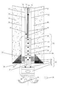
Figure 1 is a vertical cross-section of concentric coiled tubing drill string
03 useful for
drilling a well bore in hydrocarbon formations according to the present
invention.
Concentric coiled tubing drill string 03 comprises an inner coiled tubing
string 01
having an inside wall 70 and an outside wall 72 and an outer coiled tubing
string 02
having an inside wall 74 and an outside wall 76. The inner coiled tubing
string 01 is
inserted inside the outer coiled tubing string 02. The outer coiled tubing
string 02
typically has an outer diameter of 73.Omm or 88.9mm, and the inner coiled
tubing
string 01 typically has an outer diameter of 38.1 mm, 44.5mm, or 50.8mm. Other
diameters of either string may be run as deemed necessary for the operation.
Concentric coiled tubing drill string annulus 30 is formed between the outside
wall 72
of the inner coiled tubing string 01 and the inside wall 74 of the outer
coiled tubing
string 02.
Concentric coiled tubing drill string 03 is connected to bottom hole assembly
22, said
bottom hole assembly 22 comprising a reverse-circulating drilling assembly 04
and a
reverse-circulating motor head assembly 05. Reverse circulating motor head
assembly 05 comprises concentric coiled tubing connector 06 and, in preferred
embodiments, further comprises a downhole blowout preventor or flow control
means 07, disconnecting means 08, and rotating sub 09. Reverse-circulating
drilling
assembly 04 comprises impact or drilling bit 78 and impact hammer 80.
Rotating sub 09 rotates the reverse-circulation drilling assembly 04 to ensure
that
9
SUBSTITUTE SHEET (RULE 26)
CA 02473372 2004-07-13
WO 03/062590 PCT/CA03/00048
drilling bit 78 doesn't strike at only one spot in the well bore.
Disconnecting means
08 provides a means for disconnecting concentric coiled tubing drill string 03
from
the reverse-circulation drilling assembly 04 should it get stuck in the well
bore.
Downhole flow control means 07 enables flow from the well bore to be shut off
through either or both of the inner coiled tubing string 01 and the concentric
coiled
tubing drill string annulus 30 between the inner coiled tubing string 01 and
the outer
coiled tubing string 02. Concentric coiled tubing connector 06 connects outer
coiled
tubing string 02 and inner coiled tubing string 01 to the bottom hole assembly
22. It
should be noted, however, that outer coiled tubing string 02 and inner coiled
tubing
string 01 could be directly connected to reverse-circulation drilling assembly
04.
Flow control means 07 operates by means of two small diameter capillary tubes
10
that are run inside inner coiled tubing string 01 and connect to closing
device 07.
Hydraulic or pneumatic pressure is transmitted through capillary tubes 10 from
surface. Capillary tubes 10 are typically stainless steel of 6.4mm diameter,
but may
be of varying material and of smaller or larger diameter as required.
Drilling medium 28 is pumped through concentric coiled tubing drill string
annulus 30,
through the motor head assembly 05, and into a flow path 36 in the reverse-
circulating drilling assembly 04, while maintaining isolation from the inside
of the
inner coiled tubing string 01. The drilling fluid 28 powers the reverse-
circulating
drilling assembly 04, which drills a hole in the casing 32, cement 33, and/or
hydrocarbon formation 34 resulting in a plurality of drill cuttings 38.
Exhaust drilling medium 35 from the reverse-circulating drilling assembly 04
is, in
whole or in part, drawn back up inside the reverse-circulating drilling
assembly 04
through a flow path 37 which is isolated from the drilling fluid 28 and the
flow path
36. Along with exhaust drilling medium 35, drill cuttings 38 and formation
fluids 39
are also, in whole or in part, drawn back up inside the reverse-circulating
drilling
assembly 04 and into flow path 37. Venturi 82 aids in accelerating exhaust
drilling
medium 35 to ensure that drill cuttings are removed from downhole. Shroud 84
is
located between impact hammer 80 and inner wall 86 of well bore 32 in
relatively air
tight and frictional engagement with the inner wall 86. Shroud 84 reduces
exhaust
SUBSTITUTE SHEET (RULE 26)
CA 02473372 2004-07-13
WO 03/062590 PCT/CA03/00048
drilling medium 35 and drill cuttings 38 from escaping up the well bore
annulus 88
between the outside wall 76 of outer coiled tubing string 02 and the inside
wall 86 of
well bore 32 so that the exhaust drilling medium, drill cuttings 38, and
formation
fluids 39 preferentially flow up the inner coiled tubing string 01. Exhaust
drilling
medium 35, drill cuttings 38, and formation fluids 39 from flow path 37 are
pushed to
surface under formation pressure.
In another embodiment of the present invention, drilling medium can be pumped
down inner coiled tubing string 01 and exhaust drilling medium carried to the
surface
of the well bore through concentric coiled tubing drill string annulus 30.
Reverse
circulation of the present invention can use as a drilling medium air,
drilling muds or
drilling fluids or a combination of drilling fluid and gases such as nitrogen
and air.
Figure 2 shows a preferred embodiment of the present method and apparatus for
safely drilling a natural gas well or any well containing hydrocarbons using
concentric
coiled tubing drilling. Concentric coiled tubing drill string 03 is run over a
gooseneck
or arch device 11 and stabbed into and through an injector device 12. Arch
device
11 serves to bend concentric coiled tubing string 03 into injector device 12,
which
serves to push the concentric coiled tubing drill string into the well bore,
or pull the
concentric coiled tubing string 03 from the well bore as necessary to conduct
the
operation. Concentric coiled tubing drill string 03 is pushed or pulled
through a
stuffing box assembly 13 and into a lubricator assembly 14. Stuffing box
assembly
13 serves to contain well bore pressure and fluids, and lubricator assembly 14
allows
for a length of coiled tubing or bottomhole assembly 22 to be lifted above the
well
bore and allowing the well bore to be closed off from pressure.
As was also shown in Figure 1, bottom hole assembly 22 is connected to the
concentric coiled tubing drill string 03. Typical steps would be for the motor
head
assembly 05 to be connected to the concentric coiled tubing drill string 03
and pulled
up into the lubricator assembly 14. Reverse-circulating drilling assembly 04
is
connected to motor head assembly 05 and also pulled into lubricator assembly
14.
Lubricator assembly 14 is manipulated in an upright position directly above
the
wellhead 16 and surface blowout preventor 17 by means of crane 18 with a cable
11
SUBSTITUTE SHEET (RULE 26)
CA 02473372 2004-07-13
WO 03/062590 PCT/CA03/00048
and hook assembly 19. Lubricator assembly 14 is attached to surface blowout
preventor 17 by a quick-connect union 20. Lubricator assembly 14, stuffing box
assembly 13, and surface blowout preventor 17 are pressure tested to ensure
they
are all capable of containing expected well bore pressures without leaks.
Downhole
flow control means 07 is also tested to ensure it is capable of closing from
surface
actuated controls (not shown) and containing well bore pressure without leaks.
Surface blowout preventor 17 is used to prevent a sudden or uncontrolled flow
of
hydrocarbons from escaping from the well bore annulus 88 between the inner
well
bore wall 86 and the outside wall 76 of the outer coiled tubing string 02
during the
drilling operation. An example of such a blowout preventor is Texas Oil Tools
Model
# EG72-T004. Surface blowout preventor 17 is not equipped to control
hydrocarbons flowing up the inside of concentric coiled tubing drill string,
however.
Figure 3 is a schematic drawing of the operations used for the removal of
exhaust
drilling medium out of the well bore. Suction compressor 41 or similar device
may be
placed downstream of the outlet rotating joint 40 to maintain sufficient fluid
velocity
inside the inner coiled tubing string 01 to keep all solids moving upwards and
flowed
through an outlet rotating joint 40. This is especially important when there
is
insufficient formation pressure to move exhaust medium 35, drill cuttings 38,
and
formation fluids 39 up the inner space of the inner coiled tubing string 01.
Outlet
rotating joint 40 allows exhaust medium 35, drill cuttings 38, and formation
fluids 39
to be discharged from the inner space of inner coiled tubing string 01 while
maintaining pressure control from the inner space, without leaks to atmosphere
or to
concentric coiled tubing drill string annulus 30 while moving the concentric
coiled
tubing drill string 03 into or out of the well bore.
Upon completion of pressure testing, wellhead 16 is opened and concentric
coiled
tubing drill string 03 and bottom hole assembly 22 are pushed into the well
bore by
the injector device 12. A hydraulic pump 23 may pump drilling mud or drilling
fluid 24
from a storage tank 25 into a flow line T-junction 26. In the alternative, or
in
combination, air compressor or nitrogen source 21 may also pump air or
nitrogen 27
into a flow line to T-junction 26. Therefore, drilling medium 28 can consist
of drilling
12
SUBSTITUTE SHEET (RULE 26)
CA 02473372 2004-07-13
WO 03/062590 PCT/CA03/00048
mud or drilling fluid 24, gas 27, or a commingled stream of drilling fluid 24
and gas
27 as required for the operation.
Drilling medium 28 is pumped into the inlet rotating joint 29 which directs
drilling
medium 28 into concentric coiled tubing drill string annulus 30 between inner
coiled
tubing string 01 and outer coiled tubing string 02. Inlet rotating joint 29
allows drilling
medium 28 to be pumped into concentric coiled tubing drill string annulus 30
while
maintaining pressure control from concentric coiled tubing drill string
annulus 30,
without leaks to atmosphere or to inner coiled tubing string 01, while moving
concentric coiled tubing drill string 03 into or out of the well bore.
Exhaust drilling medium 35, drill cuttings 38, and formation fluids 39 flow
from the
outlet rotating joint 40 through a plurality of piping and valves 42 to a
surface
separation system 43. Surface separation system 43 may comprise a length of
straight piping terminating at an open tank or earthen pit, or may comprise a
pressure vessel capable of separating and measuring liquid, gas, and solids.
Exhaust medium 35, drill cuttings 38, and formation fluids 39, including
hydrocarbons, that are not drawn into the reverse-circulation drilling
assembly may
flow up the well bore annulus 88 between the outside wall 76 of outer coiled
tubing
string 02 and the inside wall 86 of well bore 32. Materials flowing up the
well bore
annulus 88 will flow through wellhead 16 and surface blowout preventor 17 and
be
directed from the blowout preventor 17 to surface separation system 43.
Figure 4a is a vertical cross-section of downhole flow control means 07 in
open
position and Figure 4b is a vertical cross-section of downhole flow control
means 07
in closed position. Downhole flow control means 07 may be required within
motor
head assembly 05 to enable flow from the well bore to be shut off through
either or
both of the inner coiled tubing string 01 or the concentric coiled tubing
drill string
annulus 30. For effective well control, the closing device should be capable
of being
operated from surface by a means independent of the well bore conditions, or
in
response to an overpressure situation from the well bore.
Referring first to Figure 4a, the downhole flow control means 07 allows
drilling
13
SUBSTITUTE SHEET (RULE 26)
CA 02473372 2004-07-13
WO 03/062590 PCT/CA03/00048
outer coiled tubing string 02 and the inner coiled tubing string 01 are
connected to
bottom hole assembly by means of concentric coiled tubing connector 06. First
connector cap 49 is placed over outer coiled tubing string 02. First external
slip rings
50 are placed inside first connector cap 49, and are compressed onto outer
coiled
tubing string 02 by first connector sub 51, which is threaded into first
connector cap
49. Inner coiled tubing string 01 is extended through the bottom of first
connector
sub 51, and second connector cap 52 is placed over inner coiled tubing string
01 and
threaded into first connector sub 51. Second external slip rings 53 are placed
inside
second connector cap 52, and are compressed onto inner coiled tubing string 01
by
second connector sub 54, which is threaded into second connector cap 52. First
connector sub 51 is ported to allow flow through the sub body from concentric
coiled
tubing drill string annulus 30.
Figure 6 is a schematic diagram of a coiled tubing bulkhead assembly. Drilling
medium 28 is pumped into rotary joint 29 to first coiled tubing bulkhead 55,
which is
connected to the concentric coiled tubing drill string 03 by way of outer
coiled tubing
string 02 and ultimately feeds concentric coiled tubing drill string annulus
30. First
coiled tubing bulkhead 55 is also connected to inner coiled tubing string 01
such that
flow from the inner coiled tubing string 01 is isolated from concentric coiled
tubing
drill string annulus 30. Inner coiled tubing string 01 is run through a first
packoff
device 56 which removes it from contact with concentric coiled tubing drill
string
annulus 30 and connects it to second coiled tubing bulkhead 57. Flow from
inner
coiled tubing string 01 flows through second coiled tubing bulkhead 57,
through a
series of valves, and ultimately to outlet rotary joint 40, which permits flow
from inner
coiled tubing string 01 under pressure while the concentric coiled tubing
drill string
03 is moved into or out of the well. Flow from inner coiled tubing string 01,
which
comprises exhaust drilling medium 35, drill cuttings 38 and formation fluid
39,
including hydrocarbons, is therefore allowed through outlet rotary joint 40
and
allowed to discharge to the surface separation system.
An additional feature of second coiled tubing bulkhead 57 is that it provides
for the
insertion of one or more smaller diameter tubes or devices, with pressure
control,
into the inner coiled tubing string 01 through second packoff 58. In the
preferred
SUBSTITUTE SHEET (RULE 26)
CA 02473372 2004-07-13
WO 03/062590 PCT/CA03/00048
embodiment, second packoff 58 provides for two capillary tubes 10 to be run
inside
the inner coiled tubing string 01 for the operation and control of downhole
flow
control means 07. The capillary tubes 10 are connected to a third rotating
joint 59,
allowing pressure control of the capillary tubes 10 while rotating the work
reel.
While various embodiments in accordance with the present invention have been
shown and described, it is understood that the same is not limited thereto,
but is
susceptible of numerous changes and modifications as known to those skilled in
the
art, and therefore the present invention is not to be limited to the details
shown and
described herein, but intend to cover all such changes and modifications as
are
encompassed by the scope of the appended claims.
16
SUBSTITUTE SHEET (RULE 26)