Note: Descriptions are shown in the official language in which they were submitted.
CA 02474388 2009-12-22
EXTERNAL FIXATION SYSTEM
Field of the Invention
This invention relates generally to methods, systems, and devices for
orthopedic external fixation and more particularly to an external fixation
system
having an improved fixation component for constructing a stable, adjustable
fixation
system that cooperates with other systems, and methods of use thereof.
Background of the Invention
Surgeons use external fixation systems regularly to treat certain bony
skeletal
injuries or conditions, such as acute fractures of the skeleton, soft tissue
injuries,
delayed union of the skeleton when bones are slow to heal, nonunion of the
skeleton
when bones have not healed, malunion of broken or fractured bones, congenital
deformities resulting in malposition of bone, and bone lengthening, widening,
or
twisting. Treatment of these conditions often includes stabilization and
reduction
using an external fixation system. These systems may include a frame comprised
of
one or more of fixation components and one or more fixation elements. As used
herein, fixation component refers to a device for positioning one or more
parts of an
external fixation system, and fixation element refers to one or more of a bar,
rod,
wire, or pin used in an external fixation system. Wires may be threaded,
beaded, or
smooth, and pins may be threaded or smooth. Generally, one or more bone pins
or
wires are inserted into the tissue and bone and then the remainder of the
fixation
system is assembled. It is often important that a surgeon is able to place the
external
fixation system on the patient and then reduce the fracture in an expedited
manner.
Fracture patterns are infinite and may require the fixation system to move in
multiple
planes simultaneously in order to stabilize and reduce the fracture properly.
Current external fixation system designs vary, but generally include a
mechanism for attaching at least one fixation element to a fixation component
to form
a construct, or frame, to support a fracture. In general, at least one pin or
wire is
drilled into the bone. Bone pins typically have one end that is either or both
self-
CA 02474388 2010-08-13
drilling and self-tapping, and have a diameter sufficient to resist bending.
Bone wires
are generally smaller in diameter. Bone pins or wires may be drilled
completely
through the bone, exiting the skin on the opposite side of the bone, called
"transflxation pins," or may extend through the bony skeleton and out only one
side
of the limb, called "half pins." Current fixation components generally either
connect
a bar to a bar, a bar to a wire, or a bar to a pin. The frame of an external
fixation
system may include unilateral bars, which extend along the side of a patient's
body, or
circumferential or half rings, which encircle a patient's body member entirely
or in
part. Systems designed to use a circumferential ring or half ring include the
ILIZAROVTM brand system and the SPATIAL FR.AMETM brand system. The
SPATIAL FRAMETM brand system is described in U.S. Patent No. 5,702,389.
Generally, circumferential and half rings have a rectangular cross-section.
When stabilizing and reducing a fracture using an external fixation system, it
is important to properly align the bone fragments. Such alignment requires a
fixation
component that securely joins the pins and wires to the bars, but, that is
readily,
adjustable. In many cases, two pins are inserted below the fracture and two
pins are
inserted above the fracture. The surgeon then attaches a fixation component to
each
pin, bridging the fixation components together with rods, or bars. These bars
form the
frame of the external fixation system. As additional fixation components are
added to
the system in different planes, the frame becomes less adjustable. Current
fixation
systems permit a surgeon to choose the'positioning of only two fixation
components
because after placement of two components, additional fixation components will
only
fit into set positions. During a procedure, it is often necessary to further
reduce a
fracture, which requires removal of the bars (and loss of positioning) and
then
replacement of the bars in the frame. Thus; additional reduction is difficult
to achieve
and requires reestablishment of optimal position. Current systems are also
highly
dependent on accurate pin or wire placement. For example, if the pins or wires
are'
angled incorrectly, the frame cannot be properly constructed.
One current external fixation component design includes two clamps that
rotate in one plane to allow limited manipulation of the external fixation
component.
One jaw of each clamp of this design includes a toothed chip mechanism that
has a
surface with teeth similar to a poker chip. The teeth mate and lock when
compressed,
2
CA 02474388 2004-08-03
WO 03/065911 PCT/US03/02712
and thereby resist rotation in one plane after the clamps are in place. This
poker chip
design requires that the two fixation elements retained by the component are
parallel
to each other in at least one plane that is parallel to the poker chip
surface, so that the
angular relationship between the two fixation elements is always zero in that
plane.
Therefore, this system requires a parallel plane between the pin or wire and
bar (or
between two bars) for each fixation component. This requirement limits the
system,
as the positioning of each clamp is inhibited. Similar to other current
designs, this
design becomes substandard when several fixation components are used because
it
becomes constrained.
In addition, the clamps of many current designs are adjacent a central shaft
and are both locked upon tightening of a single screw, further constraining
the system.
Many current designs also allow for placement of the pins in the pin clamp of
a
fixation element only from the side and require a bent bar for placement of
the system
proximate the patient, if it is necessary to conform the system to the
patient's
anatomy. In addition, current designs use compression to hold the bar or pin
in place,
and may allow dislodgement of the pin or bar upon application of a great
amount of
pressure to the system when being placed.
Other prior art designs include circumferential rings or half rings, such as
those in the ILIZAROVTM and SPATIAL FRAMETM brand systems. These
specialized systems are often used for reduction of a fracture of the proximal
tibia or
distal femur. Generally, wires connected to half rings are used to stabilize a
fracture.
These specialized systems do not cooperate with general external fixation
systems,
and must be used separately.
Thus, there is a need for an external fixation system that provides a greater
degree of freedom of rotation of the fixation components and therefore a more
flexible frame construct, sequential locking of capture members, allowing
greater
adjustability, and cooperation with specialized fixation systems.
Summary of the Invention
An external fixation system according to one embodiment of this invention
allows manipulation of an external fixation component in any plane independent
of
the number of fixation components used, which, is provided by the ability of
the
fixation component to rotate in multiple planes. Further, an improved fixation
3
CA 02474388 2004-08-03
WO 03/065911 PCT/US03/02712
component according to one embodiment of this invention provides an external
fixation system that does not bind or become constricted when numerous
fixation
components are used, providing the surgeon a stable system that is adjustable.
One embodiment of a fixation component according to this invention includes
two capture members, a first capture member adapted to capture a first
fixation
element and a second capture member adapted to capture a second fixation
element.
The capture members are coupled such that the coupling allows the first
capture
member and second capture member to rotate about three axes relative to each
other
and the second capture member to rotate about one axis of the second fixation
element
and move along that axis. The coupling is adapted to secure the first and
second
capture members from rotation and secure the second capture member from
rotating
about and moving along the axis of the second fixation element with a single
activation. The second capture member is adapted to capture the second
fixation
element by snapping onto the second element from substantially perpendicular
to the
longitudinal axis of the second element.
One feature of one embodiment of this invention is a fixation component that
provides a greater degree of freedom of rotation.
Another feature of one embodiment of this invention is a fixation component
that simultaneously locks a capture member to a fixation element and locks the
joint
between two capture members.
Another feature of one embodiment of this invention is a modular design
whereby at least one of the two capture members of a fixation component may be
interchangeable with another capture member. For example, if a fixation
component
has two capture members each for receiving a bar, the two capture members may
be
separated at the joint, and another capture member, for receiving a pin, may
be
attached to one of the original two capture members to form a fixation
component
with one capture member for receiving a bar and the other capture member for
receiving a pin.
Yet another feature is a fixation component that allows one capture member to
be locked to retain a fixation element without forcing the second capture
member also
to be locked, allowing additional adjustment of position of the second capture
member.
4
CA 02474388 2004-08-03
WO 03/065911 PCT/US03/02712
Another feature of one embodiment according to this invention is a fixation
component having a locking mechanism that is not dislodged by application
pressure.
Yet another feature of one embodiment of this invention is a fixation
component that cooperates with specialized fixation systems.
According to the present invention there is provided an external fixation
component comprising (a) a first capture member adapted to capture a first
element of
an orthopedic fixation system; and (b) a second capture member adapted to
capture a
second element of an orthopedic fixation system and coupled to the first
capture
member such that the coupling allows the first capture member and the second
capture member to rotate about three axes relative to each other and the
second
capture member to rotate about one axis of the second element and move along
that
axis; wherein the coupling is adapted to secure the first and second capture
members
from rotation with an activation; and wherein the second capture member is
adapted
to capture the second element by snapping onto the second element from
substantially
perpendicular to the longitudinal axis of the second element.
According to the present invention there is provided a method of treating a
skeletal condition or injury using an external fixation system, the method
comprising:
(a) inserting a first fixation element into a bone; (b) capturing the first
fixation
element in a first fixation component by snapping onto the first fixation
element from
substantially perpendicular to the longitudinal axis of the first fixation
element, the
first fixation component comprising: (i) a first capture member adapted to
capture an
element of an orthopedic fixation system; and (ii) a second capture member
adapted
to capture an element of an orthopedic fixation system and coupled to the
first capture
member such that the coupling allows the first capture member and the second
capture member to rotate about three axes relative to each other; wherein the
coupling
is adapted to secure the first and second capture members from rotation with a
single
activation; (c) capturing a second fixation element in the first fixation
component by
snapping onto the second fixation element from substantially perpendicular to
the
longitudinal axis of the second fixation element; and (d) engaging the single
activation to secure the first and second capture members from rotation.
5
CA 02474388 2004-08-03
WO 03/065911 PCT/US03/02712
Brief Description Of The Drawings
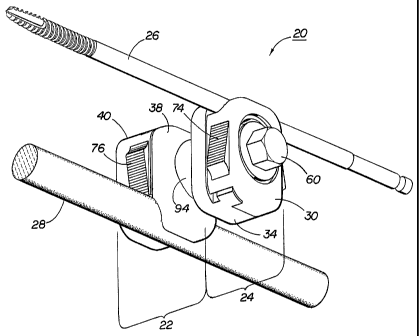
Figure 1 is a perspective view of a fixation component according to one
embodiment of this invention.
Figure 2 is an exploded perspective view of the fixation component of Figure
1.
Figure 3 is a perspective view of the fixation component of Figure 1 with a
pin
and bar inserted.
Figure 4 is a cross-sectional view of the fixation component taken along lines
4-4 in Figure 1.
Figure 5 is a cross-sectional view of the fixation component taken along lines
5-5 in Figure 1.
Figure 6 is an exploded perspective view of the second capture member of
Figure 1.
Figure 7 is a perspective view of a fixation component according to an
alternative embodiment of this invention.
Figure 8 is an exploded perspective view of the fixation component of Figure
7.
Figure 9 is a perspective view of the fixation component of Figure 7, with
bars
inserted in the capture members.
Figure 10 is a perspective view of a fixation component according to an
alternative embodiment of this invention.
Figure 11 is an exploded perspective view of the fixation component of Figure
10.
Figure 12 is a perspective view of an external fixation system according to
one
embodiment of this invention.
Figure 13 is an enlarged fragmentary perspective view of selected fixation
components of Figure 12.
Figure 14 is an exploded perspective view of an alternative embodiment of
this invention.
Figure 15 is a plan view of the fixation component of Figure 14.
Figure 16 is a cross-sectional view of the fixation component of Figure 14
taken along lines 16-16 of Figure 15.
6
CA 02474388 2004-08-03
WO 03/065911 PCT/US03/02712
Figure 17 is an exploded perspective view of an alternative embodiment of
this invention.
Figure 18 is a plan view of the fixation component of Figure 17.
Figure 19 is a cross-sectional view of the fixation component of Figure 17
taken along lines 19-19 of Figure 18.
Detailed Description of the Invention
Methods, systems, and devices according to this invention seek to provide
improved external fixation, including an improved fixation component allowing
an
increase in freedom of rotation, independent locking of capture members, a
more
stable, yet more flexible frame, and cooperation with specialized fixation
systems.
External fixation systems according to embodiments of this invention may
include
fixation components designed to retain one or more fixation elements. In
general, the
fixation components either connect a bar to a bar; a bar to a pin; a bar to a
wire; or a
bar to a circumferential or half ring. Each fixation component generally
includes two
capture members, and each capture member includes a base and a head.
One embodiment of a fixation component according to this invention includes
a first capture member and a second capture member connected by a joint. Each
capture member includes a channel, which allows attachment of a fixation
element
20, from the side. Prior to being locked down, each fixation element can slide
(back and
forth) and rotate within the channel providing two degrees of freedom between
the
fixation element and the capture member. The first and second capture members
are
connected by a joint that allows each capture member to rotate with respect to
the
other capture member. The joint also allows rotation of up to 50 in any plane
(25
each way), increasing the degree of freedom of rotation. In one embodiment,
angulation is limited to 50 due to profile height constraints. However, in
another
embodiment more angulation may be provided. Thus, each capture member is
provided three degrees of rotational freedom relative to the other capture
member. An
external fixation system including fixation components according to this
invention
allows movement of the bone along six separate axes, a combination of three
orthogonal translational axes and three orthogonal rotational axes.
In one embodiment according to this invention, a fixation component having a
unique joint allows simultaneous locking of one capture member and the joint.
In
7
CA 02474388 2004-08-03
WO 03/065911 PCT/US03/02712
addition, one capture member may be locked in place while the second capture
member continues to freely rotate. In this manner, the surgeon is able to lock
one
capture member and continue to rotate the second capture member for final
positioning. The surgeon is also able to loosen only one capture member to
gain
additional reduction, if required, without losing placement, as occurs with
current
systems when additional reduction is required.
Consider one example of systems and devices according to this invention. As
shown in Figures 1-6, a bar-to-pin fixation component 20 includes a first
capture
member 24 and a second capture member 22. First capture member 24 retains a
pin
26, while second capture member 22 is configured to retain a bar 28, as shown
in
Figure 3. A base 30 of first capture member 24 includes a groove 32, while a
head 34
of first capture member 24 contains a wedge 36, which together are adapted to
retain
pin 26. Likewise, a base 38 and a head 40 of second capture member 22 include
a
groove 42 and a wedge 44, together adapted to retain bar 28. In one
embodiment,
groove 42 of second capture member 22 has splines 46, which provide rotational
stability of bar 28 and penetrate the surface of bar 28 when second capture
member 22
is tightened. Alternatively, the second capture member may be adapted to
retain a pin
and the first capture member may be adapted to retain a bar. In an alternative
embodiment, both the first and second capture members are configured to retain
a bar,
as shown in Figures 7-9 . In another embodiment, one capture member is adapted
to
retain a wire, while the other capture member is adapted to retain a bar. In
another
embodiment, the capture members are modular allowing for each capture member
to
be connected to a similarly designed capture member. Additional embodiments
are
further described below.
As shown in Figure 2, head 34 of first capture member 24 has a recess 48
adapted to receive a spring 50, while base 30 of first capture member 24
includes a
stop 52. A first track 54 on each side of head 34 slides in a second track 56
on each
side of base 30, allowing head 34 and base 30 of first capture member 24 to
translate
with respect to each other. In an alternative embodiment, second track 56
slides in
first track 54. In one embodiment, one of first and second tracks 54, 56 is an
L-
shaped track, while the other track is shaped to receive the L-shaped track.
As a force
in a direction perpendicular to the pin is exerted against groove 32 and wedge
36 of
first capture member 24, head 34 moves, compressing spring 50 against the
extended
8
CA 02474388 2004-08-03
WO 03/065911 PCT/US03/02712
portion of base 30. Spring 50 compresses until it exerts a force in a
direction
perpendicular to pin 26 that is equal and opposite to the force exerted
against wedge
36. At that point, head 34 stops moving and holds pin 26 in groove 32 and
wedge 36,
which together form channel 58.
The angular position of channel 58 is set by tightening a first fastener 60.
Prior to tightening of first fastener 60, the cartridge mechanism, in the
loosened state,
does not allow pin 26 to passively separate or detach from capture member 24.
Base
30 of first capture member 24 includes an elevated portion 61, as shown in
Figure 4,
forcing two points of contact between base 30 and head 34 in order to increase
the
holding power of first capture member 24. Base 38 of second capture member 22
also
includes an elevated portion 63, also shown in Figure 4, which increases the
holding
power of second capture member 22 in the same manner.
Second capture member 22 also includes a cartridge mechanism for retaining
bar 28. Head 40 of second capture member 22 has a recess 62 adapted to receive
a
spring 64, while base 38 of second capture member 22 includes a stop 66. A
first
track 68 on each side of head 40 slides in a second track 70 on each side of
base 38.
In an alternative embodiment, second track 70 slides in first track 68. In one
embodiment, one of first and second tracks 68, 70 is an L-shaped track, while
the
other track is shaped to receive the L-shaped track. Groove 42 and wedge 44 of
second capture member form a second capture member channel 72, which receives
a
bar 28. Bar 28 is retained in second capture member 22 in the same manner as
first
capture member 24 retains pin 26.
In an alternative embodiment, one or both capture members may include two
recesses for receiving two springs and two spring stops. In the embodiments
shown,
the recess, spring, and stop are located on one side of the capture member. In
an
alternative embodiment, the recess, spring, and spring stop are in the middle
of the
capture member, or are on the other side of the capture member. In one
embodiment,
heads 40 and 34 of capture members 22 and 24, respectively, include grip
surfaces 74
and 76 for gripping and sliding heads 40 and 34 in relation to bases 38 and
30,
respectively. In one embodiment, grip surfaces 74 and 76 include ridges.
A threaded end 78 of first fastener 60 is adjacent a biasing element, such as
a
center spring 80, and passes through a keyhole aperture 82 in head 34 of first
capture
member 24, mating to internal threads 84 in base 30 of first capture member
24.
9
CA 02474388 2004-08-03
WO 03/065911 PCT/US03/02712
Keyhole aperture 82 of head 34 if first capture member 24 allows a reduced
diameter
neck 85 of first fastener 60 to translate within the aperture 82. Tightening
of first
fastener 60 locks first capture member 24 and rigidly retains pin 26. In an
alternative
embodiment, aperture 82 is circular, or any other suitable shape.
A connector 86 having an end 88 and a shaft 90 extends through a keyhole
aperture 92 in base 30 of first capture member 24. In one embodiment,
connector 86
is a ball stud, as shown in Figure 2, having a spherical end. End 88 of
connector 86 is
received in a planetary member 94 of base 30 of first capture member 24. As
used
herein, a planetary member refers to an object that is received in another
object, and
that receives another object within itself. In one embodiment, planetary
member 94 is
an outer sphere, as shown in the figures. Shaft 90 of connector 86 extends
through an
aperture 96 in base 38 of second capture member 22 and an aperture 98 in head
40 of
second capture member 22, and mates with a second fastener 100. Threads 102 on
shaft 90 of connector 86 mate with internal threads 104 of second fastener
100.
A slot 106 in aperture 96 of base 38 of second capture member 22 is adapted
to receive a key 108 on shaft 90 of connector 86. Key 108 and slot 106 thus
prevent
rotation of connector 86 within second capture member 22. In another
embodiment,
any suitable mechanism for preventing rotation of the connector is used. In
other
words, the connector fits through the base of the first capture member and the
end is
received in the planetary member of the base, while the shaft of the connector
extends
through both the base and head of the second capture member and threads to a
second
fastener. A planetary member, for example outer sphere 94, fits within a
cooperating
surface 110, which is machined into the one side of base 38 of second capture
member 22. Tightening of second fastener 100 on second capture member 22 draws
connector 86 into planetary member 94, locking the second capture member and
the
joint to make it rigid. In one embodiment, one or both of the planetary member
and
cooperating surface may be tapered. For example, a taper of 10 , 15 , 20 , or
30 may
be used on each.
The joint mechanism described above allows the second capture member to
rotate with respect to the planetary member of the first capture member, and
allows
the first capture member to grasp and lock a pin while permitting the second
capture
member to continue to rotate. Independent tightening of the capture members
provides the surgeon flexibility to snap a fixation element to a capture
member and
CA 02474388 2004-08-03
WO 03/065911 PCT/US03/02712
then to manipulate the second capture member before locking the second capture
member in order to achieve a more stable frame. In this manner, independent
tightening of each capture member of the external fixation component allows
more
precise angular positioning. Alternative embodiments of a joint mechanism
between
two capture members are described below with reference to Figures 14-19.
Other embodiments, such as a bar-to-bar fixation component, shown in
Figures 7-9, and a bar-to-wire fixation component, also may contribute to a
more
stable, more adjustable external fixation system. These embodiments function
similarly to the bar-to-pin fixation component, with the capture members
having a
wedge and groove adapted to form a channel sized for receiving either a bar or
a wire,
depending on the component.
In one embodiment, a cartridge locking of the pin and bar is provided, as
described above. However, in alternative embodiments, other one-piece designs
may
be used. For example, a solid piece of aluminum metal having the shape of the
two
part head and base cartridge construct of the two capture members may be used.
This
one-piece design includes a channel in each one piece capture member and a
slot that
extends close to the rear portion of the capture member. The slot causes the
material
to behave similar to a spring and allows the capture member to open when
pressure is
placed against it, so that a fixation element may be snapped into place in the
channel.
Several mechanisms may be used to improve the locking capabilities of the
joint. Coatings or elastic materials or alternate taper shapes may be applied
to any of
the articulating surfaces. For example, coatings or elastic materials or
alternate taper
shapes may be applied to one or both of the planetary member and cooperating
surface so that a textured surface on either or both improves locking. In one
embodiment, the cooperating surface is coated with SC729, a coating
manufactured
by Hitemco. In this embodiment, the cooperating surface is very rough and is
made
from tungsten cobalt carbide. In this embodiment, the value for slip increases
to
about 240 in.-lb., from about 140 in.-lb. without the coating. In an
alternative
embodiment, a mechanical locking pattern is applied. For example, splines and
dimples may be added to one or both of planetary member and cooperating
surface,
providing teeth to grab when locking, thereby improving the locking function.
A 30
degree chosen taper configuration on the inside of the planetary member mating
surface uses a taper design to achieve torque strength of up to 200 in.-lb.
11
CA 02474388 2004-08-03
WO 03/065911 PCT/US03/02712
In an alternative embodiment, a fixation component is designed for attachment
to a circumferential external fixator system, such as an ILIZAROVTM brand
system, a
SPATIAL FRAMETM brand system, or other spatial frame, to achieve a hybrid
external construct. In this embodiment, shown in Figures 10-11, the fixation
component includes a capture member for retaining a bar and a capture member
for
retaining a half or circumferential ring having a generally rectangular cross-
section.
Use of a fixation component having a capture member for retaining a ring
allows a
surgeon to create a hybrid frame, using both a standard external fixation
system and a
system that includes a circumferential external frame. This hybrid system is
very
useful in adapting a system for treating a shaft fracture, or typical in-line
fracture, to
one for treating a plateau fracture, which is a fracture in a joint space.
Referring to Figures 10 and 11, a T-component 112 according to one
embodiment of a fixation component of this invention includes a second capture
member 114 that is similar to the second capture member described above with
respect to the bar-to-pin fixation component. A head 116 of second capture
member
114 has a recess 118 adapted to receive a spring 120, while a base 122 of
second
capture member 114 includes a stop 124. Recess 118 and spring 120 function as
described above. Second capture member 114 also includes a first track 126 and
a
second track 128 so that head 116 and base 122 translate and retain a bar in a
groove
130 and a wedge 132 in the same manner as described above.
Base 122 of second capture member 114 also includes a cooperating surface
134, which is adapted to receive a planetary member 136 of a first capture
member
156. A connector 138, which, as described above and shown in Figure 11, may be
a
ball stud, has a shaft 140 that extends through apertures 142 and 144 in base
122 and
head 116, respectively, of second capture member 114. A slot 146 in aperture
142 of
base 122 is adapted to receive a key 148 on shaft 140 of connector 138 in
order to
prevent rotation of connector 138 within second capture member 114. Threads
150
on shaft 140 mate with a second fastener 152, while an end 154 is received in
planetary member 136.
First capture member 156 includes a base 158 and a head 160, each having a
recess 162 and 164, respectively, that together form a channel 166, adapted to
receive
a ring having a rectangular cross-section. Head 160 has an extension 168 that
fits into
a rim 170 of base 162. A rod 172 includes second threads 174 that mate with
internal
12
CA 02474388 2004-08-03
WO 03/065911 PCT/US03/02712
threads 176 of an aperture 178 of base 158 after extending through an aperture
180 of
head 160. A biasing element 182, such as a spring, passes over rod 172 and
also into
an aperture 184 of a first fastener 186. First threads 188 of rod 172 mate
with internal
threads 190 of first fastener 186. Tightening of first fastener 186 thus locks
base 158
and head 160 of first capture member 156. Second capture member 114 is free to
rotate about planetary member 136 of base 158 of first capture member 156
until
second fastener 152 is tightened, at which time both second capture member 114
and
planetary member 136 and cooperating surface 134, which form the joint, are
locked.
In an alternative embodiment, other locking mechanisms may be used, such as
a universal joint mechanism, which allows independent movement in different
directions. In yet another alternative embodiment, the capture member may
include a
flip through for the bar or pin, rather than a snap-on from the side as
described above.
One embodiment of a fixation component of this invention is made from
titanium and aluminum. In this embodiment, the heads of the capture members
are
made from aluminum and the remaining parts from titanium. In alternative
embodiments, fixation components are made from metals, alloys, plastics,
composites, ceramics, or any other suitable material.
As noted above, additional alternative embodiments of capture members and a
joint mechanism between two capture members are shown in Figures 14-19. One
alternative joint mechanism is shown in Figures 14-16, while another
alternative is
shown in Figures 17-19. The capture members shown in Figures 14-19 generally
perform in a similar manner as the capture members described above with regard
to
the receipt of fixation elements and engagement of the base and head of each
capture
member.
As shown in Figures 14-16, a fixation component 200 includes a first capture
member 202 and a second capture member 230. Capture members 202 and 230 may
be designed to retain one of any of a pin, wire, bar, at least a partial ring,
or other
fixation element., As shown in Figures 14-16, each capture member is designed
to
receive a bar. A base 204 of first capture member 202 includes a groove 206,
while a
head 208 of first capture member 202 contains a wedge 210, which together are
adapted to retain a fixation element. Likewise, a base 232 and a head 234 of
second
capture member 230 include a groove 236 and a wedge 238, together adapted to
retain
a fixation element in the same manner as described above.
13
CA 02474388 2004-08-03
WO 03/065911 PCT/US03/02712
Head 208 of first capture member 202 has a recess (not shown) adapted to
receive a spring 214, while base 204 of first capture member 202 includes a
stop 216.
The recess, spring 214, and stop 216 function in the same manner as described
above.
First capture member 202 also includes a first track 218 and a second track
220 so that
head 208 and base 204 translate and retain a fixation element in a channel 222
formed
by groove 206 and wedge 210 in the same manner as described above. The angular
position of channel 222 is set by tightening a first fastener 224. Prior to
tightening of
first fastener 224, the cartridge mechanism, in the loosened state, does not
allow an
inserted fixation element to passively separate or detach from capture member
202.
Second capture member 230 also includes a cartridge mechanism for retaining
a fixation element. Head 234 of second capture member 230 has a recess 240
adapted
to receive a spring 242, while base 232 of second capture member 230 includes
a stop
244. Second capture member 230 also includes a first track 246 and a second
track
248 so that head 234 and base 232 translate and retain a fixation element in a
channel
250 formed by groove 236 and wedge 238 in the same manner as described above.
The angular position of channel 250 is set by tightening a second fastener
252. Prior
to tightening of second fastener 252, the cartridge mechanism, in the loosened
state,
does not allow an inserted fixation element to passively separate or detach
from
capture member 230.
In the embodiments shown, the recess, spring, and stop are located on one side
of the capture member. In an alternative embodiment, the recess, spring, and
spring
stop are in the middle of the capture member, or are on the other side of the
capture
member. In one embodiment, heads 208 and 234 of capture members 202 and 230,
respectively, include grip surfaces 226 and 254 for gripping and sliding heads
208 and
234 in relation to bases 204 and 232, respectively. In one embodiment, grip
surfaces
226 and 254 include ridges.
A threaded end 256 of second fastener 252 passes through an aperture 258 in
head 234 of second capture member 230, mating to internal threads 260 in base
232 of
second capture member 230. Tightening of second fastener 252 locks second
capture
member 230 and rigidly retains an inserted fixation element.
A connector 270 having an end 272 and a shaft 274 extends through bore 276
in base 204 of first capture member 202. In one embodiment, connector 270 is a
ball
stud, as shown in Figure 14, having a spherical end. End 272 of connector 270
is
14
CA 02474388 2004-08-03
WO 03/065911 PCT/US03/02712
received in a spherical collet 278 of base 204 of first capture member 202.
Shaft 274
of connector 270 extends through bore 276 in base 204 of first capture member
202
and an aperture 280 in head 208 of first capture member 202, and mates with
first
fastener 224. Threads 282 on shaft 274 of connector 270 mate with internal
threads
228 of first fastener 224. A slot 284 in bore 276 of base 204 of first capture
member
202 is adapted to receive a key 286 on shaft 274 of connector 270. Key 286 and
slot
284 thus prevent rotation of connector 270 within first capture member 202.
The end of bore 276 may be tapered or countersunk. When connector 270 is
inserted through the countersunk end of bore 276 and aperture 280 of head 208
of first
capture member 202, end 272 rests against the countersunk end of bore 276.
First
fastener 224 is threaded onto shaft 274 so that as first fastener 224 is
tightened against
capture member 202, end 272 is pulled through base 204 and head 208 of capture
member 202, forcing spherical collet 278 to expand.
A spherical pocket 290 of base 232 of second capture member 230 receives
spherical collet 278. In a loosened state (i.e., first fastener 224 is not
fully tightened
and spherical collet 278 is not fully expanded), spherical collet 278 may be
retained
within spherical pocket 290, and spherical collet 278 may or may not be biased
against spherical pocket 290 to provide resistance for the joint mechanism.
When end
272 of connector 270 is not expanding spherical collet 278, capture members
202 and
230 may be rotated about or detached from each other. When first fastener 224
is
tightened and spherical collet 278 fully expanded, capture members 202 and 230
cannot be rotated about each other or detached from each other. The tightening
of
first fastener 224 locks first capture member 202 and the joint to make it
rigid. In one
embodiment, one or both of the spherical collet and spherical pocket may be
tapered.
For example, a taper of 10 , 15 , 20 , or 30 may be used on each. Several
mechanisms may be used to improve the locking capabilities of the joint,
including
coatings, elastic materials, or alternate taper shapes as discussed above.
The joint mechanism shown in Figures 14-16 allows the first capture member
to rotate with respect to the spherical pocket of the second capture member,
and
allows the second capture member to grasp and lock a fixation element while
permitting the first capture member to continue to rotate. Independent
tightening of
the capture members provides the surgeon flexibility to snap a fixation
element to a
capture member and then to manipulate the first capture member before locking
the
CA 02474388 2004-08-03
WO 03/065911 PCT/US03/02712
first capture member in order to achieve a more stable frame. In this manner,
independent tightening of each capture member of the external fixation
component
allows more precise angular positioning.
In addition to increasing the degrees of freedom of movement of fixation
components and allowing for more precise angular positioning, the use of the
joint
mechanism shown in Figures 14-16 provides a modular external fixation system
for
use by surgeons. Rather than providing pre-assembled fixation components in a
surgical tray, separate capture members, not yet attached to other capture
members to
form fixation components, may be provided. For example, instead of providing a
predetermined number of bar-to-bar fixation components and bar-to-pin fixation
components in a surgical tray, a system may include a specified number of
capture
members for receiving bars and capture members for receiving pins. The capture
members may be connected by the surgeon, or an assistant, using the joint
mechanism
shown in Figures 14-16 to form specific fixation components (e.g., bar-to-bar,
bar-to-
pin, bar-to wire, etc.) as desired based upon the surgery being performed.
This
provides better inventory control and should reduce the number of capture
members
and/or fixation components required to be provided in a surgical tray.
Another alternative embodiment is shown in Figures 17-19. Similar to the
embodiment shown in Figures 14-16, the embodiment shown in Figures 17-19 also
provides better inventory control by using capture members that may be easily
detached and interchanged with other capture members to form the type of
fixation
component desired. However, the embodiment shown in Figures 17-19 also
provides
independent locking of the joint and each capture member rather than providing
the
simultaneously locking of the joint and one of the two capture members as
discussed
with regard to several other embodiments.
As shown in Figures 17-19, a fixation component 300 includes a first capture
member 302 and a second capture member 330. Capture members 302 and 330 may
be designed to retain one of any of a pin, wire, bar, at least a partial ring,
or other
fixation element. As shown in Figures 17-19, each capture member is designed
to
receive a bar. A base 304 of first capture member 302 includes a groove 306,
while a
head 308 of first capture member 302 contains a wedge 310, which together are
adapted to retain a fixation element. Likewise, a base 332 and a head 334 of
second
16
CA 02474388 2004-08-03
WO 03/065911 PCT/US03/02712
capture member 330 include a groove 336 and a wedge 338, together adapted to
retain
a fixation element in the same manner as described above.
Head 308 of first capture member 302 has a recess (not shown) adapted to
receive a spring 314, while base 304 of first capture member 302 includes a
stop 316.
The recess, spring 314, and stop 316 function in the same manner as described
above.
First capture member 302 also includes a first track 318 and a second track
320 so that
head 308 and base 304 translate and retain a fixation element in a channel 322
formed
by groove 306 and wedge 310 in the same manner as described above. The angular
position of channel 322 is set by tightening a first fastener 324. Prior to
tightening of
first fastener 324, the cartridge mechanism, in the loosened state, does not
allow an
inserted fixation element to passively separate or detach from capture member
302.
Second capture member 330 also includes a cartridge mechanism for retaining
a fixation element. Head 334 of second capture member 330 has a recess 340
adapted
to receive a spring 342, while base 332 of second capture member 330 includes
a stop
344. Second capture member 330 also includes a first track 346 and a second
track
348 so that head 334 and base 332 translate and retain a fixation element in a
channel
350 formed by groove 336 and wedge 338 in the same manner as described above.
The angular position of channel 350 is set by tightening a second fastener
352. Prior
to tightening of second fastener 352, the cartridge mechanism, in the loosened
state,
does not allow an inserted fixation element to passively separate or detach
from
capture member 330.
In the embodiments shown, the recess, spring, and stop are located on one side
of the capture member. In an alternative embodiment, the recess, spring, and
spring
stop are in the middle of the capture member, or are on the other side of the
capture
member. In one embodiment, heads 308 and 334 of capture members 302 and 330,
respectively, include grip surfaces 326 and 354 for gripping and sliding heads
308 and
334 in relation to bases 304 and 332, respectively. In one embodiment, grip
surfaces
326 and 354 include ridges.
A threaded end 356 of second fastener 352 passes through an aperture 358 in
head 334 of second capture member 330, mating to internal threads 360 in base
332 of
second capture member 330. Tightening of second fastener 352 locks second
capture
member 330 and rigidly retains an inserted fixation element.
17
CA 02474388 2004-08-03
WO 03/065911 PCT/US03/02712
A set screw 370 including threads 372 is inserted into bore 376 in base 304 of
first capture member 302. In one embodiment, set screw 370 is tapered. End 374
of
set screw 370 is received in a spherical collet 378 of base 304 of first
capture member
302. Threads 372 on set screw 370 mate with internal threads 388 of bore 376
of base
304 of first capture member 302.
A spherical pocket 390 of base 332 of second capture member 330 receives
spherical collet 378. When set screw 370 is tightened, spherical collet 378
expands
and the joint between first and second capture members 302 and 330 is rigid.
In a
loosened state, when set screw 370 is not tightened, spherical collet 378 may
be
retained within spherical pocket 390, and spherical collet 378 may or may not
be
biased against spherical pocket 390 to provide resistance for the joint
mechanism.
Locking of the joint between the two capture members prevents rotation of
either
capture member about each other, but neither capture member is locked by
tightening
of set screw 370. When set screw 370 is partially threaded onto internal
threads 388
of base 304 of first capture member 302 and spherical collet 378 is within
spherical
pocket 390 but not fully expanded, capture members 302 and 330 may be rotated
about each other. Several mechanisms may be used to improve the locking
capabilities of the joint, including coatings, elastic materials, or alternate
taper shapes
as discussed above.
First fastener 324 includes a bore 392 and threads 394. First fastener 324
extends through an aperture 380 in head 308 of first capture member 302 and
threads
394 are threaded onto internal threads 388 of base 304 of first capture member
302.
Tightening of first fastener 324 locks capture member 302. Bore 392 extends
through
first fastener 324, allowing for insertion of a tool 396 to tighten or loosen
set screw
370 in spherical collet 378.
One method of using one form of structure according to this invention, shown
in Figure 13, is as follows:
At least two half pins are self-drilled into a bone, one on either side of a
bone
fracture. One bar-to-pin fixation component is connected to each pin by
placing each
pin into the capture member of each fixation component sized to receive a pin,
such as
the first capture member of the bar-to-pin fixation component shown in Figure
1.
Each fixation element is placed into the fixation component from the side for
easy
placement. After a pin is in place, the first fastener is tightened, so that
the pin is
18
CA 02474388 2004-08-03
WO 03/065911 PCT/US03/02712
retained in the capture member, while the second capture member and joint
continue
to freely rotate. Bars are then snapped into the bar capture member of the
fixation
components, forming a frame for the system. As each bar is added, the fixation
components are adjusted as required by loosening the joint and second capture
member, so that optimal positioning may be obtained. Bar-to-bar fixation
components and bar-to-pin fixation components may be added to expand and
connect
the frame as required. If it is necessary or desirable to utilize a
circumferential ring or
half ring with a system for complex fractures, as shown in Figure 13,
additional
fixation components having capture members designed to retain the rectangular
bar of
a ring are used to join the standard system to the specialized frame. A T-
component
is used to capture the rectangular bar of a ring and link it to a bar of the
original
frame, forming a hybrid system. If additional reduction is required, one
capture
member of any component may be loosened without losing placement of the
system.
A T-component may also be used to provide stability to an existing system that
has
already been placed using standard fixation component designs. A plurality of
clamps
may be used in various configurations to achieve stability for different
fractures.
Similar instrumentation and devices may be used in other areas, such as to
provide a fixed reference to a pin. Constructs made under the present
invention are
stable and provide for a wide variety or placements. Embodiments of an
external
fixation component according to this invention may also be adapted for use
with an
image guided surgery system to provide stability to a reference frame or other
guidance target or mechanism.
The foregoing description of certain exemplary embodiments of the invention
has been presented only for the purposes of illustration and description and
is not
intended to be exhaustive or to limit the invention to the precise forms
disclosed.
Many modifications and variations are possible in light of the above teaching.
The embodiments were chosen and described in order to explain the principles
of the invention and their practical application so as to enable others
skilled in the art
to utilize the invention and various embodiments and with various
modifications as
are suited to the particular use contemplated. Alternative embodiments will
become
apparent to those skilled in the art to which the present invention pertains
without
departing from its spirit and scope. Accordingly, the scope of the present
invention is
19
CA 02474388 2004-08-03
WO 03/065911 PCT/US03/02712
defined by the appended claims rather than the foregoing description and
certain
exemplary embodiments described therein.