Note: Descriptions are shown in the official language in which they were submitted.
CA 02475100 2004-08-03
WO 03/067669 PCT/IL03/00089
SOLAR POWER DEVICES FOR PROVIDING POWER
TO HANDHELD DEVICES
FIELD OF THE INVENTION
The present invention is related to solar power devices which are capable of
performing the conversion of solar energy to electrical energy (photovoltaic
principle), and in particular which are useful for providing power to handheld
devices,
whether indoors (inside of a building or other enclosure) or outdoors (outside
of a
building or other enclosure).
BACKGROUND OF THE INVENTION
The conversion of solar energy to electrical energy through the use of systems
such as photovoltaic cells, arrays, passive absorbers of solar energy, solar
furnaces
etc., is well established in the art. Systems have also been proposed to
converting
solar energy to electric energy; however, these systems employ apparatus which
is
complicated to fabricate, such as sealed outdoor laminated 36 solar cell
enclosures.
For example, U.S: Patent No. 4,080,221 describes a system for converting
solar energy to electric energy, which employs a substantially sealed, weather
tight
enclosure for the solar collectors. U.S. Patent 4,493,940 describes a solar
collector on
which photo voltaic cells are mounted with the assembly being surrounded by an
enclosure that is sealed by a metal sealing collar, and U.S. Patent No.
4,373,308
describes a flat plate solar collector in a spaced relationship to an array of
photovoltaic cells.
Other systems for converting solar energy to electric and DC energy employ
complex methods of transferring solar energy.
None of the above-referenced methods or devices are suitable for the
conversion of solar energy to electrical energy for powering handheld devices,
as
these handheld devices require a sufficiently high level of power for both
indoor and
outdoor use.
SI:TMMARY OF THE INVENTION
The background art does not teach or suggest a reliable and inexpensive
system for converting solar energy to electrical energy in order to provide
power to
handheld devices. The background art also does not teach or suggest such a
system
CA 02475100 2004-08-03
WO 03/067669 PCT/IL03/00089
for providing power to charge batteries for PDA devices (such as Palm Vx or
Ipaq
PDA, for example). The background art also does not teach or suggest such a
system
for providing power to charge batteries for portable (laptop and/or notebook)
computers or for cellular telephones. The background art also does not teach
or
suggest such a system for providing power from the conversion of both indoor
light
(artificial light) and outdoor light (sun).
The present invention overcomes these deficiencies of the background art by
providing an apparatus for converting solar (light) energy to DC (direct
current)
electrical energy, from both indoor light (artificial light) and outdoor light
(natural
light; sun). It should be noted that as used herein, the term "solar energy"
refers to
energy from any type of light, whether natural light, such as sunlight, or
artificial
light. The term "solar cell" refers to any type of photovoltaic cell or
photovoltaic
energy converting device. The present invention is suitable for providing
power to a
variety of handheld devices, such as PDA devices, portable computers, cellular
telephones, and so forth, as well as for charging any batteries associated
with such
handheld devices.
According to a preferred embodiment of the present invention, there is
provided a solar cell panel, comprising a plurality of solar cells. The panel
is
constructed so as to be capable of providing power from either natural or
artificial
light. The panel preferably features a substrate onto which the solar cells
are
mounted. The interconnecting material between the cells, also known as
"busbars", is
also preferably mounted onto the substrate. It should be noted that the term
"mounted" as used herein preferably indicates any type of connection to the
substrate,
including but not limited to, being glued to the substrate, being embedded in
the
substrate, or being an integral part thereof.
The panel preferably is constructed to reduce reflection of light, thereby
increasing the amount of light being absorbed and the concomitant amount of
energy
being produced. Optionally and more preferably, at least a portion of the
panel is
coated with an anti-reflective coating.
Alternatively and more preferably, the panel is constructed from components
which reduce light reflectance and/or scattering. For example, optionally and
more
preferably, the panel features a substrate that is constructed from a black
material,
such as black fiberglass for example, although alternatively any suitable
material may
be used. The cells are optionally and more preferably at least covered with
oxidized
2
CA 02475100 2004-08-03
WO 03/067669 PCT/IL03/00089
chrome, which is known for absorbing most of the spectrum of light. Oxidized
chrome, also known as "black chrome", is known in the art for being used for
the
construction of solar cells. The solar cell is made from black chrome, as part
of the
manufacturing process, as an anti-reflective coating. Black chrome has the
properties
of having both low reflectance and also low emissivity, such that once light
energy
has been absorbed, it tends to remain trapped in the material rather than
being emitted
from the material. Of course, other absorbent and/or anti-reflective and/or
anti-
scattering materials) may optionally be used.
The interconnecting material between the cells, also known as "busbars",
preferably features a material which is also absorbent and/or anti-reflective
and/or
anti-scattering. The interconnecting material also comprises an electrically
conductive material. Optionally and preferably, these two characteristics are
present
in a single material and/or amalgamate and/or composition, such as carbon for
example. Carbon (graphite) anodes or cathodes are optionally used for the
manufacture of conventional non-solar cell batteries, as this material is
electrically
conductive. This carbon material also has the desirable property of being
black, and
hence absorbent and/or anti-reflective and/or anti-scattering. Graphite may
therefore
also be used for constructing the interconnecting material, or busbars, for
the solar
panel according to the present invention. This material was originally
developed for
the aerospace industry, and is commercially available (AD + D Ltd., Israel).
Alternatively, the electrically conducive portion of the interconnecting
material may
optionally be coated with a coating material that is absorbent andlor anti-
reflective
and/or anti-scattering.
This optional but preferred embodiment of the present invention is one of
many features which distinguish the present invention from the background art,
as
busbars are currently typically constructed from a highly reflective material
such as
silver or compositions which feature mixtures of metals.
According to the present invention, the combination of these different types
of
optional but preferred materials comprises an example of "black on black"
solar panel
technology according to the present invention.
According to optional but preferred embodiments of the present invention, the
apparatus optionally and preferably includes a holder of some type, such as a
PDA
case, a portable computer bag, a sleeve for a cellular telephone, or any other
holder
for the device to be powered, and a solar panel according to the present
invention for
3
CA 02475100 2004-08-03
WO 03/067669 PCT/IL03/00089
providing power to the device. Alternatively, as described below, the holder
may
optionally be constructed to hold only the solar panel(s), or alternatively
and
preferably, the holder features a plurality of components for holding the
panels) and
the device to be powered separately.
There is also provided in accordance with the present invention, a system for
converting solar (light) energy to electrical energy including a substantially
unsealed
unattached enclosure surrounding an array of photovoltaic cells, and a bypass
and/or
blocking diode disposed on the same plane as the array of photovoltaic cells.
According to another embodiment of the present invention, there is provided
an electrical system that provides power to electrical appliances such as PDA
devices,
portable computers and cellular telephones, in which a portion of the power is
derived
from the photovoltaic cells.
According to a preferred embodiment of the invention, the apparatus for
converting solar energy to energy additionally includes battery bank
electrically
connected to the arrays of photovoltaic cells, for receiving DC electrical
energy
produced by the photovoltaic cells; and a DC converter for converting AC
electrical
power provided by the battery bank to DC electrical power. Optionally and more
preferably, this apparatus includes an alternative power multiple plug source,
in order
for the apparatus to optionally receive electrical energy from another source
when
permitted or required by the battery voltage level. Also optionally and more
preferably, the apparatus includes a battery charger which is electrically
connected to
the battery bank and the alternative power source, for charging the battery of
the
handheld device from the alternative power source.
A control panel may also optionally and preferably be provided, for
electrically connecting and disconnecting components of the electrical system.
According to a preferred embodiment of the invention the control panel
includes
voltage regulators.
According to yet another preferred embodiment of the invention the apparatus
for converting solar energy to electrical energy additionally includes
apparatus to
transfer electric power from the photovoltaic cells to any electric power
device when
the battery bank is fully charged, for example by using the special multiple
plug
device.
According to a preferred embodiment of the invention, the apparatus for
converting solar energy to electrical energy further preferably includes a
unique solar
4
CA 02475100 2004-08-03
WO 03/067669 PCT/IL03/00089
cell arrangement that enables the apparatus to work both indoor, converting
artificial
light to DC (direct current), and outdoor, converting sun light to DC.
BRIEF DESCRIPTION OF THE DRAWINGS
The present invention will be understood and appreciated more fixlly from the
following detailed description, taken in conjunction with the drawings in
which:
FIG. 1 is a schematic block diagram of an exemplary solar cell (photovoltaic
cell) circuit according to the present invention;
FIG. 2 is a schematic block diagram of an exemplary panel according to the
present invention;
FIG. 3 is a schematic block diagram of an exemplary system according to the
present invention;
FIG. 4 shows a photograph of an exemplary panel according to the present
invention;
FIGS. SA and SB show photographs of two aspects of an exemplary holder
according to the present invention; and
FIG. 6 shows a photograph of another exemplary holder according to the
present invention.
DETAILED DESCRIPTTON OF PREFERRED EMBODIMENTS
The present invention is of an apparatus, system and method for converting
solar (light) energy to DC (direct current) electrical energy, from both
indoor light
(artificial light) and outdoor light (sun). It should be noted that as used
herein, the
term "solar energy" refers to energy from any type of light, whether natural
light, such
as sunlight, or artificial light. The term "solar cell" refers to any type of
photovoltaic
cell or photovoltaic energy converting device. The present invention is
suitable for
providing power to a variety of handheld devices, such as FDA devices,
portable
computers, cellular telephones, and so forth, as well as for charging any
batteries
associated with such handheld devices.
According to a preferred embodiment of the present invention, the apparatus
features a solar cell panel, comprising a plurality of solar cells. The panel
is
constructed so as to be capable of providing power from either natural or
artificial
light. The panel preferably features a substrate onto which the solar cells
are
mounted. The interconnecting material between the cells, also known as
"busbars", is
CA 02475100 2004-08-03
WO 03/067669 PCT/IL03/00089
also preferably mounted onto the substrate. It should be noted that the term
"mounted" as used herein preferably indicates any type of connection to the
substrate,
including but not limited to, being glued to the substrate, being embedded in
the
substrate, or being an integral part thereof.
The panel preferably is constructed to reduce reflection of light, thereby
increasing the amount of light being absorbed and the concomitant amount of
energy
being produced. Optionally and more preferably, at least a portion of the
panel is
coated with an anti-reflective coating.
Alternatively and more preferably, the panel is constructed from components
which reduce light reflectance and/or scattering. For example, optionally and
more
preferably, the panel features a substrate that is constructed from a black
material,
such as black fiberglass for example, although alternatively any suitable
material may
be used. The cells are optionally and more preferably at least covered with
oxidized
chrome, which is known for absorbing most of the spectrum of light. Oxidized
chrome, also known as "black chrome", is known in the art for being used for
the
construction of solar cells. Black chrome has the properties of having both
low
reflectance and also low emissivity, such that once light energy has been
absorbed, it
tends to remain trapped in the material rather than being emitted from the
material.
Of course, other absorbent and/or anti-reflective and/or anti-scattering
materials) may
optionally be used.
The interconnecting material between the cells, also known as "busbars",
preferably features a material which is also absorbent and/or anti-reflective
and/or
anti-scattering. The interconnecting material also comprises an electrically
conductive material. Optionally and preferably, these two characteristics are
present
in a single material and/or amalgamate and/or composition, such as carbon for
example. Carbon (graphite) anodes or cathodes are optionally used for the
manufacture of conventional non-solar cell batteries, as this material is
electrically
conductive. This carbon material also has the desirable property of being
black, and
hence absorbent and/or anti-reflective and/or anti-scattering. Graphite may
therefore
also be used for constructing the interconnecting material, or busbars, for
the solar
panel according to the present invention. Alternatively, the electrically
conducive
portion of the interconnecting material may optionally be coated with a
coating
material that is absorbent and/or anti-reflective and/or anti-scattering.
6
CA 02475100 2004-08-03
WO 03/067669 PCT/IL03/00089
This optional but preferred embodiment of the present invention is one of
many features which distinguish the present invention from the background art,
as
busbars are currently typically constructed from a highly reflective material
such as
silver or compositions which feature mixtures of metals.
According to the present invention, the combination of these different types
of
optional but preferred materials comprises an example of "black on black"
solar panel
technology according to the present invention.
The array of photovoltaic cells optionally and preferably includes 18-36
single-crystal silicon outdoor EFG solar cells, which may optionally each have
the
dimensions of S cm x 1.25 cm, fabricated from Czochralski-grown ingots, as
examples of a special monocrystalline high efficiency indoor/outdoor
photovoltaic
cell. The array also preferably includes 18-36 cells ofthinfllm Sanio amron
indoor
PV (photovoltaic) cells, alternating between indoor and outdoor cells,
optionally in
strings of 18-36 cells.
Each array optionally and preferably contains 10 rows of 9-18 square cells.
As described in greater detail below, the size of the cells and of the arrays
(e.g.
number of cells in each row and total array) is preferably determined
according to the
electrical power to be output. Each row is preferably capable of producing up
to 10
Watts per /hour and each array is preferably capable of producing up to 20
Watts per
day (2 Amps at 12 Volts).
According to optional but preferred embodiments of the present invention, the
apparatus optionally and preferably includes a holder of some type, such as a
PDA
case, a portable computer bag, a sleeve for a cellular telephone, or any other
holder
for the device to be powered, and a solar panel according to the present
invention for
providing power to the device. Alternatively, as described below, the holder
may
optionally be constructed to hold only the solar panel(s), or alternatively
and
preferably, the holder features a plurality of components for holding the
panels) and
the device to be powered separately.
The present invention is suitable for operation with any type of electronic
device, including but not limited to, a CD player, an MP3 player, a laptop or
other
portable computer, a cellular telephone, a digital video camera, a jukebox or
a GPS
device.
Different configurations and arrangements may optionally be used for the
holder and the panel. For example, one or more panels may optionally be
located
7
CA 02475100 2004-08-03
WO 03/067669 PCT/IL03/00089
outside of the holder, and are then preferably connected to the device within
the
holder, for example by being connected to the battery or batteries for the
device. If
the panel is located on the outside of the holder, it may optionally be
protected with a
transparent or translucent (e.g. partially light-transmitting) cover, such as
a cover
constructed from a suitable plastic material for example. Alternatively, one
or more
panels may optionally be located inside the holder, such that the holder may
opened to
permit light to reach the solar panel(s). The device may then optionally be
held in a
separate compartment of the holder, or alternatively may be kept outside of
the holder,
and only connected to the solar panels) through a plug of some type.
. According to optional but preferred embodiments of the present invention,
the
plug may optionally feature two portions: a first part that is specific to the
type of
device and/or product being powered, for example being constructed according
to the
requirements of the manufacturer; and a second part that is connected to the
solar
panel(s), and which features a "universal connector" at the end. This
universal
connector would then be connectable to a portion of the first part of the
connector.
For example, the universal connector could optionally feature a female
connector,
while the first part would feature a connector that is specifically designed
for the
particular type of device and/or product (i.e. according to a configuration of
the power
socket at the device), and a male connector that is adapted to be connectable
to the
female connector on the universal connector.
According to a further preferred embodiment of the invention, the holder for
the handheld device is formed from an insulating material.
According to a further preferred embodiment of the invention the wires or
busbars, which connect the components of the electrical circulation system,
are
fabricated from a rust resistant material.
According to a preferred embodiment of the invention, the holder comprises a
frame, a back plate, an EVA cover and Scotch adhesive material disposed
between the
back plate and frame of the enclosure, for connecting the back plate to the
frame.
EVA is a transparent material, like glass, hard glass lamination, or clear
epoxy, which
allows passage of light. Clear epoxy was developed for use in outer space as a
tough,
resistant material. EVA may optionally be hardened by heating. The cells are
optionally and preferably held between two layers of EVA. Alternatively, the
cells
may optionally be laminated with TefzelTM (Dupont, USA), which is heated after
being added to the cells to form the laminate.
8
CA 02475100 2004-08-03
WO 03/067669 PCT/IL03/00089
Various connectors are preferably provided in order to interconnect the
electrical components of the system, optionally and more preferably through
openings
in the frame to permit electrical connections to the photovoltaic cells of the
panel and
the handheld device or other device being powered. Most preferably, these
connections are provided to the battery of the handheld device or other device
being
powered.
The panel according to the present invention is optionally and preferably held
in a portion of the holder, such that that photovoltaic (solar) cells are
exposable to
light. For example, the frame may optionally feature panel holders for holding
the
panel, preferably for holding the back of the panel and/or the corners of the
panel,
and/or a portion of the panel and/or a component connected to the panel that
preferably does not feature photovoltaic cells, and instead is adapted for
acting as a
"handle" for the panel.
According to a further preferred embodiment of the invention, the frame and
back plate are fabricated from a light fiberglass material.
According to another preferred embodiment of the invention the EVA cover is
movably attached to the frame, and is more preferably removable from the
frame.
There is also provided in accordance with the present invention, a system for
converting solar (light) energy to electrical energy including a substantially
unsealed
unattached enclosure surrounding an array of photovoltaic cells, and a bypass
diode
disposed on the same plane as the array of photovoltaic cells.
According to another embodiment of the present invention, there is provided
an electrical system that provides power to electrical appliances such as PDA
devices,
portable computers and cellular telephones, in which a portion of the power is
derived
from the photovoltaic cells.
According to a preferred embodiment of the invention, the apparatus for
converting solar energy to energy additionally includes a battery bank
electrically
connected to the arrays of photovoltaic cells, for receiving DC electrical
energy
produced by the photovoltaic cells; and a DC converter for converting AC
electrical
power provided by the battery bank to DC electrical power. Optionally and more
preferably, this apparatus includes an alternative power source, in order for
the
apparatus to optionally receive electrical energy from another source when
permitted
or required by the battery voltage level. Also optionally and more preferably,
the
apparatus includes a battery charger which is electrically connected.to the
battery
CA 02475100 2004-08-03
WO 03/067669 PCT/IL03/00089
bank and the alternative power source, for charging the battery of the
handheld device
from the alternative power source.
When the voltage level of the solar photovoltaic cells permits, optionally the
apparatus rnayprovide power to other appliances, for example through circuits
which
provide such AC andlor DC electrical power.
A control panel may also optionally and preferably be provided, for
electrically connecting and disconnecting components of the electrical system.
According to a preferred embodiment of the invention the control panel
includes
eoltage regulators.
The photovoltaic array (panel according to the present invention) is
preferably
electrically connected to an electrical system. The electrical system
preferably
includes a battery bank, or plurality of batteries, connected by cables to the
photovoltaic array. The battery bank is also preferably connected through the
control
panel to circuits which provide DC electrical power to the handheld device
and/or
other electrical appliances. This battery bank is also optionally and
preferably
connected by a mufti-plug cable to a DC/ AC converter. The converter converts
the
DC current of the battery bank to 220 V or 110 volt, 50 Hz AC current, and
supplies
the current to certain circuits, which provide AC electrical power to the
electrical
appliances. The mufti-plug device is preferably capable of being connected to
the
electrical appliances.
The battery bank typically comprises at least one sealed battery, with a
capacity of 1. 00 to 2.00 AH at a 20 hour rate. A suitable commercially
available
battery is the LI-ION battery manufactured by SEC Ltd., Inver Bucks SL 09 AG,
United Kingdom. The control panel and the converter are typically included in
a
single commercially available power supply unit such as the TRACE manufactured
by
Photocomm Inc., Scottsdale Ariz., USA.
According to yet another preferred embodiment of the invention the apparatus
for converting solar energy to electrical energy additionally includes
apparatus to
transfer electric power from the photovoltaic cells to any electric power
device when
the battery bank is fully charged, for example by using the special multiple
plug
device.
According to a preferred embodiment of the invention, the apparatus for
converting solar energy to electrical energy further preferably includes a
unique solar
cell arrangement that enables the apparatus to work both indoor, converting
artificial
CA 02475100 2004-08-03
WO 03/067669 PCT/IL03/00089
light to DC (direct current), and outdoor, converting sun light to DC. As
previously
described, this arrangement preferably uses the "black on black" technology
according
to the present invention, for maximum e~ciency of operation of the solar
cells.
The principles and operation of the present invention may be better understood
with reference to the drawings and the accompanying description. Reference is
now
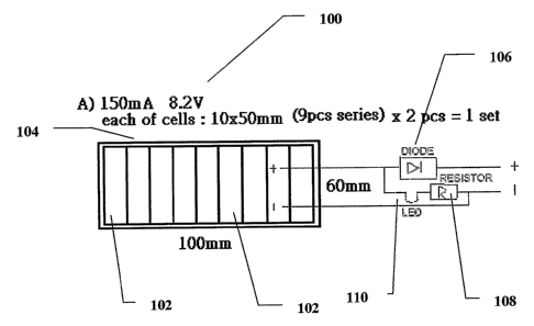
made to Figure 1, which shows a schematic block diagram of an exemplary solar
cell
(photovoltaic cell) circuit according to the present invention. As shown, a
circuit 100
features a plurality of photovoltaic cells 102 (AEG AG, Germany). In the
exemplary
implementation of circuit 100 shown, nine photovoltaic cells 102, although it
should
be understood that this is for the purposes of discussion only and is without
any
intention of being limiting. The size of each photovoltaic cell 102, and the
number
included in circuit 100, are optionally and preferably determined according to
the
amount of power to be produced. For example, optionally and preferably each
photovoltaic cell 102 may be about lOmm by about SO mm. Circuit 100 would then
be about 100 mm in length and 60 mm in width as shown. Of course, any suitable
size or number of photovoltaic cells 102 and/or circuit 100 may optionally be
used.
For circuit 100 as shown, this implementation would produce about 150 mA and
8.2
V of electrical energy.
Photovoltaic cells 102 preferably feature a busbar 104 as an example of
interconnecting material between photovoltaic cells 102, more preferably as a
grid
between photovoltaic cells 102.
Circuit 100 also preferably features a blocking or bypass diode 106, for
forcing the current to only flow in one direction. Blocking diode 106 is
preferably
connected in series to photovoltaic cells 102 as shown, for protecting
photovoltaic
cells 102 from a reverse power flow, and hence protects photovoltaic cells 102
from
thermal destruction (which could occur if such a reverse power flow would not
be
blocked). Blocking diode 106 may also optionally be implemented as a bypass
diode,
which is connected across one or more photovoltaic cells 102 (not shown) and
which
therefore conducts if the one or more photovoltaic cells 102 become reverse
biased.
The bypass diode may also optionally be connected anti-parallel across a
portion of
the plurality of photovoltaic cells 102, for example to protect photovoltaic
cells 102
from thermal destruction.
Circuit 100 also preferably features a resistor 108 for regulating the level
of
the current and voltage. Optionally and preferably, circuit 100 features a LED
(light
ft
CA 02475100 2004-08-03
WO 03/067669 PCT/IL03/00089
emitting diode) 110 or other light emitting device, for showing to the user
that circuit
100 is capable of providing electrical energy.
Circuit 100 is also preferably connected (through resistor 108) to the device
to
be powered (not shown).
Figure 2 is a schematic block diagram of an exemplary panel according to the
present invention. It should be noted that Figure 2 is highly schematic; of
necessity,
certain components are not depicted, in order to render the relationship
between the
remaining components more clearly. Also, the components are shown in Figure 2
according to their logical relationship, and not necessarily according to
physical
location.
Figure 2 shows a panel 200, featuring a plurality of photovoltaic cells 102,
connected by an interconnecting material such as busbar 104 for example.
Photovoltaic cells 102 are preferably mounted on a substrate 202, optionally
with a
glue or other adhesive substance. Busbar 104 is also preferably mounted on
substrate
202, also optionally with a glue or other adhesive substance.
As previously described, each of photovoltaic cells 102, busbar 104 and
substrate 202 is preferably constructed of a substantially absorbent, and/or
anti-
reflective and/or anti-scattering material, which also preferably features low
emissivity as previously described. For example, photovoltaic cells 102 are
optionally and more preferably at least covered with oxidized chrome, also
known as
"black chrome". Photovoltaic cells 102 may optionally be purchased with the
black
chrome (black anti-reflective coating) material already present. Busbar 104
also
comprises an electrically conductive material. Optionally and preferably,
these two
characteristics are present in a single material and/or amalgamate and/or
composition,
such as carbon for example. Carbon (graphite) may optionally be used, as this
material is electrically conductive. Alternatively, busbar 104 may optionally
be
coated with a coating material that is absorbent and/or anti-reflective and/or
anti-
scattering.
According to the present invention, the combination of these different types
of
optional but preferred materials comprises an example of "black on black"
solar panel
technology according to the present invention.
Panel 200 also preferably features an electrical connecting component 204,
which optionally and more preferably features the resistor and blocking and/or
bypass
diode of Figure 1 (not shown), and optionally and most preferably features the
LED of
!~
CA 02475100 2004-08-03
WO 03/067669 PCT/IL03/00089
Figure 1 (not shown). Electrical connecting component 204 also preferably
features a
universal connector 206, which is preferably capable of connecting to a
specific
connecting component 208. Specific connecting component 208 preferably
features
one end that is capable of connecting to universal connector 206, and another
end that
is capable of connectably providing power to the device to be powered (not
shown).
Figure 3 is a schematic block diagram of an exemplary system according to
the present invention. Again, it should be noted that Figure 3 is highly
schematic; of
necessity, certain components are not depicted, in order to render the
relationship
between the remaining components more clearly. Also, the components are shown
in
Figure 3 according to their logical relationship, and not necessarily
according to
physical location.
Figure 3 shows a system 300, featuring panel 200 of Figure 2. Panel 200 is
optionally and preferably connected to a control panel 302. As shown, a
plurality of
panels 200 is preferably connected to control panel 302. Control panel 302
1 f preferably electrically connects and disconnects components of system 300.
According to a preferred embodiment of the invention, control panel 302
preferably
includes at least one, and more preferably a plurality of voltage regulators
304 as
shown. A battery 308 may optionally be connected to the device to be powered
(not
shown), and is typically part of the device to be powered. An AC circuit may
optionally be present between battery 308 and panel 200.
Control panel 302 may also optionally and preferably feature a transfer
apparatus 322 for transferring electric power from photovoltaic cells 102 to
any
electrically powered device (not shown) when battery 308 is fully charged, for
example by using a multiple plug device (not shown). An additional battery 316
may
optionally be used as a buffer battery, for example if there is not suiEcient
light to
power the device to receive power, and/or to start charging. Battery 316
preferably is
rechargeable, so as to be able act as a small reservoir of power. Such an
implementation is particularly preferred when a significant amount of power is
required, for example for a laptop or other device, and/or as a back-up power
source,
and/or in a situation in which suiEcient light is not available. Preferably,
battery 316
is adapted to be held within a holder for holding the device to be charged
(not shown).
Battery 308 may optionally be implemented as a plurality of batteries in a
battery bank for any of the above configurations.
t3
CA 02475100 2004-08-03
WO 03/067669 PCT/IL03/00089
Figure 4 shows a photograph of panel 200 according to the present invention.
Photovoltaic cells 102 and busbar 104 are clearly visible, as is substrate
202. A
portion of substrate 202 may optionally serve as a handle 400.
Figures 5 and 6 show illustrative, non-limiting examples of holders according
S to the present invention, for operation with an electronic device.
Figures SA and SB show a photograph of an exemplary holder 500 for holding
and providing power to a cellular telephone, PDA or other such handheld and/or
portable device. It should be noted that holder S00 does not need to hold the
device to
be charged during operation, and actually preferably does not hold the device
to be
charged during operation. Holder 500 features panel 200 as shown in Figure SA.
Figure SB shows the back (other side) of holder 500, showing an optional
carrying
clip 502.
Figure 6 shows another holder 600, which contains two panels 200 inside;
when holder 600 is closed, panels 200 are protected but also cannot receive
light.
Opening holder 600, as shown with regard to Figure 6, enables panels 200 to
receive
light and to provide power.
It will be appreciated that the above descriptions are intended only to serve
as
examples, and that many other embodiments are possible within the spirit and
the
scope of the present invention.