Note: Descriptions are shown in the official language in which they were submitted.
CA 02475169 2004-08-04
WO 03/068305 PCT/DK03/00087
1
Infusion device with needle shield
FIELD OF THE INVENTION
The invention relates generally to devices for delivering a selected medica-
tion or another therapeutic fluid to a patient at a subcutaneous or other infu-
sion site. More particularly, the invention relates to a medication infusion
set
of the type having a flexible cannula adapted for subcutaneous placement, in
combination with an insertion, or puncturing, device comprising an insertion
needle extending through the cannula and beyond the outer tip thereof, the
insertion device further comprising a shield adapted to cover the insertion
needle when the latter is withdrawn from the cannula,
BACKGROUND OF THE INVENTION
l5
Medication injection or infusion sets are generally well known in the art, to
include a relatively soft and flexible cannula providing a transcutaneous
pathway through which a selected medication or other therapeutic fluid can
be administered to a patient at a selected subcutaneous site. In a common
form, the soft cannula is carried by a housing initially assembled with an in-
sertion needle extending through the cannula, wherein the insertion needle is
manipulated to pierce the patient's skin to place the cannula transcutane-
ously, followed by withdrawal of the insertion needle to leave the soft
cannula
in place on the patient. In order to allow the insertion needle to be handled,
the needle is normally provided as an insertion device comprising a hub to
which the needle is attached.
The selected medication may then be coupled to the cannula, typically by
means of a length of infusion tubing connected to a medication source, to
deliver the medication through the cannula to the patient.
In one configuration, the infusion tubing is connected to the cannula housing
corresponding to the opening through which the insertion needle has been
CA 02475169 2004-08-04
WO 03/068305 PCT/DK03/00087
2
withdrawn from the cannula, i.e. the tubing is arranged axially with respect
to
the general axial orientation of the cannula. An example of this type of infu-
sion device is disclosed in US patent 6 056 718.
In a second configuration, the infusion tubing is connected to the cannula
housing at a location different from the opening through which the insertion
needle is inserted into the cannula, this configuration allowing the tubing to
be pre-connected to the housing. An example of this type of infusion device
is known from WO 00/03757 and US patent 5 545 143 both disclosing a de-
vice in which the cannula and insertion needle are arranged perpendicular to
tubing. In order to seal the device, a self-sealing penetratable septum is pro-
vided corresponding to the opening through which the insertion needle is
withdrawn, this septum also allowing samples to be taken without having to
disconnect the tubing.
The use of insertion needles, or needle devices in general, is associated with
some disadvantages during use thereof due to the potential danger of expo-
sure to the pointed tip before use as well as after the needle has been with-
drawn and before it has been properly discarded. Correspondingly, a large
number of needle protection devices have been proposed to provide a rem-
edy to this problem.
A very simple form of protection is the traditional tubular sleeve which nor-
mally covers the needle when supplied to the user, for example as shown in
US patent 5 545 143; after use the cover may be used to cover the needle
again, however, in most cases the needle and the cover are discarded sepa-
rately. A more elaborate shell-shaped needle guard is disclosed in US patent
6 056 718, however, basically this guard functions as a simple needle cover
to be removed from the insertion device prior to use.
In order to better protect against unintended needle prick, a number of shield
devices has been proposed based on the principle that a pivotable shield is
mounted corresponding to the front of the device, this allowing the shield to
CA 02475169 2004-08-04
WO 03/068305 PCT/DK03/00087
3
be pivoted away before use of the needle as well as used to cover the needle
immediately after use. An example of this type of needle protection device is
disclosed in US patent 5 011 475.
For the above-described type of infusion devices in which an insertion needle
is arranged through a cannula, different solutions have been proposed. For
example, a recent type of needle protection devices is based upon the princi-
ple that a protecting means automatically grips the needle tip as the
insertion
needle is withdrawn from the infusion device, however, this solution requires
a separate cover to protect the needle prior to use,
A different approach is known from WO 00/03757 disclosing an infusion de-
vice in which an insertion needle hub is provided with a hinged shield mem-
ber protruding there from, whereby the shield member is adapted to pivot and
thereby cover the insertion needle when withdrawn from the infusion device.
Also this solution requires a separate cover to protect the needle prior to
use.
SUMMARY OF THE INVENTION
Having regard to the above discussion of the prior art, the object of the pre-
sent invention is to provide an infusion device comprising a hollow cannula
and having an insertion needle arranged there through, in which shielding
means is incorporated providing a user with a high degree of protection
against injury from unintended needle prick during operation and handling of
the device yet providing ease of use as well as allowing the device to be
manufactured in a simple and cost effective manner.
The present invention is based on the realisation that an infusion device of
the above type having an insertion needle arranged through a cannula can
be provided with a fully integrated needle shield by forming the needle with
an integrated shield which is capable of both covering the cannula with the
needle inserted there through prior to use, as well as covering the needle
when it is withdrawn from the cannula, yet allowing the user to insert the
CA 02475169 2004-08-04
WO 03/068305 PCT/DK03/00087
4
cannula. More specifically, this functionality is achieved by providing a
"bridge" between the hub portion of the insertion device and the shield actu-
ally covering the needle/cannula, this allowing the hitherto separately sup-
plied components to be formed integrally with each other.
Thus, in accordance with the invention, an infusion set comprising an infusion
device and an insertion (puncturing) device is provided, the infusion device
having a housing comprising an opening and a soft cannula extending from
the housing and being in flow communication with the opening, the soft can-
nula having an outer tip, an insertion device adapted to be connected to said
housing, the insertion device comprising a hub and a needle mounted
thereon, the needle being adapted to extend through the cannula and beyond
the outer tip thereof when the insertion device is connected to the housing,
the needle being at the outer end adapted for facilitating puncturing, wherein
a shield member is provided having an initial position in which it covers the
cannula and the protruding outer tip of the needle, a retracted position allow-
ing the cannula to be inserted, and a final position in which the shield
covers
the needle when the insertion device has been removed from the housing.
The final position may be identical with the initial position, or it may be
differ-
ent as in a preferred embodiment in which the needle is bend when the
shield member and the hub is locked together, whereby the bend needle pro-
vides a biasing effect between cooperating locking means on the shield part
and the handle part, and whereby the bend needle closely abuts on the
shield to ensure that unintended contact with the needle is avoided.
In a preferred embodiment the shield member is in the form of a single cover
member extending generally along the axis of the cannula/needle, and being
pivotally connected to the hub allowing it to be pivoted between its different
positions. The pivoting action may be provided by a "traditional" hinge or by
any flexible arrangement allowing the shield member to pivot or deflect rela-
tive to the hub. The shield member may be arranged to pivot corresponding
CA 02475169 2004-08-04
WO 03/068305 PCT/DK03/00087
to any desired axis, e.g. parallelly with or perpendicular to the skin surface
in
a situation of use.
Preferably the different positions are predefined, the housing and/or
insertion
5 device comprising mating coupling means so as to allow the shield member
to lock into its initial, its retracted respectively its final position.
Indeed, the
mating coupling means for the initial and for the retracted positions should
be
adapted for releasably securing the shield in the respective positions,
whereas the mating coupling means for locking the shield to the hub prefera-
bly are non-releasable to prevent reuse of the needle or inadvertent release
of the shield. In case the different positions are not predefined, there may
be
an indefinite number of equivalent positions for each of the "functional" posi-
tions; however, the term "position" when used in the present context covers
any such plurality of functionally equivalent positions.
In a preferred embodiment the housing comprises a resilient self-sealing sep-
tum mounted generally at a proximal end of the cannula for normally closing
the proximal end thereof, the infusion needle being mounted there through in
its initial coupled position.
In a further preferred embodiment the housing comprises a cavity having an
inlet and an outlet, the outlet being ira fluid communication with the
cannula,
the inlet being adapted for receiving the insertion needle and preferably com-
prises a resilient self-sealing septum as described above. The cavity may be
provided with one or more additional openings providing access thereto,
each opening being closed by a self-sealing septum or any other suitable
closure means for sealing the opening when not in use. Indeed, in a simple
configuration, the opening may be formed by the proximal end of the can-
nula.
All of the above features are desirably provided in an infusion set
constructed
from relatively simple and preferably disposable components which can be
CA 02475169 2010-12-09
65684-99
6
manufactured in a cost-efficient manner from medical grade plastic or the
like, the
needed itself preferably being made from stainless steel.
In accordance with one aspect of this invention there is provided an
infusion set comprising: an infusion device having a housing comprising an
opening and a soft cannula extending from the housing and being in flow
communication with the opening, the soft cannula having an outer tip, an
insertion
device adapted to be releasably connected to the housing, the insertion device
comprising a hub and a needle mounted thereon, the needle being adapted to
extend through the opening and beyond the outer tip of the cannula when the
insertion device is connected to the housing, the needle being at the outer
end
adapted for facilitating puncturing, wherein the insertion device further
comprises
a shield member having a position in which it covers the cannula and the
protruding outer tip of the needle when the insertion device is connected to
the
housing,,a position allowing the cannula to be inserted when the insertion
device
is connected to the housing, and a final position in which the shield member
covers the needle and the outer tip thereof when the insertion device has been
removed from the housing, characterized in the shield member and the hub
including cooperating locking means for holding the shield member in said
final
position, said shield member being connected to the hub such that the needle
is
bent in said final position, said bent needle providing a biasing effect
between said
cooperating locking means, the bent needle closely abutting on the shield
member.
BRIEF DESCRIPTION OF THE DRAWINGS
In the following the invention will be further described with
references to the drawings, wherein
fig. 1 shows a three-dimensional representation of an infusion set in
an initial position comprising an infusion device and an insertion device in
accordance with the invention,
fig. 2A shows a longitudinal cross-sectional view of the set shown in
fig. 1,
CA 02475169 2010-12-09
65684-99
6a
fig. 2B shows a transverse cross-sectional view of the set shown in
fig. 1,
fig. 3 shows a longitudinal cross-sectional view of the insertion
device shown in fig. 1,
fig. 4A shows a three-dimensional representation of the infusion set
of fig. 1 with a shield member in a retracted position,
fig. 4B shows the infusion set of fig. 4A in a side view,
fig. 5A shows a three-dimensional representation of the insertion
device of fig. 3 with the shield member in a final position,
fig. 5B shows the insertion device of fig. 5A in a side view,
fig. 5C shows a longitudinal cross-sectional view of the insertion
device of fig. 5A,
CA 02475169 2004-08-04
WO 03/068305 PCT/DK03/00087
7
fig. 6 shows a schematic representation of a further embodiment an infusion
set in an initial position,
fig. 7 shows the infusion set of fig. 6 with the shield member in a retracted
position, and
fig. 8 shows the insertion device of fig. 6 with the shield member in a final
position
to DESCRIPTION OF THE PREFERRED EMBODIMENTS
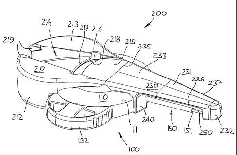
Fig. 1 shows a preferred embodiment of the invention comprising two individ-
ual components, an infusion device 100 comprising a housing 110 and a
cannula 150, and an insertion device 200 releasably coupled thereto and
comprising a hub 210 and a hollow needle 250 mounted thereon, the needle
being adapted to extend through the cannula and beyond the outer tip
thereof when the insertion device as shown is connected to the housing, the
insertion device further comprising a shield member 230 for shielding the tip
of the needle. In the shown embodiment the housing comprises a cap 132
arranged in an inlet opening in the housing (to be explained in greater detail
below).
The housing 110 generally has a disc-formed, circular configuration (see figs.
2A and 2B) defining an upper surface 111, a lower surface 112 defining a
general plane for the housing as well as for the infusion set in general, a
front
end and a rear end, and has a central bore formed there through, the bore
having a rear portion forming a cavity 115 with an opening 113 and a front
portion 116 of reduced diameter. In the following these orientations will gen-
erally be used for all components and structures.
The cannula 150 comprises a straight tubular main portion 152 forming the
cannula per se and having an outer tip 151 with a distal opening, and a rear
portion 153 adapted to be sealingly received and mounted coaxially in the
CA 02475169 2004-08-04
WO 03/068305 PCT/DK03/00087
8
front-most portion of the bore, thereby defining an outlet from the cavity. In
the rear-most portion of the cavity a resilient self-sealing septum 120 is
mounted generally axially in respect of the cannula and defining an inlet for
the cavity, this allowing an infusion needle to be mounted through the septum
and out through the cannula. As appears, the cannula and the central bore
are arranged slightly inclined with respect to the general plane of the hous-
ing, this for facilitating mounting of the infusion device on the skin surface
of
a user.
10, In the shown embodiment the housing comprises a further bore 130 in com-
munication with the central bore and arranged perpendicularly thereto, the
further bore comprising a further resilient self-sealing septum 131 defining a
further inlet for the cavity, the septum being protected by a releasably
mounted semi-circular cap 132, however, in order to allow a standard tube
connector to be connected, the septum may be dispensed with. Optionally
the housing may be provided with a peripheral cover member 118 to improve
grip and appearance.
The hub 210 comprises a mounting portion 211 to which the needle 250 is
fixedly mounted, two laterally arranged handle portions 212, 213 providing
gripping surfaces for handling the device, an upwardly open groove 214 be-
ing defined therebetween and extending coaxially with the needle, and a for-
wardly protruding "bridge" portion 215 extending as a continuation of the
groove. As appears, a transverse slot or opening 216 having front and rear
edges 217, 218 is provided in the bridge portion as well as coupling means
219 is associated with groove, the importance of which will be described in
detail below.
The shield member comprises a generally flat roof-like cover portion 231 hav-
ing lateral edges 236, 237 and a rounded nose portion 232 at the distal end
thereof adapted to substantially surround the pointed needle tip 251, and a
rearwardly protruding "bridge" portion 233 pivotably attached to the bridge
portion of the hub, thereby defining a hinge 235 which in the shown embodi-
CA 02475169 2004-08-04
WO 03/068305 PCT/DK03/00087
9
ment is in the form of a film-hinge. As appears, the bridge portions span
across the upper surface of the housing thereby connecting the hub with the
shield member. Indeed, functionally the bridge may be formed as a single
portion, the hinge being arranged corresponding to a rear or front portion of
the housing, or it may be provided by lateral members arranged along the
sides of the housing, or in any other suitable way.
Protruding downwardly from the proximal portion of the cover are arranged
coupling arms 240 formed with coupling means adapted to engage corre-
sponding mating coupling means on the housing. The coupling means may
be in the form of distal hook members arranged on the arms gripping edge
portions on the housing, or the arms may be slightly inwardly curved as
shown. In fig. 3 the insertion device is shown detached from the housing.
In figs. 1, 2A and 2B the infusion set is shown in its initial state as
supplied to
the user, i.e. with the needle mounted through the cavity and with the pointed
tip protruding from the distal opening of the cannula, and with the shield
member arranged generally coaxially with the cannula/needle, the nose por-
tion 232 substantially surrounding the needle tip. Due to the coupling arms
240, the shield member as well as the insertion device as such is locked in
place to the housing.
Next, use of the device in accordance with the invention will be described. In
order to insert the cannula with the needle arranged there through, the shield
member 230 is pivoted upwardly and backwardly approximately 180 degrees
as shown in figs. 4A and 4B, thereby positioning the shield member in the
retracted position allowing the cannula to be inserted. In the shown embodi-
ment the shield member is positioned and locked in place in the groove 214
formed in the hub, the coupling means 219 associated with groove gripping
the lateral edges 236, 237 of the shield thereby holding it releasably in
place,
this providing for improved handling during the insertion procedures.
CA 02475169 2004-08-04
WO 03/068305 PCT/DK03/00087
In the shown embodiment no special locking means is provided between the
hub and the housing, the components being coupled to each by the frictional
engagement between the needle and the septum respectively the inside of
the cannula. In case the resistance to penetration by the needle is high, the
5 user will grip the infusion set to gently press the components together
corre-
sponding to the longitudinal axis of the cannula. If deemed necessary, a re-
leasable locking means may be provided between the hub and the housing.
In order to indicate that the needle tip has been positioned in a blood
vessel,
10 the proximal end of the needle may be in fluid communication with a venti-
lated so-called flash chamber (not shown) which is adapted to be filled with
blood, a transparent window allowing this to be observed by the user. Indeed,
in case the cannula is intended for being placed at a selected subcutaneous
site, such a chamber would not be relevant.
When the needle tip has been positioned properly, e.g. at a selected subcu-
taneous site or in a blood vessel, the insertion device and thus the needle is
retracted from the cannula and the housing. The lower surface of the housing
may be provided with an adhesive allowing it to be attached to the skin sur-
face of the user, or it may be held in place by additional adhesive means.
After this, a fluid source may be connected to any of the fluid inlets to the
cavity for supplying a fluid out through the cannula.
When the insertion device has been withdrawn from the infusion device, the
shield member is disengaged from the groove and pivoted to a final position
at least covering the needle. In the shown embodiment the shield member is
pivoted further downwardly and subsequently upwardly until engagement
with a lower surface of the hub thereby bending the needle as shown in figs.
5A-5C. As appears, the shield member is thereby pivoted approximately 315
degrees (7/8 of a full turn) from the retracted position to the final
position. In
order to properly secure the shield member in its final position, the coupling
arms 240 are formed with coupling means adapted to engage corresponding
mating coupling means associated with the slot 216 when placed there
CA 02475169 2004-08-04
WO 03/068305 PCT/DK03/00087
11
through. The coupling means may be in the form of distal hook members on
the arms adapted to engage a sharp edge on the front edge 218, or the arms
may be gripped by both of the front and rear edge 217, 218. As appears, by
this arrangement the coupling means on the shield member may be used
with corresponding coupling means on both the housing and the hub. To pre-
vent inadvertent release of the shield, the coupling means between the shield
member and the hub should to a high degree be "non-releasable", i.e. to
function as locking means.
As the needle is bend when the shield member and the hub is locked to-
gether, the bend needle provides a biasing effect between the locking means
and assures that the bend needle closely abuts on the shield to further en-
sure that unintended contact with the needle is avoided.
With reference to figs. 6-8 a second preferred embodiment will be described,
the second embodiment generally having a configuration corresponding to
the first embodiment.
More specifically, fig. 6 shows an infusion set comprising two individual com-
ponents, an infusion device 300 comprising a disc formed housing 310 (de-
fining a general plane for the infusion set) and a cannula 350, and an inser-
tion device 400 releasably coupled thereto and comprising a hub 410 and a
hollow needle 450 mounted thereon, the needle being adapted to extend
through the cannula and beyond the outer tip thereof when the insertion de-
vice as shown is connected to the housing, the insertion device further com-
prising a shield member 430 for shielding the tip of the needle. Whereas the
first embodiment was provided with a hinge 235 allowing the shield member
to pivot corresponding to a "well-defined" axis parallel with the general
plane
of the infusion device, the second embodiment is provided with a flexible
hinge member 435 in the form of a zigzag portion allowing the shield member,
to deflect to either side, i.e. in the general plane of the infusion device.
Mating
coupling means are provided on the shield member respectively the hub for
releasably locking the shield member in the retracted position, respectively
CA 02475169 2004-08-04
WO 03/068305 PCT/DK03/00087
12
for locking the shield member in the final position in which the shield covers
the needle when the insertion device has been removed from the housing.
Next, use of the device corresponding to the second embodiment will be de-
s scribed. In order to insert the cannula with the needle arranged there
through, the shield member 430 is pivoted backwardly towards the hub 410
approximately 160 degrees as shown in fig. 7, thereby positioning the shield
member in the retracted position allowing the cannula to be inserted, see fig.
7. As appears, the shield member pivots corresponding to a first hinge mem-
ber 436 of the zigzag portion. As shown, the shield member is positioned and
locked in place along a side portion of the hub by a flange 431 being gripped
by a corresponding slot (not shown) in the hub thereby holding it releasably
in place, this providing for improved handling during the insertion
procedures.
After the cannula has been placed, the insertion device is withdrawn from the
infusion device and the shield member is disengaged from the hub and "piv-
oted" to a final position covering the needle, see fig. 8. As appears, the
shield
member first pivots corresponding to the first hinge member 436 of the zig-
zag portion and thereafter corresponding to a second hinge member 437,
whereby the shield member is "pivoted" approximately 7/8 of a full turn from
the retracted position to the final position. Indeed, in a factual situation
of use,
both hinge members will participate when the shield member is pivoted to
either side. In order to properly secure the shield member in its final
position,
the hub is formed with coupling means 411 adapted to engage corresponding
mating coupling means (not shown) on the shield member. To prevent inad-
vertent release of the shield, the coupling means between the shield member
and the hub should to a high degree be "non-releasable", i.e. to function as
locking means.
As in the first embodiment, the needle is bend when the shield member and
the hub is locked together, the bend needle providing a biasing effect be-
tween the locking means.
CA 02475169 2004-08-04
WO 03/068305 PCT/DK03/00087
13
While the present invention has been described in connection with the pre-
ferred embodiment shown in the various figures, it is to be understood that
other similar embodiments may be used or modifications and additions may
be made to the described embodiment for performing the same function of
the present invention without deviating there from. For example, the shield
may be provided by two or more members connected to each other, just as
the means allowing the shield member to move between the different posi-
tions relative to the hub may be provided by e.g. a telescoping arrangement
instead of one or more hinges.
lo Therefore, the present invention should not be limited to any single embodi-
ment, but rather construed in accordance with the appended claims.