Note: Descriptions are shown in the official language in which they were submitted.
CA 02476307 2004-08-16
1
BIOINFORMATION DETECTOR. UTILIZING
CHANGES IN AIR PRESSURE
Technical Field
(0001]
This invention relates to a device for -detection of bioinformation,
and particularly to such a device relying on changes in pneumatic pressure
under the biological load for bioinformation detection. More particularly,
the invention pertains to a device including a hollow, open-top pedestal,
complete with a load-sensing cap, in which there is mounted a strain sensor
for sensing changes in pneumatic pressure due to the biological load ex-
erted via a leg of a bed, chair, or the like on the load-sensing cap. The
term "strain sensor" should be construed to mean any device capable of
sensing strain, as by generating a voltage or varying in electrical
resistance,
examples being a piezoelectric element, strain gage, and semiconductor
sensor.
(0002]
The usual conventional practice for measurement of biological pa-
rameters such as pulsation, breathings, and bodily movements has been to
affix electrodes or probes to the humans or animals. The signals picked
up by these devices are sent over cables or cords to the associated instru-
ments for measurement or observation.
[0003]
This conventional practice is objectionable in that the electrodes or
probes are easy to be displaced on or detached from the human or animal
bodies while in use, failing to pick up the signals from where they should.
Another objection is that the connecting wires such as cords are susceptible
to breakage under certain circumstances of usage, as at their intersections
or folds under the bedding. The breaking of the connecting wires may
lead to the danger of electrification as when the instrument is powered from
a commercial power supply. What is more, the connecting wires lend
themselves to undesired functioning as antennas, attracting external elec-
2
trOmagnetiC nOlSe.
[000]
There has been a known method of bioinformation measurement
other than the attachment of electrodes or probes to the human or animal
bodies. It employs an air-filled bag or mat laid, for example, under part or
whole of the recumbent human body. Pressure variations created inside
the bag or mat are detected with pressure sensors.
[0005]
Although free from the shortcomings.. of the first recited prior art,
this alternative method possesses the drawback that the air bag or mat must
be much larger than the human body, or two or more bags or mats put to
joint use, in order to allow for some body movements thereon. It is also a
serious demerit of this alternative method that the air bags or mats are
themselves so elastic that they absorb pressure variations thereon. These
devices are therefore unfit far applications where very fine signals must be
handled.
Disclosure of Invention
[0006]
The present invention seeks to accurately detect all the required
bioinformation from both humans and animals as they lie on a bed, chair or
the like, without need for attachment of probes or the like to the bodies or
for provision of outsize air bags or mats.
[0007]
For the attainment of these objects, the present invention proposes a
bioinformation detector having a pedestal and a cap thereon which in com-
bination define an enclosed space accommodating a strain sensor. The
detector is designed to be placed under a leg of a bed, chair or the like,
where the weight of the biological body concentrates. The desired bioin-
formation is collected by detecting changes in the pressure of the enclosed
space by the strain sensor.
CA 02476307 2004-08-16
' 3
CA 02476307 2004-08-16
Brief Description of Drawings
[0008)
Figure 1 is an exploded perspective view of the bioinformation de-
tector embodying the novel concepts o.f this invention;
Figure 2 is an axial section through the bioinformation detector of
Figure I assembled and fitted with electric means;
Figure 3 is a view similar to Figure 3 but showing another preferred
form of bioinformation detector according to the invention; and
Figure 4 is a vertical section through still another preferred form of
bioinformation detector incorporating a plurality of detector units each
constructed ass in Figures 1 and 2.
Best Mode for Carrying Out the Invention
[0009)
The mechanical organization of the bioinfonmation detector ac-
cording to the invention will be apparent from a study of Figure 1, from
which electrical parts have been omitted for simplicity. The reference
numeral 1 in this figure generally denotes a pedestal in the shape of an up-
standing, hollow, open-top cylinder, complete with three annular steps I1,
12 and 13 to provide three coaxial cylindrical parts which diminish in di-
ameter from the bottom upwards.
[OOIO)
The pedestal 1 defines a cavity 14 extending coaxially from the top
of the pedestal and terminating short of its bottom. Although shown to be
cylindrical in shape, the cavity 14 could be of various other shapes as long
as they do not run counter to the constructional and operational features of
the bioinformation detector hereinafter set forth.
[0011 )
The pedestal 1 is furnished with means 1 S for adjustment of static
air pressure in the cavity 14. The pressure adjustment means I S include
an air passageway extending radially of the pedestal 1 to communicate the
cavity 14 with atmosphere. The air passageway is equipped with valve
means for placing the cavity 14 in and out of communication with atmos-
phere as well as for permitting controlled airflow through the passageway
4
CA 02476307 2004-08-16
for optimum static pressure.
[0012]
At 2 in Figure I is seen a sealing ring of elastic material with a cir-
cular cross-sectional shape. The sealing ring 2 has an inside diameter
approximately equal to the inside diameter of the pedestal step 12, and an
outside diameter approximately equal to its outside diameter. The sealing
ring 2 can therefore fit over the step 13 so as to rest on the step 12.
[0013]
Shown also in Figure 1 is a cap 3 having a cavity 31 extending up-
wardly from its bottom and terminating short of its top. The cap cavity 3 I
has a diameter somewhat greater than the outside diameter of the pedestal
step 12. The cap 3 is also provided with an air passageway and associated
valve means 32 for placing the cap cavity 31 in and out of communication
with atmosphere, with a capability of permitting airflow through the pas-
sageway at a controlled rate for optimization of static air pressure in the
cap
cavity.
[0014]
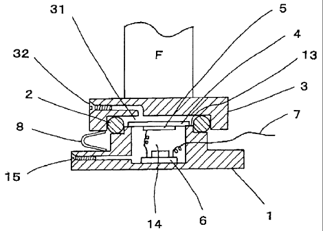
Figure 2 depicts the pedestal 1, sealing ring 2, and cap 3 of Figure 1
assembled together with some additional means to provide the bioinforma-
tion detector according to the invention. The pedestal 1 has its open top
closed by a diaphragm 4 which has its peripheral marginal edge affixed to
the step 13. A strain sensor 5 is attached to the underside of the dia-
phragm 14 and electrically connected to a circuit board 6 on the bottom of
the pedestal cavity 14. The circuit board b is furnished with means for
amplifying the signal generated by the strain sensor 6, preparatory to deliv-
ery to external circuitry, not shown, by way of a cable or cord '7. Wireless
sensor signal transmission is of course possible by incorporating a power
supply and transmitter with the circuit board 6.
[0015]
A conductor or conductors 8 are installed between pedestal I and
cap 3 for electrostatically shielding the pedestal cavity 14 and cap cavity 3
i .
Preferably, the conductors 8 may be made from resilient material in order
to add to resiliency between pedestal 1 and cap 3.
[0016)
When a leg F of a bed or chair is placed on this bioinformation de-
tector as in Figure 2, the sealing ring 2 will yield to the weight exerted
5
thereon via the cap 3, thereby hermetically sealing the joint between ped-
estal 1 and cap 3 and hence the cap cavity 3 I above the diaphragm 4. The
physical vibration transmitted from the human or other biological entity on
the bed or bed to the cap 3 will cause pressure variations in the hermeti-
cally closed space. The strain sensor 5 will translate the resulting strain of
the diaphragm 4 into a voltage signal. Received and amplif ed by the
electronic circuit on the circuit board 6, the sensor output signal will be de-
livered over the cable 7 to the unshown external means for measurement or
observation.
[0017]
The static air pressures in the pedestal cavity I4 and cap cavity 31
may be independently adjusted and optimized as aforesaid by the pressure
adjustment means I 5 and 32. Fox instance, if the load weight from the leg
F is found excessive, the adjustment means 32 on the cap 3 may be opened
to permit air escape from the cap cavity 3 until the pressure drops to a de-
sired degree. The pressure in the pedestal chamber 14 may be made equal
to the atmospheric pressure by opening the pressure adjustment means I S if
the load weight is too light.
Eoolg]
Notwithstanding the showing of Figure 2, and as will have been
understood from the foregoing, the bioinformation detector according to
the invention need not necessarily be positioned in use with the cap 3
directed upward. It will indeed function just as dell if placed upside
down, with the leg F loaded on the pedestal 1. Desired bioinformation
will be obtained equally well if the device is positioned either way.
(0019]
Another preferred embodiment of the invention is shown in Figure
3, in which parts corresponding to those in Figures 2 and 3 are identified by
like reference characters. This second embodiment includes the pedestal
I with a modified cavity 14 having a constriction 16 open to the cap cavity
31. The other end, at the bottom of the pedestal I, is open but is closed as
the pedestal 1 is positioned on the floor 17.
(0020]
The constriction 16 makes it unnecessary to close the open top of
the pedestal cavity 14 with a diaphragm as in the previous embodiment; in-
stead, the strain sensor 5 is mounted directly to the top of the pedestal 1 so
CA 02476307 2004-08-16
6
CA 02476307 2004-08-16
as to close the constriction 16 of the pedestal cavity 14.
(0021 ]
Thus the pressure variations caused in the cap cavity 31 will be ap-
plied directly to the strain sensor 6 via the constriction 16 thereby
straining
the strain sensor 6 and so causing the latter to develop a proportional volt-
age signal. The voltage signal will be amplified by the unshown amplifier
on the circuit board 6, which is shown mounted to the outside of the pedes-
tal 1, preparatory to delivery to the external equipment for measurement or
observation. As in the previous embodiment, such signal delivery to the
external equipment may be made without use of wires, by incorporating a
battery and transmitter with the circuit board 6. The pressure adjustment
means 15 and 32 are of the same construction and operation as their coun-
terparts of the foregoing embodiment.
(0022]
Two or more bioinformation detectors according to the invention,
each constructed as in Figure 2 or 3, may be put to combined use as in Fig-
ure 4. Desired bioinfonnation will be obtained satisfactorily if only one
device of the Figure 2 or 3 construction is placed under one of the four legs
of a bed or chair. Actually, however, such devices will have to be placed
under all the legs because the bed or chair would slant or become rickety if
only one is installed under one of its legs. It must also be taken into con-
sideration that the weight of the object of measurement will be distributed
over large areas if it lies on something that has no legs or like downward
projections, such as a toilet seat, bathtub, or flooring. The embodiment of
Figure 4 is well adapted for such applications.
(0023]
The part of the composite apparatus shown encircled in Figure 4 is
of exactly the same construction as the bioinformation detector of Figure 2
except that the pressure adjustment means 15 and 32 are not shown for
simplicity. The caps of all the individual detector units of Figure 4 are in-
tegrally combined into what may be termed a platform 33. This platform
is subject to change in both shape and size depending upon what is to be
placed thereon, for example, a bed, chair, toilet seat, and so forth. The
subject of measurement may lie directly on the platform 33, either
recumbently or otherwise.
CA 02476307 2004-08-16
[0024]
As has been mentioned in connection with Figure 2, the individual
detector units of Figure 4 could be positioned upside down. In that case
the pedestals l, instead of the caps 3, of all the detector units might be com-
bined into one platform.
Industrial Applicability
(0025]
The bioinformation detector according to the invention is applicable
to medical and healthcare fields, by being compactly attached to the legs of
beds or chairs, toilet seats, or floorings for accurately capturing
information
from the biological objects resting thereon.