Note: Descriptions are shown in the official language in which they were submitted.
CA 02476932 2004-08-18
WO 03/084320 PCT/US03/09362
METHOD AND APPARATUS FOR AUTOMATIC PEST TRAP REPORT GENERATION AND FOR
RECORDING ADDITIONAL TRAP PARAMETER DATA
Field of the Invention
This invention relates generally to a method and apparatus for
providing reporting on a plurality of activity sensing pest devices; more
particularly
to a system for providing automatic reporting from a plurality of activity
sensing pest
devices together with physical inspection data; and still more particularly to
an
automatic real-time reporting system for a plurality of traps with manual
input means
for providing additional data on trap parameters based on physical inspection
and a
report generation means on the resulting combined data.
Background
Rodents, flies, cockroaches, and other nuisance insects and animals
(hereafter referred to collectively as "pests") create health concerns and
introduce
spoilage, among other concerns. Many businesses deploy a variety of traps
and/or
monitors throughout the business' physical premises and facilities to insure a
reduction and/or elimination of such pests. These actions can be undertaken to
insure inspection compliance, to maintain sanitary conditions, reduce
spoilage,
comply with applicable laws and regulations, and/or increase consumer
confidence.
Even upon complete elimination of pests from a physical site, however, the
pests can
often find their way back into the premises. For example, open doors, windows
or
loading docks, cracks in foundations, delivery of contaminated materials or
packaging, etc., may all provide an avenue for access back into the premises.
Therefore, even if the pests are reduced or eliminated, pest traps are
continuously
used in order to detect the presence of pest activity.
Since many physical plants are large, often a great many traps are
required to adequately cover the premises. As the number of traps increases,
so too
does the time and labor required to physically inspect the traps. Presently,
physical
inspections of each and every trap at a facility are performed at desired time
intervals
(e.g., weekly or monthly). These inspections insure that captured pests are
removed
1
CA 02476932 2004-08-18
WO 03/084320 PCT/US03/09362
from the trap, that the trap is in working order and that the trap is still in
the proper
location. It will be appreciated, however, that while each trap is inspected,
such
inspection is not oftentimes needed for each trap. For example, in many cases
a
large number of traps did not catch any pests in the given time interval, the
traps are
still in working order and the traps are properly placed.
In the prior art, systems have been developed (such as U.S. Pat. Nos.
4,517,557; 4,884,064; and 5,949,636) which are focused principally on
notification
of trap activity. These same devices suffer from drawbacks in that they do not
provide additional information regarding the time of activity, the condition
of the
trap and the ability to track other parameters which may help reduce the pests
on a
more constant basis on the premises.
For example these prior art systems do not have the ability to
reconcile different modes of trap activity, such as human or environmental
interference with actual pest activity. A pest control system can preferably
differentiate pest and non-pest activity in order to use information to
identify and
address the source of pest activity. An additional drawback of systems in the
prior
art is the lack of ability to track the action(s) taken once trap activity
occurred. Such
actions may include the trap being inspected and emptied, if required, as well
as the
time between trapping a pest and removing it from the facility.
Pest information systems utilizing barcode scanning and manual data
input are also known in the art. These systems (such as the barcoding system
sold
under the designation Estat by the assignee of the present invention, Ecolab
Corporation, as part of its Ecopro system) do not quantitatively track pest
activity as
a function of desired time intervals (e.g., such as daily, hourly, etc.).
Additionally,
the prior art barcode scanning systems do not provide data or otherwise
indicate
potential trap activity prior to actually visiting the trap.
A combination of activity sensing pest devices equipped with
feedback mechanisms would significantly improve the ability to deliver pest
control
at a facility. For example by having a more comprehensive understanding of the
conditions which existed when the pest was captured, such conditions may be
altered
so that the opportunities to capture additional pests and/or reduce the re-
introduction
2
CA 02476932 2004-08-18
WO 03/084320 PCT/US03/09362
of pests into the facility are maximized. By taking such proactive steps, the
costs
and labor associated with monitoring the traps may be ultimately reduced.
Therefore, there arises a need for a pest monitoring and reporting
apparatus and method which provides timely reporting on pest conditions and
for the
introduction of additional data from a physical inspection of the pest
monitoring
location. The pest monitoring location can be a passive or active monitoring
location, can include trapping, and/or can include a combination of monitoring
and
trapping. Further, such system would also help reduce unnecessary visits to a
number or percentage of the locations and traps that do not require physical
inspection at that time. The present invention directly addresses and
overcomes the
shortcomings of the prior art.
Summary
The present invention provides for a method, apparatus and reporting
system for collecting, communicating and analyzing information from a
plurality of
pest monitoring locations. The monitored locations include activity sensing
pest
devices. These devices can include traps and/or passive and active monitoring
devices not having a trapping or killing functionality. While traps may
constitute the
majority of activity sensing pest devices in a given pest control program,
devices
which only monitor pest activity may be preferred in some locations and
applications. Accordingly, both types of devices may be utilized in the
various
environments in which the present invention may be employed. Further, unless
the
context provides otherwise, both traps and passive or active pest monitoring
devices
are included within both the scope of the term "activity sensing pest devices"
and
within the scope of the invention.
The system provides automatic reporting from a plurality of activity
sensing pest devices and further includes physical inspection data. The
resulting
reports, due to the additional information, provide a finer granularity report
than was
possible in the prior art. Further, in the preferred embodiment, an automatic
real-
time communication system is used in connection with a plurality of activity
sensing
pest devices. The communication system is preferably radio-frequency (RF) or
other
3
CA 02476932 2004-08-18
WO 03/084320 PCT/US03/09362
over-the-air system. However, hardwired systems, use of a personal digital
assistant
(PDA) as an interim data carrier, and other technologies may also be employed.
Manual input means for providing the additional physical inspection data on
the
activity sensing pest device parameters and a computer based report generation
means (of the resulting combined data) provide for a robust and efficient pest
monitoring and/or trapping tool.
In one preferred embodiment of the present invention, a device
constructed in accordance with the principles of the present invention
includes a
plurality of pest presence sensors located within, adjacent or proximate to a
plurality
of pest traps. As noted above, the sensors may also be used without a trapping
or
killing functionality directly associated therewith. Therefore, the individual
sensors
detect the presence of a pest, detect the presence of a pest in a respective
trap and/or
detect that the trap has operated in a manner indicating the presence of a
pest within
the trap (e.g., that the trap was activated). When the sensor detects this
condition, a
pest signal is generated and a communication device acts to relay the event
data and
a trap identifier code to a computer. The sensor may also provide a time stamp
for
the event data. Alternatively, the computer can generate a time stamp based on
the
time that the signal is received. Since many traps are multiple catch traps,
the
present invention provides for recording and tracking multiple events from a
single
trap. Similarly, pest monitoring devices that do not include a trap often can
provide
information on multiple pest events. The transmitted data is collected in a
database
program running on the computer, and an initial report is generated.
During or subsequent to generating the initial report, a physical
inspection of those traps generating one or more events occurs. The physical
inspection includes resetting traps, identifying false positive trap
conditions,
correcting trap location placement, and identifying other trap parameter data.
Such
data is preferably input at the trap itself via a manual data entry device. It
will be
appreciated, however, that such physical inspection data may also be
temporarily
stored in a portable computer (for example a personal digital assistant (PDA))
and
subsequently downloaded into the computer database. A physical inspection can
also be made of an area in which a monitoring device is located only for pest
4
CA 02476932 2004-08-18
WO 03/084320 PCT/US03/09362
detection and not trapping. Inspection of such areas are preferably made if
such
monitor has generated one or more pest detection signals.
The resulting final report includes pest monitoring data, trap event
data and the physical inspection data. This final report is beneficial to the
pest
control vendor and/or physical location manager since the combination of
location,
time stamp and physical inspection data can lead to determination of pest
infiltration
avenues. Furthermore, by generating an initial report, the physical inspection
may be
modified to visit only those traps or locations generating an event.
Alternatively, a
predetermined number and/or percentage of the other traps at the facility may
also be
visited on a periodic basis to insure that the traps are operable, properly
placed, etc.
Because fewer traps need to be visited on each physical inspection tour, less
time is
spent at the facility by the inspectors. This improves efficiency and cost
effectiveness of the pest control program, while also improving the reporting
function and the proactive nature of the pest control program.
Therefore, according to one aspect of the present invention, there is
provided a pest monitor reporting system, comprising: a pest report
database; a plurality of sensors, the sensors associated with respective
activity sensing pest devices, the sensors being arranged and configured to
determine if a pest is in the area monitored by the sensor and to generate a
pest signal; a communication device, operatively connected to the sensors,
for receiving the pest signal and for communicating to the pest report
database that a pest signal occurred and the specific activity sensing pest
device at which the pest signal occurred, wherein the pest report database is
updated.
According to another aspect of the present invention, there is
provided a pest monitor reporting system as described in the preceding
paragraph wherein the pest activity sensing devices include a pest trap
and/ or include a pest monitor that does not include a trapping function.
According to a further aspect of the invention, there is provided a pest
reporting method for a plurality of activity sensing pest devices (e.g., pest
traps
and/or monitors), comprising: monitoring a plurality of pest presence
signaling
5
CA 02476932 2004-08-18
WO 03/084320 PCT/US03/09362
devices associated with a similar number of pest traps and monitors; recording
the
occurrence of pest presence signals and associating the pest presence signal
with
individual traps and monitors; physically inspecting the pest traps and
monitors
which generate a pest presence signal; determining whether the pest presence
signal
is due to a pest or some other event; and recording additional data based on
the
physical inspection.
Another aspect of the invention includes the method as set forth in the
preceding paragraph and further including one or more of the following
additional
steps:
electronically recording additional data regarding trap condition; physically
inspecting a number of the plurality of traps which did not generate a pest
presence
signal; generating a first report on the traps which generate a pest presence
signal;
and generating a second report which includes the pest presence signal data
and the
additional data.
While the invention will be described with respect to preferred
embodiment configurations and with respect to particular devices used therein,
it
will be understood that the invention is not to be construed as limited in any
manner
by either such configuration or components described herein. Also, while the
particular types of pests and traps are described herein, it will be
understood that
such particular pests and traps are not to be construed in a limiting manner.
Instead,
the principles of this invention extend to any environment in which pest
detection is
desired. Further, while the preferred embodiments of the invention will be
generally
described in relation to transmitting and receiving RF information from the
traps, it
will be understood that the scope of the invention is not to be so limited.
These and
other variations of the invention will become apparent to those skilled in the
art upon
a more detailed description of the invention.
The advantages and features which characterize the invention are
pointed out with particularity in the claims annexed hereto and forming a part
hereof.
For a better understanding of the invention, however, reference should be had
to the
drawings which form a part hereof and to the accompanying descriptive matter,
in
which there is illustrated and described a preferred embodiment of the
invention.
6
CA 02476932 2004-08-18
WO 03/084320 PCT/US03/09362
Brief Description of the Drawings
Referring to the drawings, wherein like numerals represent like parts
throughout the several views:
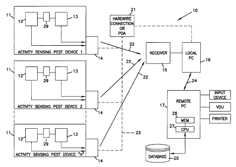
Fig. 1 is a functional block diagram of an automatic pest control
report generation with additional trap parameter data system.
Fig. 2 is a schematic diagram of the report generation process of the
system of Fig. 1.
Fig. 3 is a representative trap location map illustrating the plurality of
pest traps, with the traps including trap identifier codes.
Figs. 4a - 4d are representative reports of the database program for
the traps illustrated in Fig. 3.
Fig. 5a schematically illustrates a functional block diagram of a fly
counter with an optional trapping function constructed in accordance with the
principles of the present invention.
Fig. 5b schematically illustrates a functional diagram of an exposed
elevated side view of the fly trap of Fig. 5a.
Fig. 5c schematically illustrates a functional diagram of an exposed
elevated end view of the fly trap of Fig. 5a.
Fig. 6 schematically illustrates a functional block diagram of a
destructive electrocution insect light trap constructed in accordance with the
principles of the present invention.
Fig. 7a illustrates a perspective view with portions broken away of a
wind-up type rodent trap constructed in accordance with the principles of the
present
invention.
Fig. 7b illustrates a second perspective view with portions broken
away of a wind-up type rodent trap of Fig. 7a.
Fig. 8a illustrates a perspective view of an insect monitor having an
electrode grid (and the cover partially removed) constructed in accordance
with the
principles of the present invention.
7
CA 02476932 2004-08-18
WO 03/084320 PCT/US03/09362
Fig. 8b illustrates a perspective view of the monitor of Fig. 8a with
the cover of the insect monitor in place.
Fig. 8c schematically illustrates a functional block diagram of the
insect monitor of Fig. 8a constructed in accordance with the principles of the
present
invention.
Fig. 9a illustrates a rear view of a Tin-Cat style rodent trap
constructed in accordance with the principles of the present invention.
Fig. 9b illustrates the Tin-Cat style rodent trap of Fig. 9a with the
cover hinged open to reveal the interior of the trap.
Detailed Description
A system constructed in accordance with the principles of the present
invention may be employed in a variety of environments and with a variety of
components. The system may include a variety of styles of activity sensing
pest
devices within a single facility (e.g., for trapping or sensing any type of
animal,
rodent, fly or insect) and utilizing a single reporting database; include
individual
styles of activity sensing pest devices in different reporting databases for
the same
facility; and/or include a single type of activity sensing pest devices in one
or more
reporting databases. In each case, the principles apply to an automatic, real-
time
reporting system for a plurality of activity sensing pest devices (e.g., traps
and/or
pest presence monitors), with manual input means for providing additional data
on
both the pest trap and pest monitor parameters based on physical inspection. A
reporting database collects the data and provides reports on the resulting
combined
data. The system reports have greater utility, improve time, costs and
efficiencies
associated with inspection of the traps, and improves pest control.
A discussion of the various preferred trap and monitor embodiments
which may be used in connection with the present invention will be deferred
pending
a discussion of the functional elements making up the present invention.
First referring to Fig. 1, a functional block diagram of the automatic
pest report generation system and additional pest trap and pest monitor
parameter
data is provided. The system is shown generally by the designation 10. A
plurality
of activity sensing pest devices are shown at the designation 11. Any number
of "n"
8
CA 02476932 2004-08-18
WO 03/084320 PCT/US03/09362
activity sensing pest devices 11 may be utilized in connection with the
present
invention. In the case of traps, each of the n traps 11 include a pest
enclosing,
retaining or killing device (best seen in Figs. 6, 7a-7b, and 9a-9b and
discussed
further below). As discussed above, one or more of the activity sensing pest
devices
11 can also take the form of a passive or active pest monitor -- which monitor
may
or may not include a trapping device (best seen in Figs. 5a -5c and Figs. 8a -
8c). A
pest sensor 12, a physical inspection data entry device 13, and a
communication
block 14 are also provided.
Pest sensor 12 may take a number of forms, but in each form
generally monitors pest activity in and/or about the trap 11. Examples of the
pest
sensor 12 include a switch or mercury switch (for monitoring movement of the
trap),
a capacitance device (for monitoring a pest altering the capacitance of a
grid), a
current monitoring device (for detecting current spikes in a destructive or
electrocution style trap), or light extinction of a light source (for
monitoring an
interrupted beam or laser). The sensor 12 is generally located in or on the
pest trap
11. However, it is possible to also locate the pest sensor 12 adjacent or
proximate
the trap 11. It will be appreciated that sensor 12 may be located in an area
without a
trap being present. In this latter case, the sensor 12 acts as a pest monitor
for that
area. When pest activity is detected and a pest presence or detection signal
is
generated by the sensor 12, the pest presence signal is provided to the
communication block 14.
The communication block 14 may take a number of forms. For
example, the communication block may communicate over a fixed wire (e.g., to
hardwire receiver 21 via optional connection 23) or by telephone or cellular
phone, it
may take advantage of putting signals over existing wiring in a building, or
it may
utilize over-the-air transmissions designated as 22. In each of these forms,
the
communication block 14 operates to pass the pest presence or detection signal -
- as a
pest event -- to a receiver 15 (or alternatively directly to local PC 16). In
the
preferred embodiment, an RF type communication device is utilized. In this
type of
embodiment, the receiver 15 will generally be located relatively close to the
transmitter device in communication block 14. In the preferred embodiment, the
9
CA 02476932 2010-07-20
transmitter range is generally around one hundred feet. However, the range is
affected by,
among other factors, the type of RF device used and by the structural
characteristics of
the facility or area. If appropriate communication schemes are utilized, then
the receiver
15 may be located off-site.
Sensor 12 may include a memory device or other data storage to
accumulate event data and then pass along a block of information to the
communication
device. For example, sensor 12 may be constructed to archive pest presence
signals in an
onboard memory location or in a separate memory device 29. The later
communication
of the stored data may occur at set intervals, and may be prompted by a
polling
transaction, or may be physically activated by an inspector via a personal
computer,
special purpose computing device, or PDA. By storing the data, any number of
pest
detection events may be transmitted as a block.
For example, in one embodiment (best seen in Fig. 5a and discussed in
more detail below) the sensor may archive event data in the counter block 511.
The counter block 511 can include an electronic memory storage location, and
can
optionally include a visually perceptible means for displaying the data such
as an LCD
display or mechanical counter (not shown). The microprocessor block 509 can
initiate
transmission of the collected data via communications block 510. This can take
the form
of a PDA establishing contact with the communications block 510 or take
another of the
forms identified above. The data can be passed as individual event data or as
histograms
of the number of events within different time windows.
The sensor 12 provides data on the activity sensing pest devices 11
identifier code, the time of the event, and the event itself. However, the
receiver 15 or
local computer 16 (discussed below) may provide a date stamp for the received
pest
event. In one embodiment, the communication block 14 includes a transmitter
manufactured by Freshloc Technologies, Inc. (Plano, TX). Such transmitter is a
strobe
radio frequency (RF) transmitter, disclosed in Heller U. S. Pat. No. 5,119,104
and Heller
U. S. Pat. No. 6,222,440. The code of such device may be modified in order to
hold a
resistance change for a period of time to insure that events are detected
during polling.
Once the event is transmitted to receiver 15, the data is provided to
CA 02476932 2004-08-18
WO 03/084320 PCT/US03/09362
local computer 16. Computer 16 may be a special purpose computing device or
may
be a personal computer (e.g., an IBM compatible computer having a Pentium
style
chip). The data is in turn provided to remote personal computer 17 over the
internet
or direct connection 24. Computer 17 includes a processor 27, input devices 18
(e.g., keyboard and mouse or other pointing device), video display unit 19,
and a
printer 20. CPU 27 is provided to run a database program stored in memory 26.
The
program may also be running from a hard drive, floppy drive, CD-ROM, or from a
server or other computer on a network machine. The database 25 is stored in
memory 26. It will be appreciated that the database may also be stored on a
local
area network server, hard drive, cd-rom drive or other storage device
accessible by
the CPU 27.
Database 25 stores the event data and includes other database
functions, such as relating events to pest trap identification numbers, and
generating
reports, among others. In one embodiment, the database program is provided by
FreshLoc Technologies as part of their system identified by as the designation
FreshLoc system. However, other relational database programs capable of
storing
and relating fields in a number of records, and having a report writing
capability may
also be utilized. When utilizing other programs, the received data from the
various
activity sensing pest devices 11 must be recognized by the computer 17 and
stored in
the database 25. The database 25 can reside on local computer 16 with reports
being
generated locally and, optionally, transmitted to other computers via a
network,
extranet or internet.
In the database 25, the activity associated with each activity sensing
pest devices 11 may be tracked by the unique ID number. The facility of
interest
contains any desired number of activity sensing pest devices 11 and the
location of
the activity sensing pest devices 11 are maintained with the unique ID number
to be
used in the reporting process. Fig. 3 illustrates a map of an exemplary
facility with
trap 11 locations and ID's shown. The map data is generated from database 25.
Figs. 4a - 4d identify exemplary reports. An initial report including only
trap
activity data for a specific trap is illustrated in Fig. 4a. It will be
appreciated that
"TRAP ACTIVITY" indicates that the sensor 12 employed in connection with the
11
CA 02476932 2004-08-18
WO 03/084320 PCT/US03/09362
trap generated a pest presence signal which was relayed to the database 25. In
Fig.
4a, the specific trap identified in the report is associated with an
identifier code
"KK6" (best seen in the map of Fig. 3). Virtually any series of letters,
numbers and
symbols might be employed as identifier codes, with the identifier codes set
forth
herein merely being one example. It will also be appreciated that pest
monitors may
be provided with trap ID numbers regardless of whether a physical trap is
associated
with the pest monitor. In Fig. 4b, an initial report is generated showing
traps which
have initiated pest presence signals and other traps which should be visited
according to some schedule. The schedule to visit other traps can be random,
predetermined, or statistically generated. In Fig. 4c, a summary report with
additional trap parameter data added following a physical inspection of the
trap
identified by the trap identification code KK6 is illustrated. In Fig. 4d, a
summary
report for each of the traps identified in Fig. 3 is shown. Figs. 3 and 4a -
4d will be
discussed further below.
In order to provide the feedback information, each activity sensing
pest device 11 also preferably includes one or more feedback devices 13 which
permit an inspector to provide physical trap and monitor parameter feedback at
the
actual location of the activity sensing pest devices 11. This additional data
is
preferably input to the database 25 running on computer 17 (via the
communication
block 14 to receiver 15 to local computer 16). The feedback device 13 may take
the
form of one or more buttons; a keypad; a keyboard; one or more dipswitches; an
infrared receiver which is configured to interact with a PDA (e.g., of the
type sold
under the designation Palm Pilot or other personal data device), or any other
input
device allowing selection among a plurality of parameter ID's such as those
set forth
in Table I below. In each case, the device 13 allows an inspector to indicate
a
particular parameter, from among a predetermined set of parameters. For
example,
an inspector could indicate that a trap was inspected and no animal was found
or that
the trap was inspected and an animal was found. Table I includes a
representative
list of codes which may be utilized by a trap inspector.
12
CA 02476932 2004-08-18
WO 03/084320 PCT/US03/09362
TABLEI
Parameter ID Digital Code Analog Code Parameter
(Voltage level or Description
resistance value
1 0001 V 1 /R1 Trap Checked - No
Activity
2 0010 V2/R2 Trap Checked -
Activity Type 1
Found
3 0011 V3/R3 Trap Checked -
Activity Type 2
Found
4 0100 V4/R4 Trap Checked -
Activity Type 3
Found
0101 V5/R5 Trap Cleaned
6 0110 V6/R6 Trap Out of Place
7 0111 V7/R7 Trap Damaged
8 1000 V8/R8 Light Bulb
Replaced
9 1001 V9/R9 Glueboard Replaced
1010 V 10/R10 Cover Opened
It will be appreciated that the trap parameter/data is exemplary and other
information
5 may be provided. Further, the code number may be assigned arbitrarily. In
other
systems, the code number may be associated with other trap parameters. The
resistance code is provided as an example of values which may be provided to a
FreshLoc type system to distinguish between the various feedback data being
entered. However, various voltage levels (as shown in Table I) may also be
10 employed to generate the feedback data in an analog device.
The feedback data can alternatively be entered directly into local
computer 16 by an operator after physically inspecting the traps. The data
might
also be temporarily stored during the inspection in a PDA or other special
computing
device, and subsequently downloaded into computer 16. In these embodiments, it
will be appreciated that the input block 13, communication block 14 and
receiver
block 15 may be modified to function properly with the data gathering
methodology
employed. However, transmission of initial data on pest activity is preferred
in order
13
CA 02476932 2004-08-18
WO 03/084320 PCT/US03/09362
to generate an initial report (for example visits to the appropriate activity
sensing
pest devices can then be determined).
Preferably each activity sensing pest device 11 includes a feedback
mechanism 13. Due to the characteristics of the physical premises, the costs,
the
benefits from the individual activity sensing pest device 11, and other
factors, one or
more of the activity sensing pest devices 11 may not include a feedback sensor
13.
However, in view of the advantages provided by the feedback reporting system
as
described herein, it will be appreciated that the benefits increase as the
amount and
quality of the feedback data increases.
Once transmitted to the database 25, the additional parameter data on
the activity sensing pest devices is also tracked against the appropriate ID
number.
This results in a refining of both the data and the resulting reports from
database 25.
The activity sensing pest devices reporting becomes a feedback loop as
illustrated in
Fig. 2 by the designation 50. In Fig. 2 the sensors 12 provide data to summing
block
51 and to initial report block 52. The physical inspection component of the
process
includes reviewing the initial report(s) 52 and providing additional physical
inspection data at block 53. The physical inspection data can include data on
each
trap and monitor 11. However, preferably the data is for a smaller set of
traps and
monitors, which include those traps and monitors that generated a pest
activity event
signal and a number or percentage of the remaining traps and monitors of the
"n"
activity sensing pest devices 11 in the facility that did not show any pest
activity.
The feedback loop provides data on false positives, disturbed traps,
and other factors. The time data corresponding to when the pest activity
occurs
helps to proactively determine pest infiltration factors and/or information
relating to
maintaining an optimum pest control plan, such as disturbed traps, etc.
Turning to Fig. 3 and Fig. 4a - d, an example of the system will be
described. In operation, if a mouse was caught in a mousetrap with trap id KK6
(best seen in Fig. 3), the pest event for that trap would be generated and the
date and
time would be communicated to computer 17 for recording to database 25. As
noted
above, an alternative would be to use the clock on computer 16 and/or computer
17
and merely record the date and time of receipt of a transmission from a trap.
A pest
14
CA 02476932 2004-08-18
WO 03/084320 PCT/US03/09362
event may trigger an immediate physical inspection of the trap. However,
generally
such inspections would occur daily, weekly or monthly. An initial report
showing
the pest activity of a particular trap is generated (Fig. 4a) and a plan to
inspect traps
11 showing pest activity is determined (Fig. 4b). In Fig. 4a, the trap
activity is
shown only for trap KK6. Two other traps are shown in Fig. 4b as having trap
activity. These other traps are traps KK1 and KK1 1. These three traps
preferably
have a different color corresponding to the Activity Legend illustrated in
Fig. 3. The
map in Fig. 3 also preferably provides an indication of the number of pest
activity
events received for the given activity sensing pest device.
Fig. 4b also includes a plan to inspect other activity sensing pest
devices 11. Although these latter devices 11 did not show pest activity, an
inspection of the devices can reveal electronics malfunctions, undetected pest
events,
and visual evidence of pest activity that was not detected electronically.
Accordingly, all activity sensing pest devices will generally be inspected
periodically. Such inspections can occur at a Tower frequency based on the
initial
reports. When the trap is physically inspected, feedback on the trap
parameters can
be provided to the system via one or more feedback devices 13. Fig. 4c
illustrates a
summary for a particular trap which generated pest presence signals with
additional
feedback data added to the summary. As shown in Fig. 4c, the trap was
disturbed on
two separate occasions with no rodent caught. This may be an indication of
intentional or inadvertent movement of the trap by workers or inanimate
objects
(e.g., a forklift, pallets, etc.) in the area, a failing trap, or malfunction,
among others.
In any of these events, proactive measures can be taken to determine the cause
of the
activity. Additionally, final summary reports for all of the traps (or a
subset thereof)
can be generated as shown in Fig. 4d.
The various styles of traps 11 may include a large variety of
commercially available traps for trapping any type of animal, such as rodents
or
insects. Examples of commercially available live animal/rodent traps are the
Victor
M3 10 Tin Cat; the Havahart Live Traps; the Kwik Katch Mouse Trap, and the
Kness
Ketch-All. Examples of commercially available zapping light traps are the
Gardner
AG200 1; the Gardner AG-661 Light Trap, and the Anderson Adhesive Insect Light
CA 02476932 2004-08-18
WO 03/084320 PCT/US03/09362
Trap. Examples of commercially available glueboard light traps are the Ecolab
Stealth Unit; the Gardner WS25; the Gardner GT100, and the Anderson Adhesive
Insect Light Traps.
Several preferred embodiments of activity sensing pest devices 11
which may be utilized together with the present invention will next be
discussed.
Figs. 5a through 5c illustrate a non-destructive flying insect monitor,
while Fig. 6 illustrates a destructive flying insect trap. Current flytraps
used in pest
control service employ several methods of immobilizing flying insects. A
service
technician during routine service cleans the trap and may make a note of the
extent
of activity at the trap based on visual inspection. This standard method of
pest
control service has a number of limitations. Of primary importance to
customers
and pest control companies is verifying that technicians actually visited the
trap and
did not simply conjure up false information. A second limitation is that
activity (i.e.,
a count of insects) is only trackable to the time between services, such as
monthly or
weekly. Since the data is not real-time activity, it cannot be broken down
into daily
or hourly counts. This limitation prevents the implementation of proactive
solution
of problems (e.g., such as employees leaving doors open) and the targeted
response
to known problems (e.g., such as discarding potentially contaminated products
based
on pest activity). The trap 500 shown in Figs. 5a - 5c overcomes these
drawbacks
by providing both real-time data logging and communication of additional trap
parameters (e.g., service activity).
The trap 500 includes a curtain of light made up of a beam 502 which
is bounced between reflective surfaces 504. In the preferred embodiment, a
laser
503 is utilized with a laser power supply 505. Other light sources with
collimating
lenses (not shown) might also be used. The laser beam terminates at a photo
cell
506. The photocell 506 is connected to amplifier circuit block 507. A
sensitivity
adjustment block 508 is included to compensate for the various devices into
which
the amplified signal from the photo cell might be provided. Such devices can
include a microprocessor 509, a transmitter 510 (which may be used as a
transmitter
14), manual input device (feedback mechanism) 516, and/or a counter block 511.
16
CA 02476932 2004-08-18
WO 03/084320 PCT/US03/09362
Manual input device 516 may be used as the additional trap parameter input
means
13.
When a flying insect 501 enters into the beam of light 502, a part of
the light is extinguished. The photocell 506 detects the lower light
intensity.
Therefore, the light curtain may be used as a pest monitor or sensor 12. The
amplifier circuit block 507 and sensitivity adjustment block 508 provide the
pest
activity signal to transmitter block 510 (and/or other blocks 509 and 511).
The
flying insects 501 are attracted by UV lamps 512 or other attractant. The
device can
operate as a counter alone (e.g., as a pest monitor without a physical trap)
or it can
operate as a trap. In the latter case, the flying insect may become entangled
on a glue
or sticky board lying beneath the light curtain 514 and/or become eliminated
by
electrical discharge device (not shown). A housing 513 mounts the various
components of the trap.
Fig. 6 illustrates an electrical-discharge insect-control system 550
with an event monitoring circuit 551. The trap 550 kills insects by
discharging
electricity from a transformer 552 through the insect when it approaches the
electrified grid 553. The insect reduces the air gap between the electrodes of
the
grid, allowing breakdown to occur in the air and electrical current to flow
through
the insect and air. The current flows during the short period of time in which
the
insect is in the vicinity of the grid and kills the insect. The trap 550
includes a
sensing circuit 551 to monitor for a pest event (e.g., when an insect is in
the vicinity
of the grid 553). When the current flows, the circuit detects the transient
signal as
the system is activated and supplies this signal to a counter 554 and/or
microprocessor 555 for compilation of event data. This data can then be
transmitted
by a transmitter device 556 for further analysis. Feedback information may
also be
supplied for transmission via the feedback device 557 by the user of the
system.
Figs. 7a and 7b illustrate a wind up type rodent trap 605 of the type
known in the art. However, additional components including pest activation
sensor
12, communication device 14, an optional gross motion sensing switch 603, an
optional cover switch 604, and additional trap parameter input means 13 are
provided within housing 601 of trap 605. In the preferred embodiment, the
sensor
17
CA 02476932 2004-08-18
WO 03/084320 PCT/US03/09362
12 is a contact closure switch utilizing mechanical or magnetic action, the
communication device 14 is a modified FreshLoc device identified above, and
the
input means 13 are spring activated contact buttons 13.
Gross motion sensing switch 603 provides information on rough
treatment of the trap 605. Examples may include the trap 605 being kicked by
an
individual or struck by an inanimate object (e.g., a ladder or forklift).
Cover switch
604 can provide information on whether the trap has been opened prior to the
physical inspection. Such information can explain an empty trap even though a
pest
detection signal has been generated and a pest event received. This switch can
be a
mercury type switch, a momentum switch, and other switches which sense
physical
movement of the trap (or which monitor the physical location of the trap,
e.g., a GPS
sensor). Switch 604 can take the form of a mechanical switch, photo sensitive
switch, magnetic switch, and other devices which are capable of functionally
determining if the cover has been opened.
In operation, a mouse or other rodent enters the trap 605 through
entrance hole 600 into the rotating trap mechanism 602. The mechanism rotates
with the rodent to place the rodent within enclosure 601, but without access
back
through entrance hole 600. The sensor 12 detects the rotation and triggers a
pest
activity signal to transmitter 14. This causes transmitter 14 to communicate
with
receiver 15 that a pest event occurred. During subsequent inspection,
additional trap
parameter data can be entered through buttons 13.
Figs. 8a -8c illustrate an insect monitor 800 with electrode grid 801.
Capacitive sensing block 803 is operatively attached to the grid 801. Power
block
802 is connected to the capacitive sensing block 803 and to the microprocessor
block
804. Memory block 805 is connected to the microprocessor block 804 (and/or the
microprocessor can have its own on board memory; not shown). Switch block 808
is connected to the microprocessor block 804 to provide user feedback input.
IR
device 806 is provided to enable input and output communication with a PDA 21
or
other IR communication device. An RF device 807 may also be connected to
microprocessor block 804 to provide RF communication with the monitor 800.
18
CA 02476932 2004-08-18
WO 03/084320 PCT/US03/09362
Capacitive sensing block 803 is arranged and configured to detect
changes in the capacitive coupling between the electrodes of grid 801. When an
insect enters the monitor 800, the insect provides capacitive coupling between
the
electrodes of the grid 801. The change is sensed by the capacitive sensing
chip 803.
The time and date of the event is determined by the microprocessor block 804
and
may be stored in memory 805 or can be transmitted directly to a computer 16
via RF
device 807. If the data is stored in memory block 805, it may be transmitted
at a
latter time (e.g., in a batch mode) via RF device 807; it can be stored for
transmission to a PDA device 21 via IR device 806; and/or it can be
transmitted after
additional data is entered at manual input device (switch) 808. If RF device
807
provides for two way transmission, the information can also be transmitted
after a
polling transmission by computer 16 (via receiver block 15).
Prior art devices of this type of monitor are often accomplished by
use of glue boards with plastic covers or strategically placed attractants. A
limitation
of these devices is that a service technician does not have the ability to
determine
when the activity occurred during the service cycle. The monitor shown in
Figs. 8a
-8c allows the comparison not only of activity in multiple monitors but also
allows
technicians to determine if activity occurred at the same time. An additional
limitation of traditional monitors is that technicians can report they visited
a monitor
without actually having visited the monitor. Therefore, the feedback buttons
808
(best seen in Fig. 8c) insures that the monitor was inspected, as well as
documenting
the inspection process. A further benefit of the monitor 800 of Figs. 8a -8c
is that
the monitor does not have to immobilize the insect to communicate the activity
to
the inspector. This benefit allows the database 25 to report on the activity
in a
facility without causing customers or inspectors to view unsightly insects.
Figs. 9a and 9b illustrate a rodent trap 900 of the type known in the
art as a tin cat style trap. Additional components including pest activation
sensor 12,
communication device 14, and additional trap parameter input means 13 are
provided on the rear of 901 of trap 900. Two different types of sensors are
shown on
trap 900. Switch 910 is shown on one side of the trap 900. A contact element
905 is
shown on the inside of trap housing 901 corresponding to switch 910. Contact
19
CA 02476932 2004-08-18
WO 03/084320 PCT/US03/09362
element 905 is closed by movement of the first trap mechanism 904. On the
other
side of trap 900, a magnetic sensor 909 is shown. Magnet 908 resides within
housing 901 and passes by the magnetic sensor 909 through movement of the
second
trap mechanism 904'. In the preferred embodiment, the communication device 14
is
a FreshLoc device identified above, and the input means 13 are spring
activated
contact buttons.
In operation, a mouse or other rodent enters the trap 900 through
entrance holes 903 into trap mechanism 904 or 904'. The weight of the rodent
lowers the mechanism 904 or 904' closing contact 905 or passing magnet 908
past
magnetic sensor 909. The rodent crawls under the lower opening of blocking
element 906 and into the trap 900. Once the rodent is off of the mechanism 904
or
904', it springs back up so the rodent cannot exit back through holes 903.
Cover 902
is hinged and securely fastens to base 907. The sensor 12 detects the
momentary
contact of contact 905 or change in magnetic field from magnet 908 and
triggers a
pest activity or detection signal to transmitter 14. This causes transmitter
14 to
communicate with receiver 15 that a pest event occurred. During subsequent
inspection, additional trap parameter data can be entered through buttons 13.
It will be appreciated that the principles of this invention apply not
only to the types of activity sensing pest devices (including traps and
monitors)
described herein, but also to the method of collecting pest monitoring and/or
trap
data, and then providing feedback data based on physical inspections. While
particular embodiments of the invention have been described with respect to
its
application, it will be understood by those skilled in the art that the
invention is not
limited by such application or embodiment or the particular components
disclosed
and described herein. After review of the present application, it will be
appreciated
by those skilled in the art that other components that embody the principles
of this
invention and other applications therefor other than as described herein can
be
configured within the spirit and intent of this invention. The arrangement
described
herein is provided as only one example of an embodiment that incorporates and
practices the principles of this invention. Other modifications and
alterations are
well within the knowledge of those skilled in the art and are to be included
within
CA 02476932 2004-08-18
WO 03/084320 PCT/US03/09362
the broad scope of the appended claims.
21