Note: Descriptions are shown in the official language in which they were submitted.
CA 02484362 2004-10-29
WO 03/102895 PCT/US03/17013
TITLE OF THE INVENTION
[0001] Interactive Multi-Sensory Reading System Electronic Teaching/Learning
Device
BACKGROUND OF THE INVENTION
[0002] The present invention relates generally to electronic teaching/learning
devices for an
i interactive multi-sensory teaching/learning system. More particularly, the
present invention
relates to electronic teaching/learning devices that allow a child or other
student to activate
electronic speech and sound by selecting words or images on the device or at
least on pages of
multi-page books or other printed sheet elements removably insertable into a
recessed area of
the device.
[0003] Interactive electronic early-learning devices are well known and have
been employed
for many years as teaching aids and entertainment devices. Many of the first
"reader" devices
developed used individual cards with words and/or graphics printed on each
card. These readers
used microcontrollers with software that map the contents of each card
individually. The words
or graphics printed on the card were associated with stored sounds and sound
effects located in
memory. Selection of a word or graphic printed on the card by the user would
generate the
associated audio sound from the reader. The typical association would be for
the reader to
audibly pronounce the selected word or letter printed on the card.
[0004] Most of the first early-learning card reading devices employed a panel
array of
membrane switches. These were formed by a flexible membrane sheet with printed
electrical
contacts overlying a substrate with separate electrical contacts and some type
of thin, open
separator to keep the membrane of the substrate separate until points on the
membrane were
depressed. The membrane switches were arranged to match the content on the
cards. The cards
were placed on the reader and a method of card identification was employed so
that the reader
knew which card was on the reading device. The card identification methods
varied from
optical card sensing through manual input. A common method of card or page
identification is
to select the card or page placed on the reader by pressing on a spot located
on the card that is
unique to that card. Selection of a word, letter or graphic printed on the
card was accomplished
by forcibly pressing down on the selected word, letter or graphic to close the
contacts of the
membrane switch located under the card. The microprocessor would then produce
the
associated audio through an audible output device (e.g., speaker) in the
housing of the book-
232085 vl1 1
CA 02484362 2004-10-29
WO 03/102895 PCT/US03/17013
reading device. Many devices have been developed that use this basic technique
of printed
word, letter or graphic association with stored audio sound files.
[0005] In some cases individual cards were used separately or bound together
to make small
books that were placed on the reading device. For use with a membrane switch
device, the
printed cards or book pages need to be very thin and flexible in order to
allow the force of
pressing on the card or book page to be transferred to the membrane switches
located under the
book.
[0006] In order to overcome this drawback, new reading devices were developed
that used a
handheld electronic stylus pointing pen that injected an electronic signal
into a receiving sensor
array located under the book. These allowed use of the thicker books with
thicker pages.
However, a drawback to the pen devices is that the user, typically very young
children, must be
trained to use the pen whereas the finger selection method used by the
membrane switch designs
is more intuitive for the target audience.
[0007] It is believed that a user friendly device designed for an easy to use
electronic reader
device, and more particularly for accurate finger-based content selection,
will significantly
increase the value of conventional electronic reading aids and, through fun
and engaging play,
more enjoyably assist a child or student in developing literacy skills.
BRIEF SUMMARY OF THE INVENTION
[0008] In one aspect, the invention is a method of operating an interactive
electronic
teaching/learning device configured to receive a printed sheet product having
a predetermined
orientation on the device and a selectable content, the device comprising a
housing including a
platform configured to receive the printed sheet product when the printed
sheet product in the
predetermined orientation; an electronic user interface in the housing
including a user-
responsive position sensor having an active range above the platformn and
including a plurality
of individual sensors arranged in an array in the platform; and control
electronics in the housing
including a memory having therein instructions associated with the selectable
content of the
printed sheet product and a controller in electrical communication with the
electronic user
interface, the controller being configured to perform at least the steps of
operating in accordance
with the instructions in the memory, determining a selected position within
the active range of
the position sensor, recognizing a selection of the selectable content by the
selector, and sending
to the electronic user interface a signal associated with the selection; a
method of operating the
device wherein the determining step comprises the steps of: identifying a
plurality of possible
232085 v] 1 2
CA 02484362 2011-09-16
user. selected sensor positions; and selecting only one of the plurality of
possible user-selected
sensor positions as the selection.
[0009] In another aspect, the invention is an interactive, electronic
teaching/learning device
having a platform with a first, generally planar, user contact surface
overlying a first, generally
planar sensor, the first sensor including a plurality of at least touch-
responsive, mutually
adjoining sensors organized in a two-dimensional array, the array being formed
by separate and
separated first and second sets of generally parallel, individual conductive
lines transversely
crossing over each other beneath an upper surface of the platform,
characterized by: a radio
frequency oscillating signal generator cyclically coupled to individual
conductive lines the first
set; and a synchronous detection circuit operatively coupled with the
generator and with
individual conductive lines of the second set to identify user actuated
individual cross-points of
the first and second sets of lines of the array.
According to one aspect of the invention there is provided an electronic user
input
device having a platform with a first, generally planar, user contact surface
overlying a
first, generally planar sensor, the first sensor being formed by separate and
separated first
and second sets of generally parallel, individual conductive lines
transversely crossing
over each other beneath the user contact surface of the platform, each pair of
crossing
lines defining a cross-point, the device comprising:
a radio frequency oscillating signal generator cyclically coupled to
individual
conductive lines of the first set;
a synchronous detection circuit operatively coupled with the generator and
with
individual conductive lines of the second set to identify user selected
individual cross-
points of the first and second sets of lines of the array; and
a transistor coupling between each conductive line of the second set and the
synchronous detection circuit, each individual conductive line of the second
set being
coupled with a base of the transistor coupled with the synchronous detection
circuit.
According to another aspect of the invention there is provided an electronic
user
input device having a platform with a first, generally planar, user contact
surface
overlying a first, generally planar sensor, the first sensor being formed by
separate and
separated first and second sets of generally parallel, individual conductive
lines
transversely crossing over each other beneath the user contact surface of the
platform,
each pair of crossing lines defining a cross-point, the device comprising:
3
CA 02484362 2011-09-16
a radio frequency oscillating signal generator cyclically coupled to
individual
conductive lines of the first set;
a synchronous detection circuit operatively coupled with the generator and
with
individual conductive lines of the second set to identify user selected
individual cross-
points of the first and second sets of lines of the array; and
a grounded electrically conductive plane spaced away from the two sets of
conductive lines on a side of the array opposite the platform and at a
distance effective to
reduce an active user activation area around each cross-point of the array
within which
user selection is sensed by the synchronous detection circuit sufficiently to
prevent
overlap of adjoining user activation areas of any pair of adjoining cross-
points.
According to a further aspect of the invention there is provided an electronic
user
input device having a platform with a first, generally planar, user contact
surface
overlying a first, generally planar sensor, the first sensor being formed by
separate and
separated first and second sets of generally parallel, individual conductive
lines
transversely crossing over each other beneath the user contact surface of the
platform,
each pair of crossing lines defining a cross-point, the device comprising:
a radio frequency oscillating signal generator cyclically coupled to
individual
conductive lines of the first set;
a synchronous detection circuit operatively coupled with the generator and
with
individual conductive lines of the second set to identify user selected
individual cross-
points of the first and second sets of lines of the array; and
a grounded conductive line between each adjoining pair of conductive lines of
the
first set so as to reduce cross coupling between the adjoining pair of
conductive lines of
the first set.
BRIEF DESCRIPTION OF THE SEVERAL VIEWS OF THE DRAWINGS
[0010] The foregoing summary, as well as the following detailed description of
preferred
embodiments of the invention, will be better understood when read in
conjunction with the
appended drawings. For the purpose of illustrating the invention, there is
shown in the drawings
embodiments which are presently preferred. It should be understood, however,
that the
invention is not limited to the precise arrangements and instrumentalities
shown.
[0011) In the drawings:
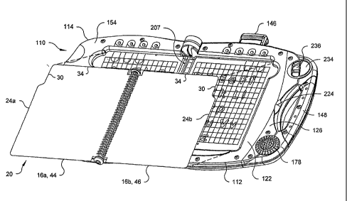
[0012] Fig. I is a top perspective view of a preferred embodiment of present
invention
showing an electronic teaching/learning device in the closed position;
3a
CA 02484362 2011-09-16
[0013] Fig. 2 is a top perspective view of the device in Fig. 1 partially
overlaid with a book
open to a two-page spread;
[0014] Fig. 3 is a top plan view of the device of Figs. 1-2 in the open
position without a
book;
[00151 Fig. 4 is a schematic of the position sensor electronics of the device
in Figs. 1-3;
[0016] Fig. 5 is a schematic of the electronics for the device of Figs. 1-3;
[0017] Fig. 6 is a fragmentary view of part of a corner of the device. of
Figs. 1-3 depicting
the construction of one of the cross-point sensor arrays;
[0018] Fig. 7 is a top plan view of a schematic of the cross-point array (or
grid) for the
position sensor of the device in Figs. 1-3;
3b
CA 02484362 2004-10-29
WO 03/102895 PCT/US03/17013
[0019] Fig. 8 is a schematic view of part of a book overlying part of a
position sensor in the
device of Figs. 1-3;
[0020] Figs. 9-11 are diagrammatic sectional views of one sensor and the
signals outputted
from the sensor for no human contact, nominally maximum human contact, and
nominally
minimum human contact, respectively.
[0021] Figs. 12 is flow diagram of the touch identification process;
[0022] Fig. 13 is a detailed schematic of a currently preferred oscillator;
[0023] Fig. 14 is detailed schematic of a currently preferred column selector
circuit;
[0024] Fig. 15 is a detailed schematic of the suggested connections of the
cross-point sensor
arrays to the other components of the sensor circuitry shown in the other
figures;
[0025] Fig. 16 is detailed schematic of a currently preferred row selector
circuit;
[0026] Fig. 17 is a detailed schematic of a currently preferred row sensor
circuit;
[0027] Fig. 18 is a detailed schematic of a currently preferred synchronous
detector,
multiplexer and filter circuit; and
[0028] Fig. 19 is detailed schematic of a currently preferred sensor
controller.
DETAILED DESCRIPTION OF THE INVENTION
[0029] An electronic teaching/learning system includes an toy, electronic,
interactive,
teaching/learning device, software and one or more books or other removable
printed planar
elements such as individual sheets, cards, stencils, etc. The software may be
stored in one or
more auxiliary processing cartridges which accompany the printed element(s),
or in a memory
within the device 100 or both. When provided together, the cartridge and
printed element are a
matched pair and are used in the device simultaneously.
[0030] Referring to Figs. 1-3, there is shown a currently preferred embodiment
of a toy
interactive, electronic teaching/learning device, generally designated 100 in
accordance with the
present invention. The electronic learning device 100 is configured for stand
alone use as well
as for receiving a book 10 or other removable printed planar element(s).
[0031] The device 100 may be configured, in particular, as an interactive book
reader that
has a sensor that can sense the location of a finger when it is placed on a
book 10 within an
active finger sensor area of the device 100. The active sensor area is
preferably matched to the
size of the book(s) or other printed sheet element(s) that might be placed on
the device 100. The
preferred sensor of the device 100 can sense the presence of a finger at a
distance of at least
about 1/4" from the planar surface of the sensor. This z (height) resolution
will allow the sensor
232085 v11 4
CA 02484362 2004-10-29
WO 03/102895 PCT/US03/17013
to detect the presence of a finger through a book that is up to at least 1/4"
thick. The sensor
preferably has an x and y resolution in planes parallel to the plane of the
sensor that is fine
enough to select every word or other graphic indicia or icon that is printed
on the book 10. The
resolution is based on the number of cross-points of the sensor, and how they
correspond
positionally to the words and graphics on the surface over the sensor or
printed on the book or
on another removable planar element such as a printed sheet or stencil that
might be used with
device 100.
[0032] The software within an auxiliary processing cartridge 146 or within the
device 100
itself contains information to produce sound effects (including music and
speech) or actions
associated with graphics and printed words within the book or other printed
removable element
or with respect to letters, words or other graphics printed on the upper
surface of the sensor.
The x and y coordinates of words or graphics and their corresponding sound
effects or actions,
are mapped into a memory located in the auxiliary processing cartridge 146 or
in the device 100
itself. Selecting any text or graphic by simply touching it will produce at
least an audio output
associated with the specifically selected text or graphic. This information
preferably is
organized in a page-by-page architecture. The user of the device 100 either
interacts with the
sensor directly using any graphics that may be printed on its surface or
places a book 10 or other
printed sheet on the sensor surface and inserts the auxiliary processing
cartridge 146 (if
required) for that book into an auxiliary slot 144 of the device 100 and
interacts through the
printed object 10 and the sensor. The device 100 can then produce an
appropriate audio output
in response to a finger touch on any word or graphic. This open architecture
allows for infinite
books and software to be used on the generic device 100.
[0033] Referring to Figs. 1-3, the device 100 has a housing assembly or simply
"housing"
110 configured in particular to receive the book 10 when the book is in the
predetermined
orientation with upper, lower, left and right sides proximal to upper, lower,
left and right sides
of the device 100. The housing 110 comprises two generally planar platforms, a
base 112 and a
cover 114 joined by hinges 180, 182, as well as a book mounting assembly 118,
latch 220 and a
hand grip 148. The first platform, the base 112, has a first base recess 128
with a first, planar
recessed surface 130. The base recess 128 is bounded by a recessed edge 132
and first, second
and third recess border sidewalls 134, 136, 138. Below surface 130 is user-
responsive position
sensor in the form of a matrix of separate but crossing conductive lines
constituting a first cross
point sensor array 142 discussed below. A cartridge slot 144 may be provided
at the top of the
base 112 for receiving a removable ROM cartridge 146 as will be discussed for
use with book
232085 v11 5
CA 02484362 2004-10-29
WO 03/102895 PCT/US03/17013
or other removable printed planar element (e.g. sheet or card or template)
used with the
device. The second platform, the cover 114, has a second, cover recess 156
with a second,
planar recessed surface 158. The cover recess 156 is bounded by a recessed
edge 160 and first,
second and third border recess sidewalls 162, 164, 166. Beneath the second
cover contact
surface 158 is a second sensor in the form of a matrix of separate but
crossing conductive lines
constituting a second cross point sensor array 170 discussed below. A speaker
retainer 176
supports a speaker 178. Hinges 180 and 182 are hollow and configured to
provide a
passageway (not depicted) through each hinge for electrical conductors (not
shown) connecting
electronics in the base 112 to electronics in the cover 114.
[00341 Referring to Fig. 2, a preferred book 10 has a plurality of pages 16
connected by a
binding 17. Any adjoining pair of the plurality of pages, like first and
second pages 16a, 16b,
can be opened into a two-page spread 20. The two-page spread 20 has opposed
side edges 24a,
24b distal to the binding 17. Book 10 is designed to closely fit in the device
100 with minimal
movement. In particular, housing 110 has a book well 208 formed by combination
of the base
recess 128 and the cover recess 156. Well 208 is configured to closely receive
the book 10
when the book 10 is in the upright, predetermined orientation, top, bottom,
left and right sides of
the book 10 proximal to top, bottom, left and right sides respectively of the
well 208 and in
particular, to have a clearance fit between the well and the book 10 or the
two-page spread 20.
[00351 Referring to Fig. 4 there is shown in broad terms, the components of
the electronics
240 of the device 100. The electronics 240 include a user interface 230 that
comprises in
addition to the position sensor 232 and the speaker 178, a visible signal
generator assembly 238,
controlling, for example LED's 150. Other user interfaces may be provided.
Other depicted
electronic components and circuits of the device 100 are the main controller
or microcontroller
288, coupled with each of the components of the interface 230 as well as with
a memory 290
and a speech synthesizer 292. The memory 290 may contain a non-volatile set of
instructions
290a as well as a non-volatile set of data 290b, including, for example, a map
of the book well
208 to identify the touch sensor locations of various icons like letters 274,
276 that may be
provided on the recess surfaces 130, 158 covering the sensor elements. An
external electrical
connector 144 is provided for use with an appropriate constructed cartridge
146. Such cartridge
would contain at least an accessible memory 296. Preferably, for the described
system 100, the
indicated cartridge 146 includes its own cartridge controller 294 and the
cartridge memory 296
includes both firmware instructions 296a for running the microcontroller 294
and slaving the
device controller 288 to the cartridge controller 294 as well as data 296b
that relates specifically
232085 v]] 6
CA 02484362 2004-10-29
WO 03/102895 PCT/US03/17013
to a book or other printed element which is used with the cartridge 146 and
the device 100.
Also part of the electronics but not depicted in Fig. 5 are the power supply
(battery and/or AC
converter), the on/off switch 234 and the volume control switch 236.
[0036] Fig. 5 depicts in block diagram form the positional sensor electronics
250 of Fig. 4.
The sensor electronics 250 preferably are controlled by a dedicated sensor
controller 264, for
example a Sunplus SPL13OA microprocessor, which is connected with and controls
a column
driver circuit 254, a pair of sensor circuits 256a, 256b through a row select
circuit 258, a
synchronous detector, multiplexer and filter circuit 260, which processes the
raw sensor signals
and passes processed signals to an analog to digital converter 262 for
digitization.
Alternatively, the functions of sensor microcontroller 264 might be performed
by the device
microcontroller 288. The position sensor 232 in device 100 further comprises
the cross-point
matrices or sensor arrays 142, 170 and a signal oscillator 252, which powers
the arrays 142, 170
and controls the detector 260.
[0037] Construction of the sensors 142, 170 in each housing element 112, 114
is indicated
diagrammatically in Fig. 6, which depicts the position sensor components in
the base 112.
Sensor array 142 is located directly beneath a plastic spacer 515 forming
recess surface 130.
Spaced beneath sensor array or matrix 142 is an electrically conductive metal
plate 510.
[0038] Referring to Fig. 7, each of the matrices 142, 170 have two sets of
general parallel,
individual separate and separated conductive lines arranged as a plurality of
spaced apart,
column or vertical conductive lines (also referred to as vertical grid lines)
248 and a plurality of
spaced apart, row or horizontal conductive lines or traces (also referred to
as horizontal grid
lines) 246 transverse and preferably perpendicular to the plurality of column
conductive lines
248. Referring to the sets of lines 246, 248 as "rows" or "columns" for
convenience, "rows" run
east-west/left-right while "columns" are perpendicular (or otherwise
transverse) to such "rows"
running north-south/up-down, but the nomenclature could be reversed. The set
of column
conductive lines 248 and the set of row conductive lines 246 are separated by
an electrically
insulative spacer, for example a Mylar plastic sheet. The row and column
conductive lines 246,
248 are suggestedly printed in conductive inks on opposite sides of the Mylar
sheet to provide
electrical isolation between the sets and form the matrix 170. Fig. 7 shows
matrix 142 in
accordance with an exemplary embodiment of the present invention. Matrix 170
is suggestedly
a mirror image but could be of a different configuration and construction.
Each matrix 142, 170
suggestedly includes sixteen rows 246 and sixteen columns 248 of the
conductive lines or traces
however different numbers of either or both can be used. Each point where a
row 246 and
232085 v]] 7
CA 02484362 2004-10-29
WO 03/102895 PCT/US03/17013
column 248 line cross creates a single individual "cross-point" sensor. The
sixteen by sixteen
line arrays therefore create two hundred and fifty-six individual cross-point
sensors arranged in
a rectangular array in the recess 128, 156 of each housing half 112, 114.
[00391 Fig. 8 depicts schematically part of a book 10 placed on part of a
sensor array 142 of
the device 100 and, in phantom, the hand of a user selecting the word "BALL"
with an extended
pointing finger. The operation of the interactive book-reading device 100
allows a user to select
any active area on the page of the book 10 by touching or simply pointing
sufficiently closely to
the selected area of the page with a finger. Upon selection of this active
area, speaker 178 of the
interactive book-reading device 100 outputs an audible message responsive to
this selection. By
way of example, when the finger touches the word "BALL", the interactive book-
reading device
100 may produce a spoken audio output "BALL" from the speaker 178. The audible
message is
generated in direct response to the user touching the word "BALL". Different
audible messages
would be generated if the user touched other areas of the page, for example
touching the word
"blue" would generate an audible message "blue". Touching the ball graphic on
the page could
produce a sound of a bouncing ball. Touching any areas of the book page that
do not have text
or graphics could either generate a generic sound of a single bell ring to
signify that there is no
audio associated with this area, a generic spoken audio output such as "try
again" or the input
selection could simply be ignored. The interactive book-reading device 100 can
therefore be
used to read the book, create sound effects associated with graphics on the
book or any other
activity programmed to be responsive to a finger touch. It can readily be seen
from Fig. 8 that
each word and image can be mapped to one or more x and y coordinate pairs of
either array 142,
170. For instance, the word "BALL" is located at R5, C4 and R5, C5 of the
arrays. This
location map is stored in memory along with the associated audible message
that is played when
either cross-point sensor location is selected.
[0040) Fig. 9-11 show examples of three cross-sections of the device 100
without and with
book 10. The cross-section drawings show from Figs. 9-11, the device 100
without book or
removable printed element or user presence, and a finger 505 with pages 16 of
a book 10 (at
various thicknesses). Each Fig. 9-11 further depicts a plastic spacer 515, a
plurality of the
spaced apart column (vertical) traces 248, the non-conductive (e.g. Mylar)
sheet 525 and one of
the spaced apart row (horizontal) traces 246 transverse to the plurality of
column traces 248.
The non-conductive sheet 525 supports and separates the column traces 248 from
the row traces
246 and forms with those traces arrays 142, 170. The sensor preferably
includes a conductive
232085 v11 8
CA 02484362 2004-10-29
WO 03/102895 PCT/US03/17013
plane 510 in the form of a metal plate, connected to system ground and
parallel to and spaced
away from the arrays 142, 170.
[0041] The plastic spacer 515 which forms the upper surface 130, 158 of either
recess 128,
156, is approximately 0.080" thick and is placed on top of either array 142,
170 to act as an
insulator so that touch surface of the sensor is separated from the matrix
142, 170 by at least this
amount. The spacer 515 may be a styrene or ABS with a dielectric constant
between about 2
and 3 although the thickness and dielectric constant can be adjusted to
achieve the desired
sensitivity. The function of the spacer 515 is to provide a stable response
from the matrix 142,
170. Eliminating the spacer 515 would cause the cross point sensors of the
arrays to be much
D more sensitive, so highly sensitive that single pages 16 would dramatically
change the output of
the arrays 142, 170. The effect of adding pages is relatively negligible (e.g.
15-20 milliVolt)
with the spacer 515 in place but could be more than an order of magnitude
greater without the
spacer. By separating the pages 16 of the book 10 from the matrix 142, 170 by
the thickness of
the plastic spacer 515, the effect on the matrix 140, 162 is greatly reduced.
As stated
5 previously, the width and thickness of the column traces 248 (vertical
columns) and row traces
246 (horizontal rows) should be kept to a minimum at the cross-points to
reduce the capacitive
effect at each of the cross-points but are preferably increased between the
cross-points and
around the cross-points, for example, by widening the individual row and
column traces into
four pointed stars or diagonal squares or the like around and between the
cross-point locations.
D [0042] Conductive plane 510 is suggestedly spaced about one-quarter inch (5
mm) below
the matrices 142, 170. The conductive plane provides shielding for the
matrices 142, 170 and as
a result, affects the area sensed around each cross-point in the matrices 142,
170. The spacing
of the plane 510 perpendicular to the planar arrays 142, 170 can be adjusted
to adjust the size of
the sensitive or sensing (i.e. user selective) area around each cross point so
that the sensing
5 areas of adjoining cross-points do not overlap.
[0043] Referring to Fig. 7, the individual traces 246. 248 are extended to
side and bottom
edges of the sheet 525 supporting the traces. Preferably, shorter traces 530
and 535 are
extended from the side and bottom edges, respectively, of the sheet 525, one
shorter trace 530 or
535 on either side of each sensor trace 246 or 248, respectively. The shorter
traces 530 and 535
0 are all connected to system ground through or with the conductive plane 510.
The horizontal
traces 530 extend inwardly from the vertical edge to just beyond where the row
traces 246
widen out to form terminals and, with a uniform length, provide some impedance
control.. The
vertical traces 535 extend from the bottom edge up to a point where the
vertical traces 248 begin
232085 v11 9
CA 02484362 2004-10-29
WO 03/102895 PCT/US03/17013
to run parallel, just below where those traces are flared and to within about
one-half inch
(12 mm) of the lowest cross-points. Traces 535 prevent cross coupling between
the column
traces 248 when the columns are being driven by oscillator 252.
[0044] Generally speaking, the values of signals generated by matrices 142,
170 are read
i and stored without human interaction with the arrays to obtain a reference
value for each cross-
point. The reference value of each cross-point sensor is individually
determined and updated.
Preferably, each is a running "average" of successive scan values (e.g. about
sixteen) for the
cross-point. Successive scans are compared to the reference values to
determine the proximity
of a human finger or other extremity. In accordance with a preferred
embodiment of the present
invention, data is accumulated starting at zero when the device 100 is powered
on. A side effect
of this is if the user has his or her finger on the matrices 142, 170 when
this process takes place,
the reference values for the touched points are lowe"r than they would be
without the touch.
[0045] Operation of the sensor 232 is as follows. Although not required, the
sensor 232
preferably is read by reading the individual touch point sensors one row at a
time alternating
arrays 142, 170 for each row 256. Firmware associated with microcontroller 264
directs the
column driver circuit 254 to pass the RF excitation signal, for example, a 250
kHz, 3300
milliVolt square wave signal, from oscillator 252 to column traces 248 of the
two arrays 142,
170, preferably in sequence, driving the same positioned column in each array
142, 170
together. The firmware also directs the row select circuit 258 to generate
appropriate control
signals sent to the (row) sensor circuits 256a, 256b to alternately connect
the same positioned
row trace 246 in each array 142, 170 to the synchronous detector, multiplexer
and filter circuit
260 as the column traces 248 are sequentially driven across each array 142,
170. The controller
264 further controls the transfer of data from circuit 260, which generates a
dc level analog
voltage signal, through A/D converter 262. Corresponding rows 246 are sampled
on each array
142, 170 before the next successive row is sampled, all with the same driven
column in each
array. Thus, the firmware cycles the arrays 142, 170 fastest, the rows 246
second fastest and the
columns 248 slowest. Preferably but not necessarily, the rows 246 are scanned
bottom to top
while the columns are driven innermost to outermost (right to left for 170,
left to right for 142).
[0046] After the initial values from arrays 142, 170 are stored, the arrays
142, 170 are
cyclically and continually scanned, and the results for each cross-point
sensor are compared
with the stored reference values, which are themselves cyclically and
continuously updated. If
any individual cross-point sensor value has a differential from its reference
value that is greater
than a predetermined or threshold amount ("Threshold"), the controller 264
will mark the point
232085 v11 10
CA 02484362 2004-10-29
WO 03/102895 PCT/US03/17013
as "touched" or "selected". A fixed threshold is established for the device
100 by characterizing
the device 100 during manufacture. For the circuitry, materials and structure
described, it has
been found that with an applied 3300 milliVolts, 250 kHz square wave signal,
individual cross-
point sensors of the arrays 142, 170 output signals of about 2200 milliVolts +
400 milliVolts
without user interaction. Deflection of the signal (i.e. a drop in detected
signal strength) at each
cross-point sensor location for user contacts ranging between that of a large
adult directly
touching the recess cover surface to a small child touching the top of a
closed book 10 on the
top of such surface range from about 1600 milliVolts in the first case to only
about 200-300
milliVolts in the second case. The threshold should be set as close as
possible to the smallest
expected user generated deflection. In this device 100 being described, the
threshold is
suggestedly set for less than 200 milliVolts, preferably between about 190 and
200 milliVolts,
for each cross-point sensor. If the measured voltage value for the cross-point
being sensed is
less than the reference value in memory by an amount equal to or greater than
the threshold
amount, the point is considered touched and is "marked" as such by the sensor
controller 264. If
the difference is less than the threshold, the reference value is updated each
64 milliseconds
period (full scan time), resulting in a settling of the reference values after
about one second.
After the matrices 142, 170 are scanned, cross-points that have been "marked"
as a touched for
two scan cycles are considered valid and selected for further processing by a
"best candidate"
algorithm as will be described.
[00471 For the described device 100, every 250 microseconds, two (2) cross-
points
(identically-positioned cross-points associated with each array 140,172) are
preferably scanned
and the associated data clocked into the sensor controller 264. For each
sensor scan, each cross-
point data value is preferably initially compared to a "High Limit" value. If
the data value
exceeds this High Limit value, it is ignored as a candidate for that scan and
ignored for updating
the reference value for that sensor. The purpose of the High Limit value is to
prevent
abnormally high data values from causing a cross-point sensor to appear
permanently pressed.
To understand the mechanism behind this requires an understanding of the
concepts described
below. Therefore, the function of the High Limit will be described later in
this section.
[00481 As noted above, for each array scan, each time the data value
associated with a cross-
point sensor is read, it is compared against the reference value, which may be
thought of and
herein referred to as a "Running Average" associated with that cross-point
sensor (see below). If
the data value is less than the Running Average minus the Threshold, the cross-
point sensor is
considered "touched" for that scan. The Threshold is the fixed data value
mentioned above (i.e.
232085 vt I 11
CA 02484362 2004-10-29
WO 03/102895 PCT/US03/17013
190 to 200 milliVolts), which represents the minimum deflection which is
expected to indicate
that a cross-point sensor is considered touched.
[0049] If the data value does not indicate that the cross-point sensor is
considered touched
(that is, data value < [Running Average - Threshold]), then the data value is
used to update the
Running Average. Upon power-up of the system, the Running Average for each
point is set to
zero. Each time the data value for a cross-point sensor is not greater than
the High Limit, and
not low enough to indicate that the cross-point sensor is touched, the data
value is used to
update the Running Average for that point. The formula used to compute the new
Running
Average is as follows:
[0050] New Running Average = Running Average + (data value - Running
Average)/16
Thus, the preferred "running average" is not truly an average but rather a
convergence
algorithm.
[0051] With the above knowledge, the function of the High Limit algorithm can
now be
explained. The reference value/running average algorithm can be fooled by
situations where
high levels of interference exist and the cross-point sensor readings climb
significantly.
Without the High Limit cut-off, abnormally high data values (due to a
continuous noise source)
could eventually result in an abnormally high Running Average for a given
cross-point sensor.
Then, when the scanned data values return to their nominal value range, if the
data values being
scanned are low enough such that the data values are greater than the
abnormally high Running
Average minus the Threshold, the cross-point sensor will be considered
touched. This will result
in newly scanned data values never being used in the calculation of the
Running Average and
therefore, will not allow the Running Average to be lowered to it's normal
level, causing the
cross-point sensor to appear permanently touched during the duration of use of
device 100.
Consequently, the only sensor data which is used or stored is that data which
is less than the
High Limit. For device 100 as described above, a High Limit value of 3100
milliVolts (about
fifty-percent higher than the nominal voltage) is suggested.
[0052] In the preferred embodiment, the device 100 further includes a "Fast
Recovery"
algorithm. This compares the latest reading from a cross-point to the
reference value or
Running Average. If the latest reading if higher by more than the Fast
Recovery Threshold, the
reference value will be set equal to the latest reading. This algorithm
counters a situation where
the user "hovers" a finger over a point for an extended period of time, which
artificially forces
the reference value down. A quick release and touch of the same point in this
situation may
cause the system not to respond because the differential between the reference
value and latest
232085 vl 1 12
CA 02484362 2004-10-29
WO 03/102895 PCT/US03/17013
reading is not more than the touch threshold value (Threshold). Figure 12
summarizes the steps
followed in identifying "touched" sensors and in updating the reference
values/Running
Averages.
[0053] The previous section described in detail how each of the 512 (16 X 16 X
2) cross-
point sensor arrays 142, 170 are determined to be activated (i.e. "touched" or
"selected") or not.
To scan the entire array of cross-points one time takes approximately 64
milliseconds (16 X 16
X 250 microseconds). During each scan, every cross-point sensor is considered
to be
activated/touched or not.
[0054] After each scan, the touched points are processed to identify a "best
candidate".
Generally speaking, the best candidate is the cross-point sensor selected by
the sensor
microprocessor as being the point most likely to have been selected by the
user in touching the
sensor. Generally speaking, it is the touched point which is highest (most
northern/Top) or the
highest and most left (i.e. most northwestern/Top Left) if two potential
candidates of equal
height are activated on a given sensor array 142, 170. For convenience, these
will be referred to
collectively as simply "the most northwestern" point. Also, the cross-point
sensor preferably
must be "touched" for two consecutive 64 millisecond scans to be considered as
the new most
northwestern point of the sensor. The process is also depicted in Fig. 12.
[0055] The sensor controller 264 first identifies a set of touched sensors. It
next identifies
those which have been touched for at least two consecutive 64 millisecond
cycles. These are the
new most northwestern candidate sensors. Preferably, the left hand array 140
is processed for
new most northwestern candidates before the right hand array 172 is processed
and the left hand
array given priority over the right hand array in each scan. What this means
is that if a new most
northwestern candidate point/sensor identified on the left hand array is lower
than a new, higher
most northwestern candidate point/sensor identified on the right array, the
left array candidate
will still be selected as new most northwest point/sensor for processing for
best candidate.
Once the best candidate has been chosen, its identification/location is
communicated from the
sensor controller 264 to the base unit microcontroller 288.
[0056] The priority of the left hand array over the right hand array,
described above, only
comes into effect when a cross-point sensor on each array is first touched
within a single 64
millisecond scan. However, it can extend to a two scan (128 milliseconds)
"preferential
treatment" for the left hand array if desired. Both scenarios are described in
the following
examples:
232085 vii 13
CA 02484362 2004-10-29
WO 03/102895 PCT/US03/17013
[0057] If a relatively lower cross-point sensor in the left hand array 142 and
a relatively
higher cross-point sensor in the right hand array 170 are both touched during
the same 64
millisecond scan, the cross-point sensor on the left sensor array 142 is
chosen as the potential
new most northwestern point if that same left sensor array cross-point is
still touched during the
next scan.
[0058] If a relatively higher cross-point sensor on right sensor array 170 is
touched and
chosen as the potential new most northwestern candidate during a 64
millisecond scan cycle,
and if a relatively lower cross-point sensor in left hand array 142 is touched
during the next 64'
millisecond scan cycle and is the new most northwestern point candidate of
that array, then the
new most northwestern point sensor (the lower cross-point sensor) in left hand
array 142 is
chosen as the new most northwestern point candidate, if that left array point
is still touched
during the next scan and is processed accordingly.
[0059] Once a new most northwestern point (cross-point sensor) has been
chosen,
preferably a "Southern Lockout" algorithm takes effect for that array 142 or
170. The Southern
Lockout algorithm causes any point of the same array touched in subsequent
scans below the
new most northwestern point to be ignored until the earlier of one second
expiration while the
new most northwestern point remains selected, or the new most northwestern
point is released.
After the lockout, all cross-points of the array become candidates for new
most northwestern
point. This algorithm covers the situation where the user rests the heel of
the pointing hand on
the array after forger touching the array.
[0060] The Southern Lockout, when used, preferably only takes effect for the
one array 142,
170 on which the new most northwestern point/sensor resides. That is, the
following scenario
can occur. The new most northwestern point/sensor is selected from the right
array. All other
cross-point sensors on that particular array which are south of the new most
northwestern
point/sensor are "locked out" for one second or until the new most
northwestern point/sensor is
released. During that one second period, a cross-point sensor on the left
array, which is the
most northwest sensor candidate touched on that array, can be selected as the
new most
northwestern point of the two arrays if it is touched for two consecutive
scans. This is a result
of arbitrarily giving the left sensor array 142 priority between the two
arrays 142, 170.
[0061] Preferably, a "Peak Search" algorithm is employed after a new most
northwestern
point of the sensor (two arrays 142, 170) is identified. The deflection of the
cross point sensors
immediately East (right), South (below) and Southeast (below right) of the new
most
northwestern point sensor are examined for touch and the relative deflections
of any touched
232085 v11 14
CA 02484362 2004-10-29
WO 03/102895 PCT/US03/17013
sensor of the four compared to one another. The one sensor of those up to four
sensors having
the greatest deflection (i.e. change from reference value/Running Average) is
selected as the
"Best Candidate" and its identity/location/position is passed to the main
(base unit)
microcontroller 288.
[0062] Each time a new best candidate is selected, its position is transferred
by the sensor
control circuit to the main (base unit) control circuit 288. Since it takes
only two 64 millisecond
scans to determine a best candidate and it is possible to find a potential new
best candidate on
either array consecutively, it is possible that a new best candidate could be
sent to the main
controller 288 on consecutive scans. The main controller 288 would then decide
how to use this
information (interrupt current activity or not, use a neighbor cross-point
sensor instead of the
best candidate, etc.).
[0063] The device 100 will also look to see if there are multiple hands placed
on the book
due to the user inadvertently placing more than one hand on the book. In the
event that the
book reader sensor sees two hands placed on the sensor, it will look to see if
either input is a
clearly defined most northern point. If so, it will select this input as best
candidate. Instead of
having to generate an audio output to direct the user to use "one finger at a
time" or any other
appropriate statement when the device 10 cannot determine with reasonable
accuracy the likely
input, the present invention can select a "best candidate" based on the above-
mentioned
algorithm.
[0064] Fig. 13 is a schematic of a currently preferred signal oscillator
circuit 252. The
signal oscillator circuit 252 generates and supplies a square wave signal
having a frequency of
approximately 250 kHz at 3.3 V to column driver circuit 254. The same signal
is passed via line
253 to the synchronous detector, multiplexer and filter circuit 260 for
synchronous detection of
the array coupled oscillating signal.
[0065] Fig. 14 is a schematic of a currently preferred column driver circuit
254. Column
driver circuit 254 sequentially excites the column lines of the matrices 142,
170, one pair of
corresponding lines at a time under the control of circuit 264. Preferably
four multiplexers
254a-254d are used to drive the thirty-two column traces 248 in the two arrays
142, 170.
[0066] Fig. 15 is a schematic diagram of currently preferred connections of
the two cross-
point sensor array 142 with the column driving and row sensing circuit
elements. Array 170 is
suggestedly a mirror image.
[0067] Fig. 16 shows schematically, a currently preferred construction of the
row select
circuit 258, which is also formed primarily by four multiplexers 258a-258d.
232085 v] 1 15
CA 02484362 2004-10-29
WO 03/102895 PCT/US03/17013
[0068] Fig. 17 depicts a currently preferred construction of one of two
preferably identical
sensor circuits, sensor circuit "B" (256b of Fig. 5), which detects signals
from the row traces
246 of the right sensor array 142 shown in Fig. 15 and forwards the detected
signal output
("PANEL R") to the synchronous detector, multiplexer and filter circuit 260
under control of
the row select circuit 258. These sensor circuits 256a, 256b impose a high
impedance load on
the coupled row traces 246 through the use of individual transistor/amplifiers
Q 1- Q 16 in the
depicted circuit 256B. The outputs (SENSE -RI through SENSE-RI 6) are
maintained normally
high by the row selector circuit 258 and dropped for individual transistors Ql
- Q16 by that
circuit when a row 246 is being "sensed".
[0069] Fig. 18 is a schematic of a currently preferred construction of the
synchronous
detector, multiplexer and filter circuit 206 showing outputs of arrays 142,
170 (PANEL_L,
PANEL R), the analog output (POINT ANALOG) of circuit 260 and the timing input
(CONTROL_8) from the sensor controller 264. The circuit element "U10" is a
multiple switch
chip that couples the output of the left sensor array 140 with a synchronous
detector/differential
amplifier 260a formed by capacitors C24 and C25 and amplifiers U1 IA and U11B
with related
circuitry. The output of that detector/amplifier pair is passed to a filter
260b formed by
amplifier U 12A and related circuitry and returned to pin ZO for multiplexing
by chip U 10 to the
A/D converter 262. The parallel circuit connected to pins Y0, Yl and Zl
operates on signals
from the other array 172. The circuit 260 operates at the 250 kHz rate of the
output signal of
oscillator circuit 252 on line 253.
[0070] Fig. 19 shows a currently preferred construction of the sensor
controller or control
circuit 264. Control circuit 264 preferably includes a general-purpose
microprocessor, such as
SunplusTM Part No. SPL130A, or the like. The A/D converter might be a
MicroChip MCP 3001
external A/D converter. The power supply (not depicted) of device 100 provides
power to
sensor circuit 232.
[0071] It will be appreciated by those skilled in the art that changes could
be made to the
embodiments described above without departing from the broad inventive concept
thereof. It
should be appreciated that the present invention can be used directly, for
example, without a
book or card or sheet, but with indicia formed or printed on an upper surface
over the circuit
with software responsive to the designation of different locations on the
surface by touching or
nearly touching the location on the surface. In this way, the present
invention could be used in
place of other conventional touch screens in other book-reading devices as
well as in other
educational and entertainment device. It is understood, therefore, that this
invention is not
232085 vl 1 16
CA 02484362 2004-10-29
WO 03/102895 PCT/US03/17013
limited to the particular embodiments disclosed, but it is intended to cover
modifications within
the spirit and scope of the present invention as defined by the appended
claims.
232085 A1 17