Note: Descriptions are shown in the official language in which they were submitted.
CA 02485303 2004-11-08
WO 03/101878 PCT/AU03/00668
1
TITLE:
"A CRANE ASSEMBLY"
FIELD OF THE INVENTION
The present invention relates generally to an improved crane
assembly. The invention has particular application to a manually operated
suspended (or overhead) crane assembly, which is configured to provide
easier operation for the assembly operator. The invention will therefore be
described in this context. However, it will be appreciated that the invention
has broader application and is not limited to that particular use.
BACKGROUND OF THE INVENTION
Manually operated suspended crane assemblies such as a
gantry crane or bridge crane are used in a great variety of industrial and
other applications for lifting and moving objects. Suspended crane
assemblies can be designed to lift and move any practical weight.
Existing suspended crane assemblies generally include a
crane, which is suspended from a trolley that is, in turn, suspended from at
least one bridge. The trolley is capable of longitudinal movement along the
at least one bridge. The at least one bridge is movably supported (generally
in a suspended manner) at either end from a pair of parallel tracks or guides.
The tracks or guides are generally mounted to a building ceiling or roof
structure. Alternatively, the tracks or guides (hereinafter referred to simply
as "guides") could be supported from a steel superstructure. This is a
particularly attractive option in situations where the building ceiling or
roof
structure concerned is not designed to bear loads.
One problem with existing assemblies occurs when an operator
attempts to initiate movement of the bridge in either direction relative to
the
guides. The effort required to initiate such movement is often considerable,
at least in part owing to the fact that movement of the other end of the
bridge
is initiated. This can cause the bridge to twist relative to the stationary
guides, and thereby jam and prevent further movement.
Another problem with existing assemblies is the fact that the
guides must be aligned parallel or very close to parallel during installation.
If
CA 02485303 2004-11-08
WO 03/101878 PCT/AU03/00668
2
not, the bridge tends to jam in the guides preventing further movement.
OBJECT OF THE INVENTION
It is an object of the invention to overcome or alleviate one
or more of the above problems of lifting assemblies or to provide the
consumer with a useful commercial choice.
SUMMARY OF THE INVENTION
According to one aspect, the present invention provides a lifting
assembly comprising:
a pair of parallel guides;
a carriage associated with each parallel guide and movable
along the length of said guide;
a connection means pivotally connecting each said carriage to
one end of a bridge; and
an attachment means associated with the bridge;
wherein said connection means includes a universal
connection to absorb rotational and lateral motions of the bridge when a
force is applied to the attachment means.
The attachment means is suitably connected to a trolley
located on the bridge and that is movable along the bridge.
The lifting device could be rigidly connected to the bridge.
However, more preferably, the lifting device is movable along the bridge on
the trolley. This desirably enables greater manoeuvrability of the lifting
device. The lifting device could be movable by any suitable means. Most
preferably, the lifting device is manually movable relative to the bridge.
However, the lifting device could instead be movable, for example,
electrically relative to the bridge.
In a preferred form, the lifting device is a crane. The crane
could be raised and lowered to lift an object by any suitable means. In
particularly envisaged forms, a manually and/or electrically operable crane
could be adopted to raise and lower an object.
It is to be appreciated that the assembly does not include the
lifting device, or part thereof. The inclusion of the lifting device in the
CA 02485303 2004-11-08
WO 03/101878 PCT/AU03/00668
3
discussion of the present invention is merely provided to define the context
of the invention.
Most preferably, each bridge is longitudinally displaceable
relative to the carriages. This further prevents the carriages from jamming
on/in the guides. In one preferred form, the longitudinal displacement is
provided by way of a displacement arm, which is pivotally connected at either
end, respectively, to the bridge and the carriages. However, longitudinal
displacement could occur via any other suitable arrangement.
The pivotal connection of the carriages to the bridge could
adopt any suitable form. The pivotal connection acts as a universal joint with
the displacement arm. The pivotal connection enables the carriages to
commence movement along one guide prior to the carriages commencing
movement along the other guide(s). This pivotal connection effectively
absorbs lateral and axial movement of the bridge and translates applied
force into longitudinal movement of the bridge along the guides. This has
been found to reduce the exertion necessary to initiate movement of the
carriages. It has also been found to reduce the incidence of the carriages
becoming jammed on/in the guides. The displacement arm is also pivotally
connected to a bridge sleeve which is rigidly fixed to the bridge.
Preferably, the bridge includes an at least one substantially
horizontally extending beam or girder. The beam or girder could be any
suitable profile, including an I-beam or a thin walled open section such as a
C-section. A single bridge could be used to support the lifting device.
However, the use of two or more bridges could also be adopted, thereby
enabling the bridges to be longer, for comparable loads, and so may be
preferred in some applications. The use of two or more bridges also enables
larger loads to be lifted, and enables a lower overall lifting device height
to be
achieved.
In one particularly preferred form, the carriages include guide
rollers, which are provided to enable longitudinal movement of the carriages
along the guide. However, it is to be appreciated that the carriage could
adopt and/or include any other suitable form.
CA 02485303 2004-11-08
WO 03/101878 PCT/AU03/00668
4
The carriages could be moved relative to the guides by any
practical means. While, it is particularly preferred that the carriages be
manually movable relative to the guides, it is to be appreciated that the
carriages could be moved relative to the guides by, for example, electrical
means.
Any practical number of guides could be incorporated into the
crane assembly. Most preferably, however, two guides are provided, with
the bridge spanning across the two guides.
The guides could adopt any suitable length and any suitable
profile or cross-section. Possible guide designs include hollow C-sections
(thin walled open channel sections) with inside-running surfaces, and I-beam
sections with outside-running surfaces.
Furthermore, the guides could be supported at any suitable
height by any suitable means. In one form, the guides could be supported
from a building roof and/or ceiling, or from a specially erected
superstructure.
It will be convenient to hereinafter describe an embodiment of
the invention in greater detail with reference to the accompanying drawings.
The particularity of these drawings in the related description is to be
understood as not superseding the generality of the preceding broad ,
description of the invention.
BRIEF DESCRIPTION OF THE DRAWINGS
Embodiments of the invention will now be described with
reference to the accompanying drawings in which:
FIG. 1 is a perspective view of an overhead lifting assembly
according to an embodiment of this invention;
FIG. 2 is a front view of a carriage illustrated in FIG 1;
FIG. 3 is a partial cross-sectional view of the carriage illustrated
in FIG 2;
FIG. 4 is perspective view of an overhead lifting assembly
according to another embodiment of this invention;
FIG. 5 is a front view of a carriage illustrated in FIG. 4; and
FIG. 6 is a partial cross-sectional view of the carriage illustrated
CA 02485303 2004-11-08
WO 03/101878 PCT/AU03/00668
in FIGS.
DETAILED DESCRIPTION OF THE PREFERRED EMBODIMENTS
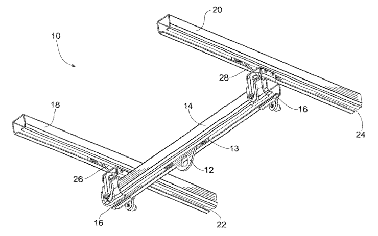
FIG. 1 illustrates a lifting assembly 10. A lifting device in the
form of a manually operated crane (not illustrated) may be suspended from
5 the lifting assembly by attachment means 12. The attachment means 12
could be a hook, chain or other suitable device. It is to be appreciated, that
the lifting device could adopt any suitable form. For example, the lifting
device could be a manually or an electrically operated crane.
The attachment means 12 is connected to a trolley 13. The
trolley 13 is movably suspended from a bridge 14. The bridge 14 could be in
the form of an open channel section, an I-beam, or any other suitable form.
The trolley 13 includes trolley rollers being wheels, ball bearings or other
suitable propulsion means. The rollers are capable of rolling longitudinally
along the bridge 14. The trolley rollers could adopt any suitable form. In
this
respect, the trolley rollers could include plastic coated rolling surfaces for
silent running. Alternatively, the rollers, including the roller surfaces,
could
be constructed from steel. Alternatively other mechanisms could be used in
place of rollers, such that the trolley 13 is movable along the length of the
bridge 14.
The attachment means 12 extends through an opening 16
provided in the underside of the bridge 14. In this way the attachment
means 12 (and crane) is movable along the length of bridge 14. Where the
bridge does not have a slot, the attachment means 12 is connected to the
trolley 13 or bridge 14.
It is to be appreciated that the attachment means 12 could be
movably connected to two or more bridges 14.
Two substantially parallel guides 18,20 are provided. The
bridge 14 is movable longitudinally relative to the parallel guides 18,20. In
the illustrated embodiment of the invention, the bridge 14 is manually
movable relative to the parallel guides 18,20. Again, however, it is to be
appreciated that the bridge 14 could be electrically movable relative to the
parallel guides 18,20
CA 02485303 2004-11-08
WO 03/101878 PCT/AU03/00668
6
The parallel guides 18,20 as shown formed from an open
channel C-section are respectively provided with openings 22,24.
In the illustrated embodiment the parallel guides 18,20 are
rigidly secured to a building ceiling, roof or separate superstructure (not
illustrated). However, it is to be appreciated that the parallel guides 18,20
could be provided with some movement relative to their mountings, if
desired.
The bridge 14 includes carriage 26,28. The carriages 26,28 are
provided for travelling along the parallel guides 18,20 respectively. The
relationship and configuration of the carriage 26 and the guide 18 is
substantially identical to that of the carriage 28 and fihe guide 20.
Therefore,
the following description, with reference to FIGS. 3 and 4, in part, refers
only
to the carriage 26 and the guide 18.
The parallel guides 18,20 are illustrated in FIG. 1 as being
open channels in profile, and therefore include an internal track system. It
is
to be appreciated, however, that the guides 18,20 could adopt other suitable
profiles, including I-beam (or external track) profiles, as shown in FIGS. 4,
5
and 6.
The carriage 26, or similar device, is movable along the parallel
guides 18,20, and includes at least one mounting plate 30. The mounting
plate 30 is configured to travel longitudinally along the parallel guide 18 by
way of rollers 32,34,36,38, which are rotatably mounted to the mounting
plate 30. The carriages 26,28 bear the weight of the bridge 14 and the crane
(not illustrated), which is, in turn, borne by the parallel guides 18,20. An
additional mounting plate 30 may be used external of the profile (I-beam).
Preferably, the rollers 32,34,36,38 include tapered surfaces
thereby enabling the rollers 32,34,36,38 to roll efficiently along the guides
18,20. The rollers 32,34,36,38 include plastic (or rubber) coated rolling
surfaces. The plastic coated rolling surfaces are provided to reduce rolling
noise of the rollers 32,34,36,38. It is to be appreciated, however, that the
rollers 32,34,36,38 need not include plastic coated rolling surfaces. The
rollers 32,34,36,38 could instead include, for example, steel rolling
surfaces.
CA 02485303 2004-11-08
WO 03/101878 PCT/AU03/00668
7
Furthermore, it is to be appreciated that the rollers 32,34,36,38
could be replaced by another suitable arrangement such as, for example, a
bearing arrangement.
Existing crane assemblies tend to jam when an operator
initiates movement of the bridge (comparable to the bridge 14) along the
assembly guides (similar to guides 18,20). This is, in part, a result ofthe
rigid
connection in existing crane assemblies of the bridge to the carriage.
To address this problem, the present invention includes a
displacement arm 40. The displacement arm 40 is constructed from mild
steel, or higher-grade steel, generally from steel plate or steel strip.
Alternatively, the displacement arm 40 could be constructed from any other
suitable material. The displacement arm 40 is pivotally connected to a
sleeve 42. The sleeve 42 is rigidly fastened (by any suitable means) to the
mounting plate 30. The figures show the mounting plate 30 welded to the
sleeve 42, but other means of rigid attachment such as bolting could be
used. The pivotal connection between the displacement arm 40 and the
sleeve 42 is by way of a ball bearing 44. The ball bearing 44 is retained in
place by a ball bearing seat 46 provided in the displacement arm 40 and the
sleeve 42, respectively. The ball bearing 44 could be manufactured from any
suitable grade of steel, or any other suitable material. The bearing seat is
formed from a plastic, such as nylon, to minimise friction, but could be
formed from other suitable materials.
The displacement arm 40 is pivotally connected to a bridge
sleeve 50 (see FIGS. 2 and 3) which, in turn, is securely connected to one
end of the bridge 14. The bridge sleeve 50 is constructed from steel. Any
suitable grade steel (or any other material) could be used in the construction
of the bridge sleeve 50. The displacement arm 40 is pivotally connected to
the bridge sleeve 50 by two fasteners 52,54 via displacement arm
appendages 56,58. The fasteners 52,54 provide a pivotal connection
between the displacement arm 40 and the bridge sleeve 50.
The above arrangement forms a universal joint that provides
the necessary relative pivoting and lateral movement between the carriage
CA 02485303 2004-11-08
WO 03/101878 PCT/AU03/00668
8
26,28 and the bridge 14 to at least reduce the incidence of jamming of the
lifting assembly 10, upon initiating movement of the bridge 14 relative to the
parallel guides 18,20.
It is to be appreciated that the pivotal connection of the
carriages 26,28 to the bridge 14 could adopt a configurations) different to
that specifically described above. The pivotal connection could, instead,
include a rod end, or other pivotal/rotatable linkage arrangement.
The mounting plate 30 includes a safety mechanism in the form
of anti-derailment means 30A,30B. The anti-derailment means 30A, 30B are
ball bearings or similar, which ensure the carriages 26,28 remain engaged
with the guide 18. The anti-derailment means 30A,30B are provided to
prevent the bridge 14 and crane crashing to the ground in the event of failure
of the rollers 32,34,36,38 or other parts of the carriage 26,28.
The bridge 14 and the parallel guides 18,20 are formed from
cold-rolled steel in tube or bar.
It is to be appreciated that parts) of the above-described
arrangement could be incorporated into existing assemblies. In this respect,
Applicant envisages that the arrangements illustrated in FIGS. 2, 3, 5 and 6
in their entirety or in part, could be incorporated into existing assemblies.
In FIG. 4, the lifting assembly 10 is shown for parallel guides
18,20 in the form of an I-beam rather than an open channel C-section. In
this form the carriages 26,28 capture the beam flanges between the wheels
32,34,36 and 38, as illustrated.
FIGS. 5 and 6 show the carriages 26 adapted to fit an I-beam
parallel guide 16. Similarly, the trolley 13 can be fitted to an I-beam bridge
(not shown).
The illustrated lifting assembly 10 has been designed to lift
objects of up to half a tonne in weight. However, the reader is to appreciate
that the lifting assembly 10 of the present invention could be designed to
lift
any practical weight, including weights well in excess of half a tonne.
The present invention has been found to at least reduce the
incidence of jamming experienced by existing assemblies.
CA 02485303 2004-11-08
WO 03/101878 PCT/AU03/00668
9
The present invention has been found to at least accommodate
situations in which the parallel guides 18,20 are not mounted exactly parallel
to one another.
The present invention has also been found to require less
operator efFort to initiate movement of the bridge 14 along the parallel
guides
18,20 when compared to existing assemblies.
Moreover, the present invention is particularly useful, because
it can be relatively easily incorporated into existing assemblies.
Finally, it is to be understood that various alterations,
modifications andlor additions may be introduced into the construction and
arrangement of the parts previously described without departing from the
spirit or ambit of the invention. For instance, the lifting assembly could
incorporate multiple parallel guides and multiple bridges.