Note: Descriptions are shown in the official language in which they were submitted.
CA 02485894 2011-02-14
WO 03/102517 PCT'/CA03/00803
METHODS AND APPARATUS FOR REDUCING ARTIFACTS IN
MASS SPECTROMETERS
Field of Invention
The invention relates generally to the field of mass spectrometers, and more
particularly to the art of reducing or eliminating artifacts such as "ghost
peaks" from mass
scans obtained by mass analyzing ions contained in ion traps.
Background of Invention
Quadrupole mass analyzers have conventionally been used as flow-through
devices, i.e., a continuous stream of ions enter and then exit the
quadrupoles. More
recently, however, the same quadrupole mass analyzer has been used as a
combined linear
ion trap and mass analyzer. That is, the linear ion trap accumulates and
constrains ions
within the quadrupole volume. The linear ion trap is characterized by an
elongate multi-
pole rod set in which a two dimensional RF field is used to constrain ions
radially and DC
barrier or trapping fields are used to constrain the ions axially, After a
suitable fill time,
the trapped ions are then scanned out mass dependently, for example, using a
radial or
axial ejection technique. Examples of quadrupole mass analyzers which combine
ion
trapping and mass analysis functions are described, inter alia, in U.S. Patent
No. 5,420,425
to Bier at al.; U.S. Pat. No. 6,177,668 to Hager; or in co-pending Canadian
Patent
Application No. 2,481,299 and assigned to the assignee of the instant
application.
In such quadrupole mass analyzers, the mass scan sometimes reveals ghost
peaks,
i.e., satellite peaks that appear adjacent to the main peak, making the mass
scan
questionable. An example of this is shown in Fig IA, where a mass scan 78
features a
main mass peak 82. The satellite peak 80, on the low side of the main peak 82,
is a ghost
peak or artifact. The small peak 84, on the high side of mass peak 82, is a
legitimate
isotope peak. These spectrograms were taken using a commercially available
standard
solution manufactured by AgilentTM, product no. ES Mix 02421 A, diluted in
acetonitrile
and water. Artifacts of these types have been observed on a number of mass
spectrometers
when a quadrupole rod set has been operated as a combined ion trap and mass
analyzer.
As mass increased, the severity of the artifact peaks increased in that the
mass separation
increased with mass, i.e., the problem was worst at high mass. The problem was
also
CA 02485894 2004-11-12
WO 03/102517 PCT/CA03/00803
-2-
much more evident at slow scan speeds (e.g., 250 Da/s) when the resolution is
the best.
The age of the equipment and the length of the rods was also a factor.
Depending on the
parametric conditions, primarily the barrier potential on an end section
member such as an
exit lens used to trap ions axially, the artifact peaks could be minimized but
at the expense
of the main peak intensities. Again depending on the instrument and how it is
set up the
artifact peak can be either on the high or low mass side of the main peak.
Summary of Invention
The invention reduces and in certain cases can eliminate this undesirable
phenomenon.
It is postulated that artifacts arise as a result of randomly distributed
voltage
gradients distributed along the length of the trapping quadrupole rod set.
This causes
spatially distributed and isolated ion populations of differing kinetic
energies to exist in
the ion trap. As the ions exit the trap, the isolated ion populations with the
same m/z
values will appear at the exit end at different times. Since ions exiting the
trap can
originate from anywhere along the entire length of the trap, ions of the same
m/z values
may not behave identically, causing the ghost peaks.
The invention provides three potential solutions to the artifact problem. The
first
approach involves improving the metallurgical properties of the rod sets,
especially the
conduction characteristics. The second approach involves the application of at
least one
continuous axial DC field to the trapping quadrupole rod set in order to urge
ions towards
a pre-determined region of the trap from which ions are eventually ejected,
thus
eliminating isolated ion populations. The third approach compartmentalizes the
ion trap
by applying at least one discrete axial fields to create a potential barriers
along the axial
dimension of the trap (in addition to the barriers used to initially trap the
ions). These
barriers prevent the isolated ion populations along the trap from
equilibrating with one
another.
According to one aspect of the invention, there is provided a method of
operating a
mass spectrometer having an elongate rod set which has an entrance end, a
longitudinal
axis, and a distal end. The method includes: (a) admitting ions into said rod
set via the
entrance end; (b) trapping at least some of the ions introduced into the rod
set by
producing an RF field between the rods and a barrier field adjacent to the
distal end; (c)
after trapping ions, establishing at least one additional barrier field in the
interior of the
CA 02485894 2004-11-12
WO 03/102517 PCT/CA03/00803
rod set to define at least two compartments of trapped ions; (d) ejecting at
least some ions
of a selected mass-to-charge ratio from selected, but not all, of the
compartments; and (e)
detecting at least some of the ejected ions.
In preferred embodiments, ions are detected from only one of the compartments.
This method can be implemented on mass spectrometers where ions are ejected
axially, i.e., along the longitudinal axis, or radially, i.e., transverse to
the longitudinal axis.
In the case of an axially ejecting spectrometer, the distal end functions as
an exit end for
the trapped ions and one additional barrier field is preferably produced such
that the
selected compartment is defined between the additional barrier field and the
barrier field
adjacent the distal/exit end. In the case of a radially ejecting mass
spectrometer, the
selected compartment can be defined anywhere along the rod set, preferably
provided a
detector is configured to detect ions ejecting substantially only from the
selected
compartment.
According to another aspect of the invention, a mass spectrometer is provided
comprising: a multipole rod set, which defines a volume; power supply means
connected
to the rod set for generating an RF field in the volume in order to constrain
ions of a
selected range of mass-to-charge ratios along first and second orthogonal
dimensions;
means for introducing and trapping ions in the volume along a third dimension
substantially orthogonal to the first and second dimensions; means for
defining at least two
compartments of trapped ions; and means for detecting ions from selected, but
not all, of
the compartments.
According to another aspect of the invention, an improvement is provided for
an
ion trap which employs a two-dimensional RF field to constrain ions in two
dimensions
and at least one barrier potential to constrain ions in a direction
substantially normal to
these two dimensions. The improvement includes: means for defining at least
two
compartments of trapped ions; and means for ejecting and detecting ions from
at least one,
but not all, of the compartments.
According to another aspect of the invention, there is provided another method
of
operating a mass spectrometer having an elongate rod set which has an entrance
end, a
longitudinal axis, and a distal end. The method includes: (a) admitting ions
into the rod
set via the entrance end; (b) trapping at least some of the ions introduced
into the rod set
by producing an RF field between the rods and by producing a barrier field
adjacent the
distal end; (c) establishing at least one DC field along the longitudinal axis
in order to urge
CA 02485894 2004-11-12
WO 03/102517 PCT/CA03/00803
-4-
said trapped ions towards a pre-detennined region of the volume defined by the
rod set;
(d) ejecting at least some ions of a selected mass-to-charge ratio from the
pre-determined
region; and (e) detecting at least some of the ejected ions.
This method can be implemented on mass spectrometers where ions are ejected
axially or radially. In the case of an axially ejecting spectrometer, the
distal end functions
as an exit end for the trapped ions the ions are urged towards the distal end
of the rod set.
In the case of a radially ejecting mass spectrometer, the predetermined region
can be
situated anywhere along the rod set, preferably provided a detector is
configured to detect
ions ejecting substantially only from that region.
In preferred embodiments, the DC field(s) is established by a biased set of
electrodes disposed adjacent to the rod set. Each of these electrodes has a T-
shaped cross
section including a stem, the depth of which varies over the length of the rod
set in order
to provide a substantially uniform electric field along the longitudinal axis.
Brief Description of Drawings
The foregoing and other aspects of the invention will become more apparent
from
the following description of specific embodiments thereof and the accompanying
drawings
which illustrate, by way of example only, the principles of the invention. In
the drawings:
Fig. 1A is a mass spectrogram showing the existence of artifact ghost peaks.
Fig. 113 is a mass spectrogram, obtained under conditions similar to Fig. IA,
without the artifact ghost peaks. This spectrogram was produced by employing
the
artifact-eliminating apparatus shown in Fig. 5.
Fig. 2 is a schematic diagram of a triple-quadrupole mass spectrometer having
a
linear ion trap (Q3) with which the invention may be used.
Fig. 3 is a timing diagram showing a variety of waveforms used to control the
linear ion trap (Q3) shown in Fig. 2.
Figs. 4A and 4B respectively show radial and axial cross-sectional views of a
modified quadrupole rod set/linear ion trap fitted with linacs (extra
electrodes) for
producing an axial DC field.
Fig. 5 is a perspective view of a modified quadrupole rod set/linear ion trap
fitted
with biased metalized rings for generating potential barriers along the axial
dimension of
the rod set.
CA 02485894 2004-11-12
WO 03/102517 PCT/CA03/00803
-5-
Fig. 6 is a timing diagram showing a variety of waveforms used to control the
modified linear ion trap illustrated in Fig. 5.
Fig. 7A is a schematic diagram of a modified quadrupole rod set/linear ion
trap
configured to detect ions ejected radially from the trap. The trap includes
means for
producing axial fields.
Fig. 7B is a schematic diagram of a modified quadrupole rod set/linear ion
trap
configured to detect ions ejected radially from the trap. The trap is fitted
with biased
metalized rings for generating potential barriers along the axial dimension of
the rod set.
FIG. 8 is a side view of two rods of a tapered rod set enabling the generation
of an
axial field for use in place of or in addition to one of the quadrupole rod
sets of a linear ion
trap.
FIG. 9 is an end view of the entrance end of the FIG 8 rod set.
FIG 10 is a cross-sectional view at the center of the rod set of FIG. 8.
FIG 11 is an end view of the exit end of the FIG. 8 rod set.
FIG 12 is a side view of two rods of a modified rod set enabling the
generation of
an axial field for use in place of or in addition to one of the quadrupole rod
sets of a linear
ion trap.
FIG 13 is an end view of the entrance end of the FIG. 12 rod set.
FIG 14 is a cross-sectional view at the center of the FIG. 12 rod set.
FIG 15 is an end view of the exit end of the F[G. 12 rod set.
FIG 16 is a side view of two rods of a modified rod set enabling the
generation of
an axial field for use in place of or in addition to one of the quadrupole rod
sets of a linear
ion trap.
FIG 17 is an end view of the rod set of FIG 16 and showing electrical
connections
thereto.
FIG 18 is a side view of two rods of another modified rod set enabling the
generation of an axial field for use in place of or in addition to one of the
quadrupole rod
sets of a linear ion trap.
FIG 19 is an end view of the rod set of FIG. 18 and showing electrical
connections
thereto.
FIG 20 is a side view of another modified rod set enabling the generation of
an
axial field for use in place of or in addition to on of the quadrupole rod
sets of a linear ion
trap.
CA 02485894 2011-02-14
WO 03/102517 PCT/CA03/00803
-6-
FIG 21 is a side view of another modified rod set enabling the generation of
an
axial field for use in place of or in addition to one of the quadrupole rod
sets of a linear ion
trap.
FIG 22 is a cross-sectional view at the center of the rod of FIG 21.
FIG 23 is a diagrammatic view of yet another modified rod set.
FIG 24 is an end view of the rod set of FIG 23.
Detailed Description of Illustrative EEnmbodiments
The inventors have theorized dial the artifact problem may be attributed to
metallurgical properties of the rods employed in linear ion traps ("LIT"), in
conjunction
with the geometry thereof. It was observed initially that swapping in a new
set of rods,
which are typically constructed from stainless steel, could solve this
problem. It was also
observed that in many cases when new rod sets were installed that no artifact
peaks existed
but after a period of many hours or even days the arti facts could re-appear.
Fig. 2 illustrates a triple-quadrupole mass spectrometer apparatus 10 in which
one
of the quadrupole rod sets, Q3, is operated as a combined linear ion trap and
mass
analyzer. Experiments were conducted on such an apparatus, and the invention
may be
used with spectrometers such as, but not limited to, this type.
More particularly, the apparatus 10 includes an ion source 12, which may be an
electrospray, an ion spray, a corona discharge device or any other known ion
source. Ions
from the ion source 12 are directed through an aperture 14 in an aperture
plate 16. On the
other side of the plate 16, there is a curtain gas chamber 18, which is
supplied with curtain
gas from a source (not shown). The curtain gas can be argon, nitrogen or other
inert gas,
such as described in U.S. Patent No. 4,861 988, to Cornell Research Foundation
Inc.,
which also discloses a suitable ion spray device.
The ions then pass through an orifice 19 in an orifice plate 20 into a
differentially
pumped vacuum chamber 21. The ions then pass through aperture 22 in a skimmer
plate
24 into a second differentially pumped chamber 26. Typically, the pressure in
the
differentially pumped chamber 21 is of the order of 1 or 2 TOIT and the second
differentially pumped chamber 26, often considered to be the first chamber of
the mass
spectrometer, is evacuated to a pressure of about 7 or 8 mTorr.
CA 02485894 2011-02-14
WO 03/102517 PCT/CA03/00803
-7-
In the chamber 26, there is a conventional RF-only multipole ion guide QO. Its
function is to cool and focus the ions, and it is assisted by the relatively
high gas pressure
present in chamber 26. This chamber 26 also serves to provide an interface
between the
atmospheric pressure ion source 12 and the lower pressure vacuum chambers,
thereby
serving to remove more of (lie gas from the ion stream, before further
processing.
An interquad aperture IQI separates the chamber 26 from a second main vacuum
chamber 30. In the second chamber 30, there are RF-only rods labeled ST (short
for
.1 stubbies", to indicate rods of short axial extent), which serve as a
Brubaker lens, A
quadrupole rod set Q1 is located in the vacuum chamber 30, which is evacuated
to
approximately 1 to 3 x 10⁻⁵ Torr. A second quadrupole rod set Q2 is located in
a collision
cell 32, supplied with collision gas at 34. The collision cell 32 is designed
to provide an
axial field toward the exit end as taught by Thomson and Jolliffe in U.S.
Patent No.
6,111,250, the entire contents of which are incorporated herein by reference.
The cell 32,
which is typically maintained at a pressure in the range 5 x 10'4 to l0.2
Torr, is within the
chamber 30 and includes interquad apertures IQ2, IQ3 at either end. Following
Q2 is
located a third quadrupole rod set Q3, indicated at 35, and an exit lens 40.
Each rod in Q3 has a radius of about 10 tnm and a length of about 120 mm,
although other sizes are contemplated and may be used in practice. It is
desirable for the
rods to be as close to ideal configuration as possible, e.g., perfectly
circular or having
perfect hyperbolic faces, in order to achieve the substantial quadrupole field
required for
mass analysis. Opposing rods in Q3 are preferably spaced apart approximately
20 mm,
although other spacings are contemplated and used in practice. The pressure in
the Q3
region is nominally the same as that for Q 1, namely I to 3 x 10⁻⁵ Torr. A
detector 76 is
provided for detecting ions exiting axially through the exit lens 40.
Power supplies 37, for RF, 36, 1'or RF/DC, and 38, for RP/DC and auxiliary AC
are
provided, connected to the quadrupoles QO, Q1, Q2, and Q3. QO is operated as
an RF-
only multipole ion guide whose function is to cool and focus the ions as
taught in US
Patent No. 4,963,736. Q1 is a standard resolving RF/DC quadrupole. The RF and
DC voltages are
chosen to transmit only precursor ions of interest or a range of ions into Q2.
Q2 is supplied with
collision gas from source 34 to dissociate precursor ions to produce a
fragment ions. Q3 was
operated as a linear ion trap, and used to trap the fragment ions as well as
any un-dissociated
CA 02485894 2011-02-14
WO 03/102517 PCT/CA03/00803
-8-
precursor ions. Ions are then scanned our of Q3 in a mass dependent manner
using an
axial ejection technique. Q3 can also function as a standard resolving RF/DC
quadrupole.
In the illustrated embodiment, ions from ion source 12 are directed into the
vacuum chamber 30 where, if desired, a precursor ion of a selected m/z value
(or range of
mass-to-charge ratios) may be selected by Q1 through manipulation of the RF+DC
voltages applied to the quadrupole rod set as well known in the art. Following
precursor
ion selection, the ions are accelerated into Q2 by a suitable voltage drop
between Qi and
Q2, thereby inducing fragmentation as taught by U.S. Patent Nos. 5,248,875.
The degree of fragmentation can be controlled in part by the pressure in the
collision cell.
Q2, and the potential difference between Q1 and Q2. In the illustrated
embodiment, a
DC voltage drop of approximately 40 - 80 volts is present between Q I Q2.
The fragment ions along with non-dissociated precursor ions are carried into
Q3 as
a result of their momentum and the ambient pressure gradient between Q2 and
Q3. After a
suitable fill time a blocking potential can be applied to IQ3 in order to trap
the precursor
ions and its fragments in Q3. Once trapped in Q3, the precursor ions and its
fragments can
be mass selectively scanned out of the linear ion trap, thereby yielding an
MS/MS or MS2
spectrum.
Fig. 3 shows the timing diagrams of waveforms applied to the quadrupole Q3 in
greater detail. In an initial phase 50, a DC blocking potential on IQ3 is
dropped so as to
permit the linear ion trap to fill for a time preferably in the range of
approximately 5-1000
ms, with 50 ms being preferred.
Next, a cooling phase 52 fol lows in which the ions in the trap are allowed to
cool
or thermalize for a period of approximately 10 nis in Q3. The cooling phase is
optional,
and may be omitted in practice.
A mass scan or mass analysis phase 54 follows the cooling phase, in which ions
are axially scanned out of Q3 in a mass dependent manner. In the illustrated
embodiment,
an auxiliary dipole AC voltage, superimposed over the RF voltage used to trap
ions in Q3,
is applied to one set of pole pairs, in the x or y direction (being orthogonal
to the axial
direction. The frequency of the auxiliary AC voltage, f;,,x, is preferably set
to a
predetermined frequency wj,, known to effectuate axial ejection. (Each linear
ion trap
may have a somewhat different frequency for optimal axial ejection based on
its exact
geometrical configuration.) Simultaneously, the amplitudes of the Q3 RF
voltage and the
CA 02485894 2011-02-14
WO 03/102517 PCT/CA03/00803
-9-
Q3 auxiliary AC voltage are ramped or scanned. This particular technique
enhances the
resolution of axial ejection, as taught in co-pending CA Patent Application
No.
2,481,299, assigned to the instant assignee.
After mass scanning, in a next phase 56 Q3 is emptied of all ions. In this
phase, all
of the voltages are lowered to allow the trap to empty.
In investigating the artifact phenomenon, which in the apparatus 10 arises
from
Q3, it is known that the ions which are scanned axially out of the Q3 LIT can
and do
originate from anywhere along the length of the Q3 rod set, but ions of the
same m/z value
may not necessarily exit the trap at the same time. As such, it is believed
that there are
populations of ions along the length of the Q3 rod set that are isolated from
one another by
voltage gradients, i.e., different ion populations are energized to slightly
varying voltage
potentials, and thus have slightly differing kinetic energies. Experience has
shown that
different rod sets are likely to have different isolated ion populations,
implying the
existence of randomly distributed voltage gradients on the Q3 rod sets.
As such, some ion populations in the LIT can have different kinetic energies
than
other ion populations. It is thus expected that discrete or different on
populations will
reflect off the voltage gradients or barriers including IQ3 and the exit lens
at the opposing
ends of the Q3 LIT. There may also be other mechanisms at play which result in
randomly distributed voltage gradients or barriers that manifest along the
length or axial
dimension of Q3.
The randomly distributed voltage barriers or gradients affecting the
transmission
properties are believed to arise from non-uniformities of the surface
potentials of the rods,
probably as a result of different surface compositions, either elemental or
oxides.
Oxidation likely explains why the artifact effect occurs gradually. It is
postulated that
these irregularities cause variations in the work function on the rod surface
thus varying
the effective RF voltage amplitude at different positions along the rods, See
Gerlich,
Dieter., `Inhomogeneous RF Fields: A Versatile Tool For The Study of Processes
With
Slow Ions', Advance in Chemical Physics Series, Vol. 52, pages 75-81,1992.
There are three potential solutions to the artifact problem in LITs. The first
approach involves improving the metallurgical properties of the rod sets,
especially the
conduction characteristics. The second approach involves the application of a
continuous
axial field to the LIT quadrupole rod set in order to urge ions towards the
exit end of the
CA 02485894 2004-11-12
WO 03/102517 PCT/CA03/00803
-10-
trap, thus eliminating isolated ion populations. The behavior of the LIT was
investigated
when Linacs were used for this purpose. The third approach involves the
application of
discrete axial fields to create one or more potential barriers along the axial
dimension of
the trap. These barriers prevent the isolated ion populations along the trap
from interfering
with one another. The behaviour of the LIT was investigated when potential
barriers were
created through the use of biased metallized rings surrounding the quadrupole
rod set. The
second and third approaches provide a means for precluding isolated ion
populations in
detected ions. The first approach provides a means for improving the random
potential
gradients that arise from the metallurgical properties of the rods.
1. Improved Metallurgical Properties
One approach to reducing the artifact problem is to improve the metallurgical
properties of the rod sets to have better conduction characteristics and less
of a tendency to
oxidize. The rod sets have traditionally been constructed from stainless
steel, and
manufactured using conventional machining methods. These methods are not
always
capable of meeting tight tolerance levels beyond a specific rod length (the
high tolerances
being important for achieving the substantial quadrupole field required for
mass analysis),
and so other materials and manufacturing techniques have been developed for
providing
precision-tolerance rod sets. For example, the assignee has developed
relatively long rod
sets using gold-plated ceramic rods. The following experiments were conducted
using
gold-plated ceramic rods and gold-plated stainless steel rods for the Q3 rods.
Using nine gold-coated rod sets, it was observed that 8 of 9 sets reduced
artifact
effects to acceptable levels in at least one orientation or the other
(orientation being
defined as the rods being disposed towards Q2 or alternatively towards the
detector). Only
one rod set passed in both orientations. It is postulated that the gold layer
provides an
improved uniform conductive layer therefore reducing random voltage barriers
or
gradients along the rods. However, gold-coating the rod sets only assisted in
reducing the
severity of the artifact peaks. It did not completely eliminate the
phenomenon.
Instead of gold, other metallic amorphous coatings will suffice.
II. Continuous Axial Fields
Another approach centers on creating or providing one or more axial fields in
the
Q3 LIT. One type of axial field, termed herein as a "continuous" field,
functions to push
CA 02485894 2011-02-14
WO 03/102517 PCT/CA03/1108113
-11-
or urge the ions trapped along the entire length of Q3 towards the exit end of
the rod set.
This has the effect of congregating the trapped ions and eliminating discrete
ion
populations. The axial field also ensures that substantially all ions of a
given m/z value
selected for axial ejection exit the trap at substantially the same time.
Figs. 4A and 413 respectively show radial and axial cross-sectional views of
"Manitoba"-style linacs 100, which are one example of an apparatus that can be
used to
apply a continuous axial field. The linacs include four extra electrodes 102
introduced
between the main quadrupole rods 35 of Q3. While a variety of electrode shapes
are
possible, the preferred electrodes have T-shaped cross-sections. The linac
electrodes are
held at the same DC potential 104, but the depth, d, of the stem section 106
is varied as
seen best in Fig. 4B to provide an approximately uniform electric field along
the axial
dimension of Q3. See Loboda et al., "Novel Linac II Electrode Geometry for
Creating an
Axial Field in a Multipole Ion Guide", Eur. J. Mass Spectrom., 6,531-536
(2000), for more
detailed information on this subject. The linacs 100 create a continuous DC
axial field
(symbolically represented by field lines 108) which applies a force that
pushes the ions
towards the exit end of the Q3 rod set. The artifacts phenomenon can be
substantially
eliminated using this approach.
Referring to Fig. 3, note that the axial field is preferably off during the
ion
injection phase 50, so the space charge characteristics of the trap are not
affected. (If the
axial field is on during fill time, then the fill time is reduced.) During
ejection, as the ions
exit, the space charge effects are insignificant and/o compensated for by the
axial field.
It was found that different axial gradients were required for different rod
sets to
mitigate the ghost artifact peaks. Accordingly, different rod sets may have to
be
individually tuned. Experimentally, the an LIT length of about 20 mm required
a potential
gradient of 0.05 to 0.15 volts/cm. The value call be varied with application
to compensate
for variation between instruments- Also, axial fields of different polarity
are required for
positive and negative mode ions.
In employing the linacs 100, it was noted that there was some interaction
between
the linac fields near IQ3 that affect the transmission of ions into Q3 during
the ion
injection phase 50. This could be overcome by adjusting the position of the
linacs 100
relative to the end of the rod set. More particularly, the DC field interacts
with a fringing
field created by IQ3 and the end of the Q3 rod set. This interaction has an
affect on ions
CA 02485894 2011-02-14
WO 03/102517 PCT/CA03/00803
-12-
filling the trap in that it reduces the fill amount. In order to avoid this
interaction, the end
of the linac electrode is moved away from the end of the rod set by 1 to 4 mm,
Typically,
the fringing field penetrates into the rod set by a distance equivalent to
about a'/2 rod
radius, or about 6mm in the illustrated embodiment. So, about a 4mm gap is
sufficient to
elevate this interaction. It also appears that normal RP/DC resolving mode of
operation is
not significantly affected by the presence of the linac hardware when
appropriate voltages
are applied.
A variety of other mechanisms can be used in the alternative to create a
continuous
axial field in a linear ion trap that will eliminate the artifact problem. A
number of these
are described in U.S. Patent Nos. 5,847,386 or 6,11 1.250 to Thomson and
Jollife.
Although these patents describe the creation of an auxiliary axial field in a
standard
resolving quadrupole or a collision cell where ions are not trapped,
nevertheless most
of these can be used for an ion trap.
Briefly, as described in the patents above, axial fields can be created in one
or
more rod sets by: tapering the rods (Figs, 8 to 11); arranging the rods at
angles with
respect to each other (Figs. 12 to 15); segmenting the rods (Figs. 16-17);
providing a
segmented case around the rods (Figs. 18-19): providing resistively coated or
segmented
auxiliary rods (Figs. 18-19); providing a set of conductive metal bands spaced
along each
rod with a resistive coating between the bands (Fig. 20); forming each rod as
a tube with a
resistive exterior coating and a conductive inner coating (Figs. 21-22); a
combination of
any two or more of the above; or any other appropriate methods.
More particularly, Figs. 8 to 1 l show a tapered rod set 262 that provides an
axial
field. The rod set 262 comprises two pairs of rods 262A and 262B, both equally
tapered.
One pair 262A is oriented so that the wide ends 264A of the rods are at the
entrance 266 to
the interior volume 268 of the rod set, and the narrow ends 270A are at the
exit end 272 of
the rod set. The other pair 262B is oriented so that its wide ends 264B are at
the exit end
272 of the interior volume 268 and so that its narrow ends 27013 are at the
entrance 266.
The rods define a central longitudinal axis 267. Each pair of rods 262A, 262B
is
electrically connected together, with an RF potential applied to each pair
(through
isolation capacitors C2) by an RF generator 274 which forms part of power
supply 248. A
separate DC voltage is applied to each pair, e.g. voltage Vl to one pair 262A
and voltage
V2 to the other pair 262B, by DC sources 276-1 and 276-2. The tapered rods
262A, 262B
are located in an insulated holder or support (not shown) so that the centers
of the rods are
CA 02485894 2004-11-12
WO 03/102517 PCT/CA03/00803
-13-
on the four corners of a square. Other spacing may also be used to provide the
desired
fields. For example the centers of the wide ends of the rods may be located
closer to the
central axis 267 than the centers of the narrow ends.
Figs. 12 to 15 show a angled rod set 262 that provides an axial field, and in
which
primed reference numerals indicate parts corresponding to those of Figs. 8 to
11. In Figs.
8 to 11, the rods are of the same diameter but with the ends 264A' of one pair
262A1 being
located closer to the axis 2671 of the quadrupole at one end and the ends
268B1 of the
other pair 262B1 being located closer to the central axis 2671 at the other
end. In both
cases described, the DC voltages provide an axial potential (i.e. a potential
on the axis
267) which is different at one end from that at the other end. Preferably the
difference is
smooth, but it can also be a step-wise difference. In either case an axial
field is created
along the axis 267.
Figs. 16 and 17, show a segmented rod set 296 that provides an axial field,
consisting of two pairs of parallel cylindrical rods 296A, 296B arranged in
the usual
fashion but divided longitudinally into six segments 296A-1 to 296A-6 and 296B-
1 to
296B-6 (sections 296B-1 to 6 are not separately shown). The gap 298 between
adjacent
segments or sections is very small, e.g. about 0.5mm. Each A section and each
B section
is supplied with the same RF voltage from RF generator 274, via isolating
capacitors
C3,but each is supplied with a different DC voltage V1 to V6 via resistors R1
to R6.
Thus sections 296A-1, 29613-1 receive voltage V1, sections 296A-2, 29613-2
receive
voltage V2, etc. This produces a stepped voltage along the central
longitudinal axis 300 of
the rod set 296, as shown at 302 in FIG. 16 which plots axial voltage on the
vertical axis
and distance along the rod set on the horizontal axis. The separate potentials
can be
generated by separate DC power supplies for each section or by one power
supply with a
resistive divider network to supply each section.
Figs. 18-19 show a segmented case around the rods providing an axial field. In
this arrangement, the quadrupole rods 316A, 316B are conventional but are
surrounded by
a cylindrical metal case or shell 318 which is divided into six segments 318-1
to 318-6,
separated by insulating rings 320. The field at the central axis 322 of the
quadrupole
depends on the potentials on the rods 316A, 316B and also on the potential on
the case
318. The exact contribution of the case depends on the distance from the
central axis 322
to the case and can be determined by a suitable modeling program. With the
case divided
CA 02485894 2004-11-12
WO 03/102517 PCT/CA03/00803
-14-
into segments, an axial field can be created in a fashion similar to that of
Figs. 16-17, i.e.
in a step-wise fashion approximating a gradient.
Fig. 20 shows a set of conductive metal bands spaced along each rod with a
resistive coating between the bands as a manner of providing an axial field.
Fig. 20 shows
a single rod 356 of a quadrupole. Rod 356 has five encircling conductive metal
bands
358-1 to 358-5 as shown, dividing the rod into four segments 360. The rest of
the rod
surface, i.e. each segment 360 is coated with resistive material to have a
surface resistivity
of between 2.0 and 50 ohms per square. The choice of five bands is a
compromise
between complexity of design versus maximum axial field, one constraint being
the heat
generated at the resistive surfaces. RF is applied to the metal bands 358-1 to
358-5.
Separate DC potentials V1 to V5 are applied to each metal band 358-1 to 358-5
via RF
blocking chokes L1 to L5 respectively.
Figs. 21-24 show resistively coated or segmented auxiliary rods that provide
an
axial field. Rod 370 is formed as an insulating ceramic tube 372 having on its
exterior
surface a pair of end metal bands 374 which are highly conductive. Bands 374
are
separated by an exterior resistive outer surface coating 376. The inside of
the tube 372 is
coated with conductive metal 378. The wall of tube 372 is relatively thin,
e.g. about 0.5
mm to 1.0 mm. The surface resistivity of the exterior resistive surface 376
will normally
be between 1.0 and 10 Mohm per square. A DC voltage difference indicated by V1
and
V2 is connected to the resistive surface 376 by the two metal bands 374, while
the RF is
connected to the interior conductive metal surface 378. The high resistivity
of outer
surface 376 restricts the electrons in the outer surface from responding to
the RF (which is
at a frequency of about 1.0 MHz), and therefore the RF is able to pass through
the resistive
surface with little attenuation. A the same time voltage source V 1
establishes a DC
gradient along the length of the rod 370, again establishing an axial DC
field. In Figs. 23,
24 each quadrupole rod 379 is coated with a surface material of low
resistivity, e.g. 300
ohms per square, and RF potentials are applied to the rods in a conventional
way by RF
source 380. Separate DC voltages V1, V2 are applied to each end of all four
rods through
RF chokes 381-1 to 381-4. The low resistance of the surface of rods 379 will
not
materially affect the RF field but will allow a DC voltage gradient along the
length of the
rods, establishing an axial field. The resistivity should not be too high or
resistance
heating may occur. (Alternatively external rods or a shell can be used with a
resistive
coating).
CA 02485894 2004-11-12
WO 03/102517 PCT/CA03/00803
-15-
It should also be appreciated that a continuous axial field or fields can also
be
applied to an LIT in which the trapped ions are radially ejected for mass
detection. An
example of such an LIT 150 is shown in Fig. 7A, and comprises three sections:
an
elongate central section 154, an entrance end section 152 and an exit end
section 156.
Each section includes two pairs of opposing electrodes. In the trapping mode,
the end
sections 152, 156 are held at a higher DC potential than the central section
154. In order
to fill the trap the DC potential on the entrance section L52 is lowered.
After a suitable fill
time, the DC potential is raised, causing a potential well to be formed in the
central section
154 of the trap which constrains the ions axially.
Elongate apertures 160 are formed in the electrode structures of the central
section
154 in order to allow the trapped ions to be mass-selectively ejected
radially, in a direction
orthogonal to the axial dimension of the trap. Select ions are made unstable
in the
quadrupolar fields through manipulation of the RF and DC voltages applied to
the rods.
Those ions situated along the length of the trap that have been rendered
unstable leave the
central section 154 through the elongate apertures 160. Alternatively, the
apertures can be
omitted and ions can be ejected radially in the space between the rods by
applying phase
synchronized resonance ejection fields to both pairs of rods in the central
section 154. A
detector, not shown, is positioned to receive the radially ejected ions.
The entrance end section 152 can be readily interchanged with a plate having a
central aperture and the exit end section 156 can likewise be interchanged
with a plate.
Instead of ejecting ions from the entire length of the rod set, two axial
fields of
opposing polarity (schematically illustrated by arrows 155a and 155b) can be
established
using any of the forgoing techniques to urge ions into a central region 180 of
the central
section 154, or to a specific point or area between the rods. The detector
(not shown) can
be shaped, or shielded, to receive or count only those ions emanating from the
selected
region. Alternatively, one axial field can be established to urge ions towards
the entrance
or end section 152 or 156, with an appropriately shaped or shielded detector
employed to
detect ions emanating only from such section.
IQ. Discrete Axial Fields
As shown in the schematic diagram of Fig. 5, the quadrupole rod set of Q3 is
supported near both ends by collars 118 made from a non-conductive material
such as
ceramic. Each collar 118 has a portion that can be metallized to form a
conductive ring,
CA 02485894 2004-11-12
WO 03/102517 PCT/CA03/00803
-16-
120a or 120b, around the circumference of the rod set while remaining
electrically isolated
from the rods 122 of the quadrupole. With an appropriately biased DC potential
on each
ring 120a, 120b, discrete voltage barriers can be created within the LIT
volume because a
small fraction of the radial electric field created by the rings 120a, 120b
penetrates inside
the quadrupole. See Thomson and Jollife, U.S. Patent No. 5,847,386. By
controlling the
voltage barriers induced by the metal rings 120a and 120b, the ion populations
within the
Q3 LIT can be controlled. Preferably the IQ' lens is electrically tied to the
first or
upstream metallized ring 120a and the second or downstream metallized ring
120b is
controlled by an independent DC power supply 128.
As shown in the modified timing diagram of Fig. 6, during the mass scan out
phase
56 the DC voltage on the IQ3 lens is dropped below the DC offset voltage on Q3
(not
specifically shown) to prevent reflections of ions that were accelerated
towards IQ3.
Since the upstream metallized ring 120a is tied to IQ3 there is no significant
voltage
barrier induced by this ring 120a into Q3. However, if the downstream
metallized ring
120b is appropriately biased, ions will be trapped in the region 130 between
this ring 120b
and the exit lens 40, whereby ions between ring 120b and IQ3 are prevented
from entering
region 130, which provides a trapped ion compartment. So, only those ions
within the
region 130 defined by ring 120b and the exit lens 40 will be axially ejected
and recorded
in the mass scan. This technique successfully eliminated the artifact problem,
as shown in
mass spectrum 90 of Fig. 113 which was taken under the same operating
conditions as the
mass scan of Fig. 1A but with the preferred metallized ring 120b installed and
actuated.
It was found that the DC potential on the downstream ring 120b needed to be
adjusted differently for different rod sets in order to eliminate ghost
artifact peaks. The
DC voltage applied to the downstream ring 120b varied from LIT to LIT. The
voltage
varied from as low as 200 V to as much as 1500 V. Note that if the potential
on the
metallized ring 120b was set too high, then peak tailing could occur on the
high-mass side
of the peaks.
A variety of other mechanisms can be employed in the alternative to produce
discrete potential barriers along the axial dimension of Q3. These include:
segmenting the
rods (as shown, for example, in Figs. 16 and 17) and applying different DC
offset
voltages. Alternatively, as shown in Fig. 813, the diameter of the rods can be
tapered such
that they have a larger diameter at the center 263 that than the ends.
CA 02485894 2004-11-12
WO 03/102517 PCT/CA03/00803
-17-
It should also be appreciated that these discrete axial field techniques can
also be
applied to an LIT in which the trapped ions are radially ejected for mass
detection, as
described above with reference to Fig. 7A, and modified appropriately as shown
in Fig.
7B.
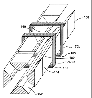
As shown in Fig. 7B, the rods of the central section 154 can be supported by
non-
conductive collars 165 made from a material such as ceramic. Each collar 165
has a
portion that can be metallized to form a conductive ring, 170a or 170b, around
the
circumference of the rod set while remaining electrically isolated from the
rods of the
quadrupole. With an appropriately biased DC potential on each ring 170a, 170b,
discrete
voltage barriers can be created within the central section 154 because a small
fraction of
the electric field created by the rings 170a, 170b penetrates inside the
central section 154.
In operation, these barriers are applied after the trap has been filled in
order to create a
second potential well in a region 180 between the rings 170a and 170b. Ions
are now
prevented from leaving and entering this region 180, which provides a trapped
ion
compartment within the central section. The apertures 160 are shortened, or
the detector is
preferably shortened and/or shielded so as to count only those ions emanating
from region
180. In this manner, any isolated ion populations that arise from random
voltage gradients
along the length of the trap are prevented from interfering with the mass
scan, thereby
minimizing the artifact phenomenon.
It will be appreciated that the compartment from which the trapped ions are
ejected
can alternately be the region defined between the entrance section 152 and the
upstream
ring 170a, or the region defined between the end section 156 and the
downstream ring
170b. It will also be appreciated that while a triple quadrupole instrument
has been
presented and described, the invention can be used in a system where the rod
sets
upstream of the ion trap are omitted and an ion source is directly coupled to
the combined
ion trap/mass analyzer rod set. Similarly, those skilled in the art will
appreciate that many
modifications and variations may be made to the embodiments described herein
without
departing from the spirit of the invention.