Note: Descriptions are shown in the official language in which they were submitted.
CA 02486363 2004-11-17
WO 03/099108 PCT/US03/16618
MINIMALLY INVASIVE TREATMENT SYSTEM FOR AORTIC ANEURYSMS
Field of the Invention
The present invention relates to vascular surgical devices. More
specifically, it relates to endoluminal prostheses for the repair of vascular
defects, such as aortic aneurysms.
Background of Invention
Standard treatment for aortic aneurismal disease involves replacement
of the diseased portion of the aorta with a synthetic graft via an open
surgical
approach. Surgery for abdominal aortic aneurysm (AAA) repair involves a
midline abdominal or retroperitoneal incision to gain access, with significant
organ and bowel dislocation and manipulation necessary to reach the aorta
along the spine. For thoracic aortic aneurysm (TAA) repair, an approach is
generally made from the patient's left chest, often necessitating left lung
and
kidney displacement and possibly involving the removal of one or more ribs to
gain adequate access. In either case, the affected portion of aorta is opened,
debris removed, and bypassed with a prosthetic graft. The repair is generally
viewed as durable and is the "gold standard" of treatment.
The treatment of aortic aneurysms is changing due to the innovation of
minimally invasive therapy. Endovascular treatment for aortic aneurysms, in
contrast to standard open surgical repair, requires only small, bilateral
groin
CA 02486363 2004-11-17
WO 03/099108 PCT/US03/16618
-2-
incisions to access the external iliac or common femoral arteries. This offers
the promise of reduced operative time, associated risk, recovery time, and
blood loss, as well as completion without the use of general anesthetic.
There are two devices currently available in the United States for such
treatment, the Ancure Endograft System and the AneuRx Stent Graft System,
marketed by Guidant (Menlo Park, CA) and Medtronic AVE (Santa Rosa, CA),
respectively. Numerous other devices are available overseas, and in FDA-
approved investigational device exemption (IDE) trials in the U.S. As
summarized by the extensive EUROSTAR Registry, endovascular treatment
can provide lower acute morbidity and mortality compared to an open surgical
approach, allowing for reduced ICU time as well as earlier ambulation and
discharge.
In general, an endovascular stent graft consists of a stent (frame)
component and a graft (fabric) component. A device for AAA treatment may be
tubular (aorto-aortic or aorto mono-iliac) or bifurcated (aorto bi-iliac). The
stent
graft may be modular (i.e., with the body and limbs deployed separately,
having
the ability to be adjusted in vivo with add-on pieces) or unibody (i.e., one
piece)
in design. For TAA treatment, devices are tubular (aorto-aortic). Stent grafts
may be self-expanding (i.e., it expands spontaneously when released from its
delivery system), balloon expandable (i.e., requiring adjunct internal
pressure to
expand it), or they may be a combination of these two.
The metallic stent frame component is intended to support the device,
maintain its physical configuration, and provide an opening force upon
deployment. The stent structure is often integral in maintaining the position
of
the device within the vasculature and providing for its sealing to the vessel.
The stent component may be formed of stainless steel, other similar metal, or
an alloy, such as NITINOL.
The polymeric graft component is the artificial blood vessel (conduit),
designed to provide a path through which blood is re-directed, thereby
excluding the aneurysmal segment of the vessel from blood pressure and flow.
This reduces the propensity of the aneurismal segment to rupture. The graft
component is usually formed of a woven or knitted polyester (PET) or
CA 02486363 2004-11-17
WO 03/099108 PCT/US03/16618
-3-
expanded polytetrafluoroethylene (ePTFE). For delivery into and deployment
within the vasculature, the stent graft is loaded into a delivery system, such
as
a catheter-based device that can be guided to the desired site and that can
then release the stent graft into position under fluoroscopic guidance.
An endovascular stent graft that is designed for permanent implantation
inside the human body must be able to withstand the environment in which it
will reside. It is assumed that the stent graft needs to maintain its full
functionality over time, as the disease process does not "get better" by
placement of the device. Therefore, theoretically, a stent graft must
indefinitely
maintain its physical, chemical, and mechanical properties while being
subjected to the environmental factors of the human aorta. The simulation of
the aortic environment is in itself a challenging endeavor, and one not
completely understood.
No durability test can simulate an infinite time period, so in order to
provide an attainable goal the FDA requires demonstration of a ten-year
service life for cardiovascular implants. The predictable, cyclic
displacements
within the body to which the device may be exposed include the beating of the
heart and the expansion and contraction of the lungs. A proposed device must
withstand approximately 420,000,000 cardiac cycles and 63,000,000
respiratory cycles, taking the average human heart rate as 30 beats per minute
and the average respiratory rate as 12 breaths per minute. Study of human
anatomy and physiology leads to the conclusion that cardiac cycles should
impart radial, torsional, and, to a lesser extent, axial, loading on the
region of
the aorta where an endovascular repair would be completed, while respiratory
cycles should impart axial, bending, and possibly torsional loading.
Summary of the Invention
The present invention relates to an endoluminal prosthesis that
comprises a radially expandable tubular segment having a first end, a second
end, a lumen interconnecting the first end and the second end, and a
connection portion defining an opening in the tubular segment in fluid
communication with the lumen. The connection portion includes a converging
CA 02486363 2004-11-17
WO 03/099108 PCT/US03/16618
-4-
portion, an annular diverging portion, and an annular neck portion
interconnecting the converging portion and the diverging portion.
In accordance with another aspect of the present invention, the
endoluminal prosthesis can comprise a second radially expandable tubular
segment. The second segment can have a first end, a second end, a lumen
interconnecting the first end and the second end, and a second connection
portion defining an opening in a mid-portion of the second tubular segment
between the first end and the second end of the second segment. The opening
in the mid-portion can be in fluid communication with the lumen of the second
segment. The second connection portion can be capable of joining with the
first connection portion in sifu to form a mechanical junction that allows
fluid
flow between the first segment and the second segment.
In accordance with yet another aspect of the present invention, the
endoluminal prosthesis can be used to treat an infrarenal abdominal aortic
aneurysm or a suprarenal abdominal aortic aneurysm. Where the endoluminal
prosthesis is used to treat a suprarenal abdominal aortic aneurysm, the
endoluminal prosthesis can include a radially expandable tubular trunk
segment having a first end, a second end, a lumen interconnecting the first
end
and the second end, and at least two connection portions defining openings in
a mid-portion of the trunk segment between the first end and the second end of
the trunk segment. The openings in the mid-portion can be in fluid
communication with the lumen of the trunk segment. At least one of the
connection portions can comprise an annular converging portion, an annular
diverging portion and an annular neck portion interconnecting the converging
portion and the diverging portion.
The endoluminal prosthesis used to treat a suprarenal abdominal aortic
aneurysm can also comprise a radially expandable tubular branch segment.
The branch segment can have a first end, a second end, a lumen
interconnecting the first end and the second end, and a second connection
portion. The second connection portion being capable of joining with at least
one of the connection portions of the trunk segment in situ to form a
CA 02486363 2004-11-17
WO 03/099108 PCT/US03/16618
-5-
mechanical junction that allows fluid flow between the trunk segment and the
branch segment.
The present invention also provides a method of treating an aortic
aneurysm. According to the inventive method, a first radially expandable
tubular segment can be deployed. The first segment can have a first end, a
second end, a lumen interconnecting the first end and the second end, and a
first connection portion defining an opening in a mid-portion of the first
segment
between the first end and the second end. The first connection portion can
include a converging portion, an annular diverging portion and an annular neck
portion interconnecting the converging portion and the diverging portion. A
second radially expandable tubular segment can also be deployed. The
second segment can include a distal end, a proximal end, a lumen
interconnecting the distal end and the proximal end, and a second connection
portion defining an opening in the proximal end in fluid communication with
the
lumen. The second connection portion can include a converging portion, an
annular diverging portion and an annular neck portion interconnecting the
converging portion and the diverging portion. The second connection portion
and the first connection portion can form an end-to-side junction, which
allows
fluid flow between the first segment and the second segment.
A further aspect of the present invention relates to an endovascular
prosthesis that comprises a radially expandable tubular graft layer having a
first
end, a second end, and a lumen extending between the first end and the
second end. The first end can include a plurality of substantially radially
oriented hooks that extend from the graft layer to provide a fluid tight seal
between graft layer of the first end and a wall of the vasculature. The hooks
can enter the wall of the vasculature in a rotational manner to draw the first
end
into close apposition to the wall. The hooks can extend in a substantially
coplanar configuration that is essentially perpendicular to blood flow through
the endovascular prosthesis. The hooks can be deployed in an essentially
geometric plane that is essentially perpendicular to the blood flow within the
vasculature.
CA 02486363 2004-11-17
WO 03/099108 PCT/US03/16618
-6-
In accordance with another aspect of the present invention the
endovascular prosthesis can comprise a radially expandable tubular graft layer
having a first end, a second end, and a lumen extending along an axis between
the first end and the second end. The first end can include an anchoring
means for substantially inhibiting axially motion of the endovascular
prosthesis
relative to the vasculature and a sealing means to provide a fluid tight seal
between graft layer of the first end and a wall of the vasculature. The
anchoring means and sealing means can be separate from one another.
In a further aspect of the present invention, the sealing means can
comprise a plurality of substantially radially oriented hooks. The hooks can
be
curved to enter a wall of a vasculature upon axial rotation of the
endovascular
prosthesis and draw the first end into close apposition to the wall so as to
form
a fluid tight seal between the graft layer of the first end and the wall of
the
vasculature. The anchoring means can include a second plurality of hooks,
which can penetrate the of wall the vasculature. The hooks of the anchoring
means can be deployed at an angle less than~90 degrees with the direction of
blood flow through the endovascular prosthesis.
Another aspect of the present invention provides a method of deploying
the endovascular prosthesis within a vasculature. According to the inventive
method, an endovascular prosthesis can be provided that includes a radially
expandable tubular graft layer having a first end, a second end, a lumen
extending between the first end and the second end. A plurality of
substantially
radially oriented hooks can extend from the first end. The hooks can be curved
to enter a wall of the vasculature upon axial rotation of the endovascular
prosthesis. The substantially radially oriented hooks of the first end can be
rotationally embedded into the wall of the vasculature to achieve a fluid-
tight
seal.
A further aspect of the present invention relates to a method of forming a
fluid tight seal between an endovascular prosthesis and a wall of a
vasculature.
According to the inventive method, an endovascular prosthesis can be provided
that includes a radially expandable tubular graft layer having a first end, a
second end, a lumen extending between the first end and the second end. A
CA 02486363 2004-11-17
WO 03/099108 PCT/US03/16618
-7-
plurality of substantially radially oriented hooks can extend from the first
end.
The hooks can be curved to enter a wall of the vasculature upon axial rotation
of the endovascular prosthesis. The substantially radially oriented hooks of
the
first end can be rotationally embedded into the wall of the vasculature.
Brief Description of the Drawings
The foregoing and other features of the present invention will become
apparent to those skilled in the art to which the present invention relates
upon
reading the following description with references to the accompanying
drawings, in which:
Fig. 1 is a perspective view of an endoluminal prosthesis in accordance
with an aspect of the present invention;
Fig. 2 is a perspective view of the aortic module of the endoluminal
prosthesis of Fig. 1;
Fig. 3 is a perspective view of the bi-iliac module of the endoluminal
prosthesis of Fig. 1 in accordance with an aspect of the invention;
Fig. 4 is a perspective view of the bi-iliac module of the endoluminal
prosthesis of Fig. 1 in accordance with another aspect of the present
invention;
Figs. 5a-5d Illustrate a method of deploying the endoluminal prosthesis
of Fig. 1 to treat an abdominal aortic aneurysm;
Fig. 6 is a perspective view of the proximal sealing collar module of an
endoluminal prosthesis in accordance with another aspect of the present
invention;
Fig. 7 is a perspective view of an aortic module in accordance with
another aspect of the present invention;
Fig. 8 is a perspective view of the proximal sealing collar of Fig. 6, the
aortic main body module of Fig. 7, and the bi-iliac module of Fig. 3 implanted
in
an abdominal aortic aneurysm;
Fig. 9 is a perspective view of a suprarenal module of an endoluminal
prosthesis in accordance with another aspect of the invention;
Fig. 10 is a perspective view of a branch module of an endoluminal
prosthesis in accordance with another aspect of the invention;
CA 02486363 2004-11-17
WO 03/099108 PCT/US03/16618
_$-
Fig. 11 is a perspective view of the suprarenal module of Fig. 9, the
branch modules of Fig. 10, and aortic modules of Fig. 2 implanted in a
suprarenal aortic aneurysm;
Fig. 12 is a perspective view of another suprarenal module of an
endoluminal prosthesis in accordance with another aspect of the present
invention; and
Fig. 13 is a perspective view of the suprarenal module of Fig. 12 and
branch modules of Fig. 10 implanted in a suprarenal aortic aneurysm.
Description of the Preferred Embodiments
The present invention relates to an endoluminal prosthesis that can be
used to treat a vascular disorder. The endoluminal prosthesis includes at
least
two segments that can be joined together in situ (as well as in vivo) to form
the
endoluminal prosthesis. At least two of the segments include connection
portions for joining the segments. Each connection portion includes a
converging portion, a diverging portion, a neck portion that interconnects the
converging portion and the diverging portion. The connection portions can
engage one another to form a mechanical junction. The endoluminal
prosthesis formed by joining the segments can be used to treat an aortic
aneurysm that extends to or into branching arteries of the aorta.
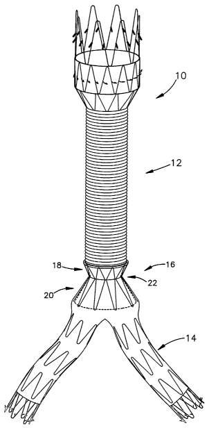
Figs. 1-4 illustrate a perspective view of an endoluminal prosthesis 10 in
accordance with one aspect of the present invention that can be used to treat
an abdominal aortic aneurysm that extends from a portion of the aorta caudal
the renal arteries to the aorta-iliac junction (i.e., infrarenal abdominal
aortic
aneurysm). The endoluminal prosthesis 10 has a modular design that includes
an aortic module 12 and a bi-iliac module 14. The aortic module 12 and the
bi-iliac module14 can connect at a junction 16. The junction 16 can have an
essentially hourglass shape with a converging portion 18, a diverging
portion 20, and a neck portion 22 that interconnects the converging portion 18
and the diverging portion 20.
Fig. 2 is a perspective view of the aortic module 12. The aortic
module 12 comprises a flexible substantially unsupported, and highly
CA 02486363 2004-11-17
WO 03/099108 PCT/US03/16618
_g_
conformable tubular structure 30. The flexible, substantially unsupported
tubular structure 30 of the aortic module 12 readily conforms to the arterial
system acutely as well as accommodates without significant resistance future
re-modeling of the arteries, which may occur due to factors such as sac
shrinkage and/or arterial disease progression.
The aortic module 12 includes a proximal end 32, a distal end 34, and a
main body portion 36 that interconnects the proximal end 32 and the distal
end 34. The proximal end 32 has a substantially frustoconical shape that is
radially supported at least a portion of the length of the proximal end 32.
The
proximal end 32 provides a fluid-tight seal between the proximal end 32 and
the
aorta in order to create a conduit for blood flow, with full, leak-free
exclusion of
the aortic aneurysm. The distal end 34 serves as a mechanical junction (i.e.,
a
docking zone) for the bi-iliac module 14.
The proximal end 32 includes at least one graft layer 38 and a means 40
for radially supporting the graft layer 38. The graft layer 38 comprises a
fabric
having sufficient strength to withstand the surgical implantation of the
aortic
module 12 and to withstand the blood pressure and other biomechanical forces
that are exerted on the proximal end 32. The fabric can be formed by weaving
or extruding a biocompatible material. Examples of biocompatible materials,
which can be weaved or extruded to form the graft layer, are polyethylene,
polypropylene, polyurethane, polyglycolic acid, polyesters, polyamides,
polyfluorocarbons, copolymers thereof, and mixtures thereof. Preferred
biocompatible materials, which can be used to form the graft layer, are
polyesters, such as DACRON and MYLAR, and polyfluorocarbons, such as
polytetrafluoroethylene and expanded polytetrafluoroethylene (ePTFE).
The biocompatible fabric can be an expanded polytetrafluoroethylene
fabric (ePTFE) that is formed, in a manner not shown, by extruding a
polytetrafluoroethylene-lubricant mixture through a ram extruder into a
tubular-
shaped extrudate and longitudinally expanding the tubular extrudate to yield a
uniaxially oriented fibril microstructure in which substantially all of the
fibrils in
the expanded polytetrafluoroethylene (ePTFE) microstructure are oriented
parallel to one another in the axis of longitudinal expansion.
CA 02486363 2004-11-17
WO 03/099108 PCT/US03/16618
-10-
The means 40 for radially supporting the graft layer can comprise a
stent 40. The stent(s) 40 can have a construction similar to any radially
expandable stent well-known in the art, which is suitable for vascular
implantation. For example, the stent 40 can include a plurality of axially
aligned
radially expandable stents. Each stent 40 can include an annular support
beam, which has a generally sinusoidal shape. The wavelength of each of the
support beams can be identical or essentially identical to the wavelength of
the
adjacent axially aligned support beams.
The stent 40 can be formed of a metal that has super-elastic properties.
Preferred metals include nickel-titanium alloys. An example of a nickel-
titanium
alloy is NITINOL. Nickel-titanium alloys are preferred as metals for the stent
40
because of their ability to withstand a significant amount of bending and
flexing
and yet return to their original shape without deformation. Nickel-titanium
alloys are also characterized by their ability to be transformed from one
shape
with an austenitic crystal structure to another shape with a stress induced
martensitic crystal structure at certain temperatures, and to return
elastically to
the one shape with the austenitic crystal structure when the stress is
released.
These alternating crystal structures provide nickel-titanium alloys with their
super-elastic properties. Examples of other metals that have super-elastic
properties are cobalt-chrome alloys (e.g., ELGILOY) and platinum-tungsten
alloys.
Other materials that can be used to form the stent 40 are metals, such
as stainless steel, and polymeric materials, such as nylon, and engineering
plastics, such as thermotropic liquid crystal polymers. Thermotropic liquid
crystal polymers are high molecular weight materials that can exist in a so-
called "liquid crystalline state" where the material has some of the
properties of
a liquid (in that it can flow) but retains the long range molecular order of a
crystal. Thermotropic liquid crystal polymers may be prepared from monomers
such as p,p'-dihydroxy-polynuclear-aromatics or dicarboxy-polynuclear
aromatics.
The stent 40 can be fixedly attached to the inner surface or outer surface
of the graft layer 38 or integrated into the graft layer 38. The stent 40 can
be
CA 02486363 2004-11-17
WO 03/099108 PCT/US03/16618
-11-
attached to the inner surface or outer surface of the graft layer 38 by
mechanical means. An example of a mechanical means is a suture that is
used to sew the stent 40 to the inner surface or outer surface of the graft
layer
38. Alternatively, the stent 40 can be attached to the inner surface or outer
surface of the graft layer 38 by a polymer adhesive layer (not shown).
Examples of polymer adhesive layers include a silicone based layer and
polyurethane based layer.
In yet another configuration (not shown), the proximal end 32 can
include two graft layers that are coaxially aligned and fixedly attached to
one
another by a polymer adhesive layer. The two graft layers can comprise the
same fabric or a different fabric. A means for radially supporting a graft
layer
can be fixedly attached to the inner layer or outer layer of one of the graft
layers.
The proximal end 32 of the aortic module also includes a plurality of
substantially radially oriented hooks 42 for ensuring sealing of the proximal
end 32 of the aortic module 12 within the aorta. Preferably, the hooks 42 are
curved and extend in an outward direction from the proximal end 32 of the
aortic module 12 such that when the proximal end 32 is rotated within the
aorta,
the hooks are deployed, i.e., rotationally embedded, into the wall of aorta,
as
shown in Fig. 5D. Deployment of the radially oriented hooks 42 into the aorta
mimics a surgeon's suture and provides secure apposition of the proximal
end 32 of the aortic module 12 to the aorta. The hooks 42 can extend in a
substantially coplanar configuration that is essentially perpendicular to the
axially extending proximal end and to the blood flow through the proximal end
of the aortic module. The hooks 42 can be deployed in an essentially
geometric plane, which is substantially perpendicular to the blood flow within
the aorta.
An anchoring means 44 can extend from the proximal end 32 of the
aortic module 12. The anchoring means 44 can comprise a radially expandable
bare stent 46. By "bare stent" it is meant that the stent is not covered with
a
graft layer or fabric that would inhibit radial flow of fluid through the
stent. The
CA 02486363 2004-11-17
WO 03/099108 PCT/US03/16618
-12-
bare stent 46 can be substantially tubular and can have a construction similar
to any vascular stent known in the art.
The bare stent 46 can include axially aligned barbs 48 (or hooks) that
extend outwardly from the bare stent 46 and at an angle less 90 degrees with
the direction of blood flow through the proximal end 32. When the bare
stent 46 is radially expanded, the barbs 48 engage the wall of the aorta and
prevent axial migration of the aortic module 12 within the aorta.
The main body portion 36 comprises a highly flexible unsupported
tubular graft material. By "unsupported", it is meant that the main body
portion 36 does not include a support means, such as a stent, to provide
radial
support. Preferably, the main body portion 36 has corrugated construction
formed from radially crimped fabric. The radially crimped fabric includes at
least one graft layer. The fabric used to form the one graft layer can be
similar
to the fabric used to form proximal end 32. Other graft fabrics well known in
the
art can also be used. The radially crimped fabric can also include additional
layers. These additional layers can include other grafts layers and polymer
adhesive layers.
The distal end 34 of the aortic module 12 can include a connection
portion 52 that defines an opening (not shown) in the distal end 34. The
connection portion 52 can have an annular converging portion 54, an annular
diverging portion 56, and an annular neck portion 58 that interconnects the
converging portion 54 and the diverging portion 56. The converging portion 54
and the diverging portion 56 can taper radially inward to the neck portion 58.
The converging portion 54 and diverging portion 56 can both have an
essentially frustoconical shape, which provides the distal end 34 with an
essentially hourglass configuration. As shown in Fig. 5D, the hourglass
configuration allows the distal end 34 of the aortic module 12 to be connected
to the bi-iliac module 14 (Fid. 3) in-situ and form the junction 16 that is
similar to
an end-to-side surgical anastomosis.
The hourglass distal end 34 can be formed from at least one graft layer
60 and a means 62 for radially supporting the graft layer (e.g., annular
stent).
CA 02486363 2004-11-17
WO 03/099108 PCT/US03/16618
-13-
The construction of distal end 34 can be similar to the construction of the
proximal end 32 of the aortic module 12.
Fig. 3 is a perspective view of the one-piece bi-iliac module 14. As
shown in Figs. 5B and 5C, the one-piece bi-iliac module 14 bridges the aortic
bifurcation, extending between an iliac or femoral artery on one side and an
iliac or femoral artery on the other.
Referring again to Fig. 3, the bi-iliac module 14 comprises a flexible
hollow tubular segment 72 that defines a main lumen (not shown) between an
open first end 74 and an open second end 76. The first end 74 and the second
end 76 are in fluid communication with each other by the main lumen of the
segment 72.
The bi-iliac module 14 further includes a connection portion 77 that
defines a side opening 78 in the segment between the first end 74 and second
end 76. The side opening 78 is in fluid communication with the first end 74
and
the second end 76, such that fluid flow will be allowed into the side opening
of
the tubular segment 72 and out of the openings at the first and second ends,
74
and 76.
The side opening 78 can be located about halfway between the two
ends 74 and 76 of the segment. Preferably, the tubular segment 72 has an
inverted U-shape and the side opening 78 is in a mid-portion of the tubular
segment 72 at about the apex of the inverted U-shape.
The connection portion 77 can include an annular converging portion 80,
an annular diverging portion 82, and an annular neck portion 84 that
interconnects the converging portion 80 and the diverging portion 82. The
converging portion 80 and the diverging portion 82 can taper radially inward
to
the neck portion 84. The diverging portion 82 can be essentially frustoconical
(i.e., funnel shaped) in configuration and perpendicularly offset from the
lumen
of the bi-iliac module 14 to provide the connection portion 77 with an
essentially
hourglass configuration. As shown in Fig. 5D, the hourglass connection
portion 77 of the bi-iliac module 14 allows the distal end 34 of the aortic
module 12 to be connected to the bi-iliac module 14 with a mechanical locking
fit.
CA 02486363 2004-11-17
WO 03/099108 PCT/US03/16618
-14-
The diverging portion 82 has a proximal end 90 that defines a first
opening 92 and a distal end 94 that defines a second opening (not shown)
substantially smaller that the first opening 92. The second opening 94 can be
supported in open configuration by a support member, such as a radially
expandable stent. The first opening 92 can be supported in an open
configuration by a resilient ring 96 (e.g., NITINOL or a resilient polymer)
that is
incorporated in the proximal end 90 of the diverging portion 82 at or near the
first opening 92 and a tapered stent 98 that extends along at least a portion
of
the inwardly directed diverging portion 82. The second opening can be
supported in substantially open configuration by a support member, such as a
tapered stent. Optionally, as shown in Fig. 4, the second opening can be
provided without the support member and the first opening can be provided
without the resilient ring.
The bi-iliac module 14 can be formed from at least one graft layer 100
and a means 102 for radially supporting the graft layer 100. The graft layer
100
can comprise a fabric having sufficient strength to withstand the surgical
implantation of the bi-iliac module 14 and to withstand the blood pressure and
other biomechanical forces that are exerted on the bi-iliac module.
The means 102 for radially supporting the graft layer can comprise a
stent 102 that provides lumen patency to the bi-iliac module 14 in the
tortuous
iliac and femoral arteries. The stent(s) 102 can have a construction similar
to
any radially expandable stent well-known in the art, which is suitable for
vascular implantation. The stent 102 can be fixedly attached to the inner
surface or outer surface of the graft layer 100 or integrated into the graft
layer 100. The stent 102 can be attached to the inner surface or outer surface
of the graft layer 100 by mechanical means. Alternatively, the stent 102 can
be
attached to the inner surface or outer surface of the graft layer 100 by a
polymer adhesive layer (not shown). Examples of polymer adhesive layers
include a silicone based layer and polyurethane based layer.
In yet another configuration (not shown), the bi-iliac module can include
two graft layers that are coaxially aligned and fixedly attached to one
another
by a polymer adhesive layer. The two graft layers can comprise the same
CA 02486363 2004-11-17
WO 03/099108 PCT/US03/16618
-15-
fabric or a different fabric. A means for radially supporting a graft layer
can be
fixedly attached to the inner layer or outer layer of one of the graft layers.
The bi-iliac module 14 can be provided with tapering diameter (not
shown) to accommodate the intended iliac or femoral artery sealing location.
The first and second ends, 74 and 76, of the bi-iliac module may also include
bare stents 104 with hooks 106 to secure the device. The bi-iliac module
provides flexibility in sizing the length of the device in-situ, by allowing
the first
and second ends, 74 and 76, of the bi-iliac module to be implanted where
desired for ideal sealing and situating of the mid-portion of the bi-iliac
module 14 in the aorta above the aortic bifurcation.
Figs. 5A-5D illustrate a method of deploying the endoluminal prosthesis
to treat an abdominal aortic aneurysm (AAA) that extends from a portion of the
aorta caudal the renal arteries (RA) to the aorta iliac junction. The method
requires only a single arterial access site.
In the method, it is assumed that the expandable support members and
anchoring means of the endoluminal prosthesis are annular stents, formed from
shape-memory metal, and that the expandable support members and the
anchoring means will radially expand automatically following deployment within
the body. From the method described hereinafter, methods employing balloon
expansion techniques for introducing endoluminal prosthesis in which the
expandable support member and anchoring means do not expand
automatically will be readily apparent to one skilled in the art.
Referring to Figs. 5A-5D, the femoral artery of a leg of the patient to be
treated can be accessed percutaneously or by performing an arteriotomy.
Using conventional fluoroscopic guidance techniques, a first guide wire can be
introduced into the femoral artery. The first guide wire is advanced through
the
ipsilateral iliac artery, the bi-iliac junction of the aorta, and into the
contralateral
iliac artery.
Although the ipsilateral iliac artery and the contralateral iliac artery are
illustrated as being respectively the right iliac artery (RIA) and left iliac
artery
(LIA), the ipsilateral iliac artery can be the left iliac artery and the
contralateral
CA 02486363 2004-11-17
WO 03/099108 PCT/US03/16618
-16-
iliac artery can be the right iliac artery. In this case, the guide wire can
then be
advanced from the left iliac artery to the right iliac artery.
Fig. 5A shows a first delivery system 200, such as a catheter 202
comprising a nosecone 204 and a cartridge sheath 206, which contains the bi-
iliac module 14 in a collapsed condition within the cartridge sheath 204, can
be
advanced over the guide wire 208 through the ipsilateral iliac artery, the
aorta
bifurcation (i.e., bi-iliac junction), and into the contralateral iliac
artery. Proper
placement may be facilitated by use of the radiomarkers (not shown) on the
distal end 210 of the cartridge sheath 206.
Once the distal end 210 of the cartridge sheath 206 is positioned just
beyond the iliac junction the cartridge sheath 206 can be gradually withdrawn
until the bi-iliac module 14 is no longer contained by the cartridge sheath.
Vllith
the cartridge sheath 206 no longer retaining the bi-iliac module 14 in a
collapsed condition, the bi-iliac 14 can radially expand.
Fig. 5B shows that the bi-iliac module 14 can be deployed so that the
first end 74 extends into the ipsilateral iliac artery and the second end 76
extends into the contralateral iliac artery. The connection portion 77 of the
bi-
iliac module is deployed near the apex of bifurcation of the bi-iliac junction
of
the aorta or directly over the bifurcation so that side opening 78 is aligned
with
the aorta.
Once the bi-iliac module 14 is deployed across the bi-iliac junction of the
aorta, a delivery system 250, such as a catheter 252 comprising a
nosecone 254 and a cartridge sheath 256, which contains the aortic module in
a collapsed condition within the cartridge sheath, can be used to deploy the
aortic module across that abdominal aortic aneurysm within the aorta. Fig. 5C
shows that the delivery system 250 containing the aortic module can be
advanced over a guide wire 258 through the ipsilateral iliac artery, through
the
bi-iliac module 14, and into aorta above (i.e., superior) the abdominal aortic
aneurysm (i.e., the delivery system is advanced past the renal arteries (RA)
within the aorta).
Once a distal end 260 of the cartridge sheath 256 is positioned within
the aorta superior the renal arteries, the cartridge sheath 256 can be
gradually
CA 02486363 2004-11-17
WO 03/099108 PCT/US03/16618
-17-
withdrawn until the proximal end 32 of the aortic module 12 is no longer
covered by the cartridge sheath 256. With the cartridge sheath 256 no longer
retaining the aortic module 12 in a collapsed condition, the bare stent 44 and
the expandable support member 40 of the proximal end 32 will radially expand
until bare stent 44 firmly engages the vascular wall of the aorta at the renal
junction and the proximal end 32 firmly contacts the wall of the aorta
inferior the
renal arteries. The proximal end 32 can then be rotated (e.g., about 5
degrees)
to embed the radially oriented hooks into the vascular wall of the aorta.
Embedding the radially oriented hooks 42 into the vascular wall draws the
graft
layer 38 of the proximal end 32 into close apposition to the vascular wall so
as
to form a fluid tight seal between the graft layer 38 of the proximal end 32
and
the wall of the aorta.
The cartridge sheath 256 can then be withdrawn over the distal end 34
of the aortic module 12 so that the cartridge sheath 256 no longer retains the
connection portion 52 in a collapsed condition. Fig. 5D shows that the support
member 62 of the connection portion 52 will radially expand until the outer
surface of the connection portion 52 firmly engages the inner surface of the
connection portion 77 of the bi-iliac module 14 to form the essentially
hourglass
shaped junction 16 which interconnects the aortic module 12 and the bi-iliac
module 14.
Figs. 6-8 illustrate a perspective view of an endoluminal prosthesis 300
in accordance with another aspect of the present invention that can be used to
treat an abdominal aortic aneurysm that extends from a portion of the aorta
caudal the renal arteries to the aorta iliac junction. Referring to Fig. 8,
the
endoluminal prosthesis 300 can include a proximal sealing collar 302, an
aortic
main body module 304, and a bi-iliac module 306. Referring to Fig. 6, the
proximal sealing collar 302 includes a short-length tubular structure 310 that
is
radially supported at least a portion of the length of the tubular structure
310.
The tubular structure 310 includes an annular first end 312 and a
frustoconical
second end 314. The annular first end 312 provides a fluid-tight seal between
the proximal sealing collar 312 and the aorta in order to create a conduit for
blood flow, with full, leak-free exclusion of the aortic aneurysm. The
CA 02486363 2004-11-17
WO 03/099108 PCT/US03/16618
-18-
frustoconical second end 314 securely connects with the aortic module 304 and
provides a mechanical locking mechanism, which prevents modular
disconnection of the frustoconical second end 314 and the aortic module 304.
The tubular structure 310 of the proximal sealing collar 302 includes at
least one graft layer 320 and a means for radially supporting the graft
layer 322. The graft layer 320 comprises a fabric having sufficient strength
to
withstand the surgical implantation of the tubular structure 310 and to
withstand the blood pressure and other biomechanical forces that are exerted
on the structure. The fabric can be formed by weaving or extruding a
biocompatible material.
The means 322 for radially supporting the graft layer can comprise a
stent 322 that provides lumen patency to proximal seal collar 302. The
stent(s)
320 can have a construction similar to any radially expandable stent well-
known in the art, which is suitable for vascular implantation. The stent 322
can
be fixedly attached to the inner surface or outer surface of the graft layer
320 or
integrated into the graft layer 320. The stent 322 can be attached to the
inner
surface or outer surface of the graft layer 320 by mechanical means.
Alternatively, the stent 322 can be attached to the inner surface or outer
surface of the graft layer 320 by a polymer adhesive layer (not shown).
Examples of polymer adhesive layers include a silicone based layer and
polyurethane based layer.
In yet another configuration (not shown), the proximal sealing collar 302
can include two graft layers that are coaxially aligned and fixedly attached
to
one another by a polymer adhesive layer. The two graft layers can comprise
the same fabric or a different fabric. A means for radially supporting a graft
layer can be fixedly attached to the inner layer or outer layer of one of the
graft
layers.
The proximal sealing collar 302 can also include a plurality of
substantially radially oriented hooks 324 for ensuring sealing of the proximal
sealing collar 302 within the aorta. Preferably, the hooks 324 are curved and
extend in an outward direction from the proximal sealing collar 30 such that
when the proximal sealing collar 302 is rotated within the aorta, the hooks
are
CA 02486363 2004-11-17
WO 03/099108 PCT/US03/16618
-19-
deployed, i.e., rotationally embedded, into the aorta, as shown in Fig. 8.
Deployment of the radially oriented hooks 324 into the aorta mimics a
surgeon's suture and provides secure apposition of the proximal sealing
collar 302 to the aorta. The hooks can extend in a substantially coplanar
configuration so that the hooks are deployed in an essentially geometric
plane,
which is substantially perpendicular to the blood flow within the aorta.
Fig. 7 is a perspective view of the aortic module 304 in accordance with
a second embodiment of the present invention. The aortic module 304 in
accordance with this embodiment comprises a flexible substantially
unsupported, and highly conformable tubular structure 330 that connects the bi-
iliac module 302 and the proximal sealing collar 302. The aortic module 304
readily conforms to the arterial system acutely as well as accommodates
without significant resistance future re-modeling of the arteries, which may
occur due to factors such as sac shrinkage and/or arterial disease
progression.
The aortic module 304 includes a proximal end 332, a distal end 334,
and a main body portion 336 that interconnects the proximal end 332 and the
distal end 334. The proximal end 332 and the distal end 334 serve as
mechanical junctions, i.e., docking zones for the proximal sealing collar 302
and the bi-iliac module 306, respectively.
The proximal end 332 has a substantially frustoconical shape that is
radially supported. The frustoconical shape is used to securely connect of the
proximal end 332 of the aortic module 304 within the proximal sealing collar
302 so as to prevent modular disconnection between the proximal sealing
collar 302 and the aortic module 304.
The proximal end 332 includes at least one graft layer and a means 340
for radially supporting the graft layer. The construction of the proximal end
332
of the aortic module 304 can be similar to the construction of the proximal
sealing collar 302.
An anchoring means 350 can extend from the proximal end 332 of the
aortic module 304. The anchoring means 350 can comprise a radially
expandable bare stent 352. The bare stent 352 is substantially tubular and can
have a construction similar to any vascular stent known in the art.
CA 02486363 2004-11-17
WO 03/099108 PCT/US03/16618
-20-
The bare stent 352 can include axially aligned barbs 354 (or hooks) that
extend outwardly from the bare stent 352 and at an angle less 90 degrees with
the direction of blood flow through the proximal end 332. When the bare
stent 352 is radially expanded, the barbs 354 engage the wall of the aorta and
prevent axial migration of the aortic module 304 within the aorta.
The main body portion 336 comprises a highly flexible unsupported
tubular graft material. Preferably, the main body portion 336 has corrugated
construction formed from radially crimped fabric. The radially crimped fabric
includes at least one graft layer. The fabric used to form the one graft layer
can
be similar to the fabric used to form the proximal sealing collar. Other graft
fabrics well known in the art can also be used. The radially crimped fabric
can
also include additional layers. These additional layers can include other
grafts
layers and polymer adhesive layers.
The distal end 334 of the aortic module 304 can include a connection
portion 360 with a radially supported hourglass configuration. The connection
portion can have a construction essentially similar to the construction of the
distal end 52 of the aortic module 12 of the endoluminal prosthesis 10. As
shown in Fig. 8, the hourglass configuration allows the distal end 334 of the
aortic main body module 304 to be connected to the bi-iliac module 306 (Fig.
3)
in-situ and form a junction similar to an end-to-side surgical anastomosis.
Referring to Fig. 8, the bi-iliac module 306 of the endoluminal
prosthesis 300 can have an essentially similar construction as the bi-iliac
module 14 described above and shown in Fig. 3.
The deployment of the endoluminal prosthesis 300 can be achieved in a
manner similar to the deployment of the endoluminal prosthesis 10. For
example, the bi-iliac module can be deployed over the aortic bifurcation,
using
a delivery system, so that a first end 370 of the bi-iliac module 306 extends
into
one iliac artery (IA), a second end 372 of the bi-iliac module extends into
the
other iliac artery (IA), and a side opening 328 is deployed near the apex of
bifurcation or directly into the aorta. The proximal sealing collar 302 can
then
be deployed using a delivery system in the immediate infrarenal portion of the
aorta. The proximal sealing collar module can be sealed to the aorta using the
CA 02486363 2004-11-17
WO 03/099108 PCT/US03/16618
-21-
system of rotationally-deployed hooks. Finally, the aortic main body
module 306 can be deployed to interconnect the proximal sealing collar
module 10 and the bi-iliac module 70, such that the aortic module 304 forms an
overlapping junction with the proximal sealing collar 302 and an overlapping
end-to-side junction with the bi-iliac module 306.
Figs. 9, 10, and 11 illustrate an endoluminal prosthesis 400 in
accordance with yet another aspect of the present invention. The endoluminal
prosthesis can be used to treat an aortic abdominal aneurysm that extends
across the renal artery junction (i.e., suprarenal abdominal aortic aneurysm).
Referring to Fig. 11, the endoluminal prosthesis 400 has a modular design that
includes a suprarenal module 402, four branch modules 404, and two aortic
modules 406. The aortic modules 404 and branch modules 406 can be
connected to the suprarenal module 402 at junctions 410. Each junction 410
can have an essentially hourglass shape and include a converging portion, a
diverging portion and a neck portion interconnecting the converging portion
and
the diverging portion.
Referring to Fig. 9, the suprarenal module 402 includes a flexible tubular
segment that includes a first end 420, a second end 422, and a body
portion 424 that interconnects the first end 420 and the second end 422. The
first end 420 and the second end 422 serve as mechanical junctions for,
respectively, the aortic modules 406 (Fig. 11 ). The first end 420 and the
second end 422 are in fluid communication with each other via a lumen (not
shown) of the suprarenal module 402.
The first end 420 and the second end 422 comprise, respectively,
connection portions 426 and 428. The connection portions 426 and 428 define,
respectively, a first opening 430 in the first end 422 and a second opening
432
in the second end 422. The connection portions 426 and 428 each include an
annular converging portion 440, an annular diverging portion 442, and an
annular neck portion 442 interconnecting the converging portion 440 and the
diverging portion 444. The converging portions 440 and the diverging
portions 442 taper radially inward to the neck portions 444. The converging
portions 440 and diverging portions 442 can have an essentially frustoconical
CA 02486363 2004-11-17
WO 03/099108 PCT/US03/16618
-22-
shape that provides the first end 420 and the second end 422 with an
essentially hourglass configuration.
The body portion 424 includes a first renal connection portion 450, a
second renal connection portion 452, a superior mesenteric connection
portion 454, and a celiac connection portion 456 that define, respectively,
side
openings 460, 462, 464, and 466 in the body portion 424. The side
openings 460, 462, 464, and 466 are in fluid communication with the lumen of
the suprarenal module 402, such that fluid will flow from the lumen and out of
the side openings 460, 462, 464, and 466. As may be seen in Fig. 11, the
connection portions 450, 452, 454, and 456 can be located on body portion 424
such that when the suprarenal module 402 is deployed in the aorta the
connection portions can be aligned respectively with the renal arteries (RA),
the
superior mesenteric artery (SMA), and the celiac artery (CA).
Each connection portion (e.g., 452) can include an annular converging
portion 470, an annular diverging portion 472, and a neck portion 474 that
interconnects the annular converging portion 470 and the annular diverging
portion 472. The converging portion 470 and the diverging portions 472 can
taper radially inward to the neck portions 474. The diverging portions 474 can
be essentially frustoconical in configuration and perpendicularly offset from
the
lumen to provide each connection portion 450, 452, 454, and 456 with an
essentially hourglass configuration. Fig. 11 shows that the essentially
hourglass connection portions 450, 452, 454, and 456 of the suprarenal
module 402 allow the branch modules 404 to be connected to the suprarenal
module 402 with a mechanical locking fit.
The suprarenal module 402 can be formed from at least one graft
layer 480 and a means 482 for radially supporting the graft layer 480. The
graft
layer 480 can comprise a fabric having sufficient strength to withstand the
surgical implantation of the suprarenal module 402 and to withstand the blood
pressure and other biomechanical forces that are exerted on the structure. The
fabric can be formed by weaving or extruding a biocompatible material.
The means 482 for radially supporting the graft layer 480 can comprise
at least one stent 482 that provides lumen patency to suprarenal module 402.
CA 02486363 2004-11-17
WO 03/099108 PCT/US03/16618
-23-
The stent(s) 482 can have a construction similar to any radially expandable
stent well-known in the art, which is suitable for vascular implantation. The
scent 482 can be fixedly attached to the inner surface or outer surface of the
graft layer 480 or integrated into the graft layer 480. The stent 482 can be
attached to the inner surface or outer surface of the graft layer 480 by
mechanical means. Alternatively, the stent 482 can be attached to the inner
surface or outer surface of the graft layer 480 by a polymer adhesive layer
(not
shown). Examples of polymer adhesive layers include a silicone based layer
and polyurethane based layer.
In yet another configuration (not shown), the suprarenal module 402 can
include two graft layers that are coaxially aligned and fixedly attached to
one
another by a polymer adhesive layer. The two graft layers can comprise the
same fabric or a different fabric. A means for radially supporting a graft
layer
can be fixedly attached to the inner layer or outer layer of one of the graft
layers.
Referring to Fig. 10, the branch modules 404 are connected respectively
to the first renal connection portion 450, the second renal connection
portion 452, the superior mesenteric connection portion 454, and the celiac
portion 456. The branch modules 404 interconnect the suprarenal module 402
with branch arteries of the aorta (i.e., the renal arteries, the superior
mesenteric
artery, and the celiac artery). Although the branch modules 404 are
illustrated
as having similar lengths and diameters, the lengths and diameters of the
branch modules 404 can vary depending on the distance from the connection
portions 450, 452, 454, and 456 to the specific artery, which the branch
module 404 connects, and the diameter of the specific branch artery.
Fig. 10 illustrates an exemplary embodiment of a branch module 404.
The branch modules 404 all have a similar construction. Accordingly the
construction of only one of the branch modules 404 will be discussed below.
The branch module 404 comprises a flexible hollow tubular segment 500
that includes a first end 502 and an second end 504. The first end 502 and the
second end 504 are in fluid communication with each other by a main lumen
(not shown) of the branch module 404.
CA 02486363 2004-11-17
WO 03/099108 PCT/US03/16618
-24-
The first end 502 includes a connection portion 506 that defines an
opening 508 in the first end 502. The connection portion 506 can include an
annular converging portion 510, an annular diverging portion 512, and an
annular neck portion 514 that interconnects the converging portion 510 and the
diverging portion 512. The converging portion 510 and the diverging
portion 512 taper radially inward to the neck portion 514. The converging
portion 510 and the diverging portion 512 can be essentially frustoconical
(i.e.,
funnel shaped) in configuration to provide the connection portion 506 with an
essentially hourglass configuration. As shown in Fig. 11, the hourglass
connection portion 512 of branch module 404 allows the first end 502 of the
branch module 404 to be connected to the connection portions of the
suprarenal module 402 with a mechanical locking fit.
The branch module 404 can be formed from at least one graft layer 516
and a means 520 for radially supporting the graft layer 516. The graft layer
516
can comprise a fabric having sufficient strength to withstand the surgical
implantation of the branch module 404 and to withstand the blood pressure and
other biomechanical forces that are exerted on the branch module 404. The
fabric can be formed by weaving or extruding a biocompatible material.
The means 520 for radially supporting the graft layer 516 can comprise
at least one stent 520 that provides lumen patency to the branch module 404.
The stent(s) 520 can have a construction similar to any radially expandable
stent 520 well-known in the art, which is suitable for vascular implantation.
The
stent 520 can be fixedly attached to the inner surface or outer surface of the
graft layer 516 or integrated into the graft layer 520. The stent 520 can be
attached to the inner surface or outer surface of the graft layer 520 by
mechanical means. Alternatively, the stent 520 can be attached to the inner
surface or outer surface of the graft layer 516 by a polymer adhesive layer
(not
shown). Examples of polymer adhesive layers include a silicone based layer
and polyurethane based layer.
In yet another configuration (not shown), the branch module 404 can
include two graft layers that are coaxially aligned and fixedly attached to
one
another by a polymer adhesive layer. The two graft layers can comprise the
CA 02486363 2004-11-17
WO 03/099108 PCT/US03/16618
-25-
same fabric or a different fabric. A means for radially supporting a graft
layer
can be fixedly attached to the inner layer or outer layer of one of the graft
layers.
Optionally, the second end 504 of the branch module 404 can be
provided with tapering diameter (not shown) to accommodate the intended
branch artery sealing location. The second end 504 of the branch module can
also include a bare stent 430 with hooks 432 (or barbs) to secure the branch
module 404 within the vasculature.
The aortic modules 406 of the endoluminal prosthesis 400 can have an
essentially similar construction as the aortic module 12 described above and
shown in Fig. 2. The lengths and diameters of the aortic modules 406,
however, can vary depending on the distance from the connection portions the
length and diameter of the aneurysm that extend across the renal artery
junction.
The endoluminal prosthesis 400 can be deployed by implanting the
aortic module 406 in a suprarenal portion of the aorta (e.g., using a delivery
system, such as a catheter with a nosecone and a cartridge sheath). Following
implantation of the aortic module 406, the suprarenal module 406 can be
deployed (e.g., using a delivery system) across the abdominal aortic aneurysm
(AAA). The suprarenal module 402 can be connected to the suprarenal aortic
module 406 with a mechanical locking fit. A second aortic module 406 can
then be deployed (e.g., using a delivery system) caudal the abdominal aortic
aneurysm. The second aortic module can be connected to the suprarenal
module 402 with a mechanical locking fit. The branch modules 404 can then
be individually deployed (e.g., using a delivery system) through the
suprarenal
module 402 and to the branch arteries (RA), (SMA), and (CA). The branch
modules 404 can be connected to the suprarenal module 402 with a
mechanical locking fit. It will be appreciated by one skilled in the art based
on
the methods described above with respect to deployment of the endoluminal
prosthesis 10, that the endoluminal prosthesis 400, like the endoluminal
prosthesis 10, can be deployed using only unilateral arterial access.
CA 02486363 2004-11-17
WO 03/099108 PCT/US03/16618
-26-
Figs. 12 and 13 illustrate an endoluminal prosthesis 600 in accordance
with yet another aspect of the present invention. The endoluminal
prosthesis 600 can be used to treat an aortic abdominal aneurysm that extends
across the renal artery junction. Referring to Fig. 13, the endoluminal
prosthesis 600 has a modular design that includes a suprarenal module 602
and four branch modules 604. The branch modules 604 can be connected to
the suprarenal module 602 at junctions 606. Each junction 606 can have an
essentially hourglass shape and include a converging portion, a diverging
portion and a neck portion interconnecting the converging portion and the
diverging portion.
Referring to Fig. 12, the suprarenal module 602 includes a first end 610,
a second end 612, and a body portion 614 that interconnects the first end 610
and the second end 612. The first end 610 and the second end 612 are in fluid
communication with each other via the lumen (not shown) of the suprarenal
module 602.
The first end 610 and the second end 612 include substantially
frustoconical portions 620 and 622, which are radially supported at least a
portion of the length of the frustoconical portions 620 and 622 and highly
flexible unsupported tubular portions 624 and 626. The first end 610 and the
second end 612 provide a fluid-tight seal with the aorta and create a conduit
for
blood flow, with full, leak-free exclusion of the aortic aneurysm.
The frustoconical portions 620 and 622 of the first end 610 and the
second end 612 can be formed from at least one graft layer 630 and a
means 632 for radially supporting the graft layer 630. The graft layer 630 can
comprise a fabric having sufficient strength to withstand the surgical
implantation of the suprarenal module 602 and to withstand the blood pressure
and other biomechanical forces that are exerted on the suprarenal module 602.
The fabric can be formed by weaving or extruding a biocompatible material.
The means 632 for radially supporting the graft layer 630 can comprise
at least one stent 632 that provides lumen patency to the suprarenal
module 602. The stent(s) 632 can have a construction similar to any radially
expandable stent 632 well-known in the art, which is suitable for vascular
CA 02486363 2004-11-17
WO 03/099108 PCT/US03/16618
-27-
implantation. The stent 632 can be fixedly attached to the inner surface or
outer surface of the graft layer 630 or integrated into the graft layer 630.
The
stent 632 can be attached to the inner surface or outer surface of the graft
layer 630 by mechanical means. Alternatively, the stent 632 can be attached to
the inner surface or outer surface of the graft layer 630 by a polymer
adhesive
layer (not shown). Examples of polymer adhesive layers include a silicone
based layer and polyurethane based layer.
In yet another configuration (not shown), the frustoconical portions 620
and 622 can include two graft layers that are coaxially aligned and fixedly
attached to one another by a polymer adhesive layer. The two graft layers can
comprise the same fabric or a different fabric. A means for radially
supporting
a graft layer can be fixedly attached to the inner layer or outer layer of one
of
the graft layers.
The frustoconical portions 620 and 622 of the first end 610 and the
second end 612 can each include pluralities of substantially radially oriented
hooks 640 for ensuring sealing of the first end 610 and the second end 612
within the aorta. Preferably, the hooks 640 are curved and extend in an
outward direction from the first end 610 and the second end 612 such that
when the first end 610 and the second end 612 are rotated within the aorta,
the
hooks are deployed, i.e., rotationally embedded, into the wall of aorta, as
shown in Fig. 13. Deployment of the radially oriented hooks 640 into the aorta
mimics a surgeon's suture and provides secure apposition of the first end 610
and the second en 612 to the aorta. The hooks 640 can extend in a
substantially coplanar configuration that is essentially perpendicular to the
axially extending proximal end and to the blood flow through the proximal end
of the aortic module. The hooks 640 can be deployed in an essentially
geometric plane, which is substantially perpendicular to the blood flow within
the aorta.
The tubular portions 624 and 626 can have a corrugated construction
formed from radially crimped fabric. The radially crimped fabric includes at
least one graft layer 634. The fabric used to form the one graft layer can be
similar to the fabric used to form proximal end. Other graft fabrics well
known
CA 02486363 2004-11-17
WO 03/099108 PCT/US03/16618
-28-
in the art can also be used. The radially crimped fabric can also include
additional layers. These additional layers can include other grafts layers and
polymer adhesive layers.
Anchoring means 650 can extend from the first end 610 and the second
end 612 of the suprarenal module 602. The anchoring means 650 can
comprise radially expandable bare stents 652. The bare stents 652 can be
substantially tubular and can have a construction similar to any vascular
stent
known in the art.
The bare stents 652 can includes axially aligned barbs 654 (or hooks)
that extend outwardly from the bare stent 652 and at an angle less 90 degrees
with the direction of blood flow through the suprarenal module 602. When the
bare stent 652 is radially expanded, the barbs 654 engage the wall of the
aorta
and prevent migration of the suprarenal module 602 within the aorta.
The body portion 614 includes a first renal connection portion 660, a
second renal connection portion 662, a superior mesenteric connection
portion 664, and a celiac connection portion 666, which each define side
openings in the body portion. The side openings are in fluid communication
with the lumen, such that fluid will flow from the lumen and out of the side
openings. The connection portions 660, 662, 664, and 666 can be located on
the body portion 614 such that when the suprarenal module 602 is deployed in
the aorta the connection portions 660, 662, 664, and 666 can be aligned
respectively with the renal arteries, the superior mesenteric artery, and the
celiac artery.
Each connection portion (e.g., 662) can include an annular converging
portion 670, an annular diverging portion 672, and a neck portion 674 that
interconnects the annular converging portion 670 and the annular diverging
portion 672. The converging portions 670 and the diverging portions 672 can
taper radially inward to the neck portions 674. The converging portions 670
and the diverging portions 672 can be essentially frustoconical in
configuration
and perpendicularly offset from the lumen to provide each connection
portion 660, 662, 664, and 666 with an essentially hourglass configuration.
Fig. 13 shows that the essentially hourglass connection portions 660, 662,
664,
CA 02486363 2004-11-17
WO 03/099108 PCT/US03/16618
-29-
and 666 of the suprarenal module 602 allow the branch modules to be
connected to the suprarenal module with a mechanical locking fit.
The body portion 614 of the suprarenal module 602 can be formed from
at least one graft layer 680 and a means 682 for radially supporting the graft
layer 680. The graft layer 680 can comprise a fabric having sufficient
strength
to withstand the surgical implantation of the suprarenal module 602 and to
withstand the blood pressure and other biomechanical forces that are exerted
on the structure. The fabric can be formed by weaving or extruding a
biocompatible material.
The means 682 for radially supporting the graft layer 680 can comprise
at least one stent 682 that provides lumen patency to the body portion 614 of
the suprarenal module 602. The stent(s) 682 can have a construction similar to
any radially expandable stent well-known in the art and which is suitable for
vascular implantation. The stent 682 can be fixedly attached to the inner
surface or outer surface of the graft layer 680 or integrated into the graft
layer 680. The stent 682 can be attached to the inner surface or outer surface
of the graft layer 680 by mechanical means. Alternatively, the stent 682 can
be
attached to the inner surface or outer surface of the graft layer 680 by a
polymer adhesive layer (not shown). Examples of polymer adhesive layers
include a silicone based layer and polyurethane based layer.
In yet another configuration (not shown), the body portion 614 of the
suprarenal module 602 can include two graft layers that are coaxially aligned
and fixedly attached to one another by a polymer adhesive layer. The two graft
layers can comprise the same fabric or a different fabric. A means for
radially
supporting the graft layer can be fixedly attached to the inner layer or outer
layer of one of the graft layers.
Referring to Fig. 13, the branch modules are connected respectively to
the first renal connection portion 660, the second renal connection portion
662,
the superior mesenteric connection portion 664, and the celiac portion 666.
The branch modules 604 interconnect the suprarenal module 602 with branch
arteries of the aorta (i.e., the renal arteries, the superior mesenteric
artery, and
the celiac artery).
CA 02486363 2004-11-17
WO 03/099108 PCT/US03/16618
-30-
The branch modules 604 of the endoluminal prosthesis 600 can have an
essentially similar construction as the branch modules 404 described above
and shown in Fig. 10. Although the branch modules 604 are illustrated as
having similar lengths and diameters, the lengths and diameters of the branch
modules 604 can vary depending on the distance from the connection
portions 660, 662, 664, and 666 to the specific artery, which the branch
module 604 connects, and the diameter of the specific branch artery.
The endoluminal prosthesis 600 can be deployed by implanting the
suprarenal module 602 across the abdominal aortic aneurysm (AAA) (e.g.,
using a second delivery system, such as a catheter with a nosecone and a
cartridge sheath). The branch modules 604 can then be individually deployed
(e.g., using a delivery system) through the suprarenal module 602 and to the
branch arteries (RA), (SMA), and (CA). The branch modules 604 can be
connected to the suprarenal module 602 with a mechanical locking fit to form
junctions 606. It will be appreciated by one skilled in the art based on the
methods described above with respect to deployment of the endoluminal
prosthesis 10, that the endoluminal prosthesis 600, like the endoluminal
prosthesis 10, can be deployed using only unilateral arterial access.
From the above description of the invention, those skilled in the art will
perceive improvements, changes and modification. Such improvements,
changes and modifications within the skill of the art are intended to be
covered
by the appended claims. For example, the hooks of the proximal sealing collar,
the aortic module, the bi-iliac module, the suprarenal module, andlor the
branch
modules can have a barbed end configuration similar to a fishhook to prevent
dislodgement from the artery wall. The barbed end preferably employs a
rough-textured surface to promote a heightened localized response and
increased scar tissue formation. Heightened localized response and increased
scar tissue formation further enhances the fixation of the hooks within the
wall
of the aorta. The rough textured surface on the barbed hooks can be provided
by various methods. Examples of methods that can be used to provide a rough
textured surface on a hook include selective metallic coating of a metallic
hook,
micro-bead blasting a hook, injection molding a hook from a polymer material
CA 02486363 2004-11-17
WO 03/099108 PCT/US03/16618
-31-
with the desired roughness, and forming a hook of multiple materials and
dissolving away one or more of the materials.
In yet another aspect of the present invention, at least one of the
modules can have varying biological, physical, and/or chemical properties
associated with the inner and/or outer surface of the module such that the
inner
surface of the module is optimized to reduce biological responses and/or the
outer surface is optimized to promote biological responses. Examples of
variations in the physical properties include the inner surface of at least
one
module being smooth to lessen clotting or other,solid particle deposition
and/or
the outer surface of at least one module being rough to increase the surface
area for foreign material and increase biologic host response. Examples of
variations in the chemical properties include the inner surface of at least
one
module incorporating an anti-thrombogenic agent, such as heparin, to decrease
the propensity for clot formation and/or the outer surface incorporating a
thrombogenic agent, such as thrombin, to increase the propensity for clot
formation.