Note: Descriptions are shown in the official language in which they were submitted.
CA 02487138 2004-11-24
WO 03/102553 PCT/GB03/02341
GAS SENSORS
FIELD OF THE INVENTION
This invention relates to apparatus for, and methods
of, sensing gasses. The invention particularly relates to
such methods and devices in which optical radiation is
transmitted through a gas and subsequently detected to
provide information concerning the gas.
BACKGROUND OF THE INVENTION
In a typical gas monitor, an infrared source is
arranged to emit radiation, which passes through a gas to
be monitored. Infrared radiation is absorbed by the gas
and that remaining is subsequently detected by an infrared
detector, such as a photodiode, thermopile or pyroelectric
detector. A comparison is made between the source
intensity and the intensity of radiation detected
following passage through the gas to give the
concentration of a target gas. The concentration is
related to the intensity by the following equation:
-EC1
I=Ioe
where I is the intensity of radiation detected by the
detector, is the intensity of radiation emitted at the
source, E is effectively a constant which is dependent on
the particular gas being monitored, c is the gas
concentration and 1 is the distance travelled by the
radiation through the gas.
CA 02487138 2004-11-24
WO 03/102553 PCT/GB03/02341
2
The present invention seeks to provide a gas monitor
having improved characteristics over those previously
known.
S SUMMARY OF THE INVENTION
The invention is defined in the claims, to which
reference is now directed.
An embodiment of the invention provides a gas sensor
comprising a chamber arranged to admit gas, an optical
source and detector means sensitive to light from the
source, the detector means including a filter. Surface
portions of ellipsoidal curvature are arranged to reflect
light from the light source to the detector. The detector
means is arranged to detect light from a predetermined
directional range, so that only light reflected by the
surface portions of ellipsoidal curvature reaches the
detector.
The provision of a directional detector improves
performance of the sensor, because the performance of the
filter is much improved when receiving radiation from a
predetermined directional range, for example a narrow
2$ solid angle centred at normal incidence. The use of a
directional detector in conjunction with reflection from
ellipsoidal surfaces ensures that light from the source to
the detector travels a path of substantially constant
length, and that light reflected in any other way reaching
the sensor is minimised. The sensor can be configured so
that the detector collects radiation that has travelled
predetermined optical paths. Thus, little of the radiation
reaches the detector by means of undesired optical paths,
thereby improving the signal-to-noise ratio of the sensor
and leading to a more accurate determination of gas
concentration, particularly at low levels.
CA 02487138 2004-11-24
WO 03/102553 PCT/GB03/02341
3
Preferably, the source is configured to emit optical
radiation in a predetermined directional range, such as a
narrow solid angle at near normal incidence.
The provision of a directional source enables the
sensor to be configured so that a large proportion of
radiation is directed towards the detector along
predetermined optical paths. Thus, even less of the
radiation is scattered, or reaches the detector by other
optical paths, further improving the signal-to-noise ratio
of the sensor.
Advantageously, the directional ranges, such as the
solid angles, are co-axial with the axis of the source and
detector respectively.
The invention is particularly useful when employed in
a gas sensor described by our British patent No.2316172.
This patent describes a gas sensor comprising a housing
containing an infrared source and a detector, which are
placed at the foci of respective ellipsoidal surfaces.
Truncated ellipsoids provide a folded optical path for
radiation from the source. Employing the present invention
in such a gas sensor reduces the amount of light
travelling other than by a desired folded optical path.
The chamber may further include gas admittance means.
The detector and source may be located in a cylindrical
housing having end walls. Regions of an end wall of the
housing, and possibly adjacent regions of the cylinder may
provide gas admittance means.
The end wall may include a reflector for the chamber,
occupying a central region of the end wall, with the gas
admittance means occupying the periphery of the wall.
CA 02487138 2004-11-24
WO 03/102553 PCT/GB03/02341
4
The optical source is preferably an infrared source
but sources and detectors operating in other parts of the
optical spectrum may be used in other embodiments.
BRIEF DESCRIPTION OF THE FIGURES
An embodiment of the invention will now be described,
by way of example, with reference to the accompanying
drawings, in which:-
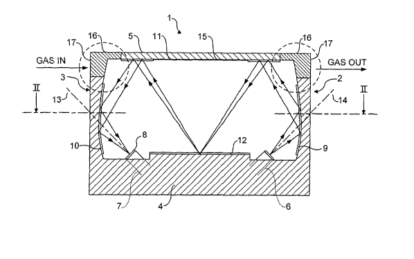
Figure 1 is a sectional schematic view of a gas
sensor constructed according to the invention;
Figures la and lb illustrate alternative embodiments
of the gas admittance regions of the sensor of Figure
1;
Figure 2 is a plan view through II-II of Figure 1;
Figure 3 shows the geometry of ellipsoidal curvature
of the gas sensor of Figure 1;
Figure 3a shows the source or detector in greater
detail;
Figure 4 shows an alternative arrangement of
ellipsoidal surface to include reflections for a main
sensor and a reference sensor;
Figure 5 shows the geometry of ellipsoidal curvature
of the gas sensor of Figure 4;
CA 02487138 2004-11-24
WO 03/102553 PCT/GB03/02341
Figures 6a-d show various arrangements of the upper
end wall 5; and
Figure 7 shows a further alternative arrangement of
reflection surfaces incorporating a longer light path
S and further reflections.
DESCRIPTION OF A PREFERRED EMBODIMENT
With reference to Figures 1 and 2, a gas sensor is
shown and indicated generally by the reference numeral 1.
The detector comprises a housing 2, which is preferably
flameproof. The housing 2 comprises a generally
cylindrical wall 3 with end walls 4 and 5. The housing 2
1S contains a source 6 of infrared radiation, mounted in one
of the end walls 4. The housing also contains an infrared
detector 7, which includes a bandpass filter 8, also
mounted in the end wall 4. Portions 9 to 12 inclusive of
the interior surfaces of the housing 2 are reflectors of
infrared radiation. The filter 8 is arranged to be
transparent to the strong fundamental absorption band of
the gas being detected.
A constraint for gas sensors of the type described is
2S the need to be small, typically an industry standard size
of housing 2 of diameter 20mm and depth l5mm, whilst
retaining as long an optical path length from source to
detector as possible. Another industry standard size to
which the invention could equally apply is 32mm diameter.
The long optical path length is needed to ensure best
sensitivity for gases of low concentrations. The longer
the path length, the greater the effect on attenuation of
light at the absorption band of the gas and hence the
better the signal to noise ratio. However, we have also
3S appreciated that the path length should be substantially
CA 02487138 2004-11-24
WO 03/102553 PCT/GB03/02341
6
constant for all light transmitted from the source to the
detector. If light is able to travel through differing
path lengths, then any change in intensity on introduction
of the gas to be analysed will differ depending upon the
path length. As a result, the variation due to the gas to
be analysed in comparison to variation due to other
factors, such as other gases or errors due to temperature
changes, will be reduced. This effectively worsens the
signal to noise ratio. In the embodiment shown, the path
length is around 40mm.
In accordance with a first aspect of the invention,
the detector 7 is directional, i.e. it is arranged to
detect radiation incoming from a predetermined directional
range. Preferably, the directional range comprises a
predetermined solid angle, which may be centred on the
axis 13 of the detector.
In conjunction with the two ellipsoidal surface
portions, this ensures that light from the source to the
detector within the limited range of angles all travels
the same path length. This fact can be proven according
to the geometry, but can be seen empirically with
reference to Figure 3. Light from the source 3 is
reflected from a surface portion 9 being shaped as a
portion of all ellipsoid "a". This light is focused
toward a point 30, but reflected back from a planar
reflective portion of the inner surface of the wall 5 and
focussed to a planar reflective region 12. The reflective
region 12 is effectively at an image of the plane 31
containing the focus point 30 of the ellipsoids "a" and
"b". This "folded" arrangement reduces the height of the
sensor by roughly half whilst maintaining the path length.
From the focus point 32 light is reflected via a further
reflective region of wall 5 to a second reflective portion
10 of ellipsoidal shape defined by ellipsoid "b" and
CA 02487138 2004-11-24
WO 03/102553 PCT/GB03/02341
7
focussed to the detector shown schematically at 7. Thus,
a comparatively long path length is achieved within a
housing of small dimension. In particulr, the path length
for light from the source to the detector is substantially.
constant and unwanted reflections are avoided.
This arrangement also ensures that the detector
collects radiation from a narrow cone of light, the solid
angle being typically 10-12°. It has been found that the
bandpass characteristic of the filter 8 associated with
the detector is better defined when radiation impinges on
it from predetermined directions, and preferably at near-
normal incidence.
The source 6 is also directional i.e. is arranged to
emit radiation in a predetermined directional range.
Preferably, the directional range comprises a solid angle,
which may be centred on the axis 14 of the source 6. This
arrangement of the source ensures that the optical
radiation it emits follows predetermined optical paths,
such as those illustrated in Figure 1, and is therefore
more likely to be directed towards the detector. Thus,
stray light from shorter or longer optical paths is
reduced, thereby improving the signal-to-noise ratio of
the sensor.
The source and detectors are placed symmetrically
within the housing and are tilted between 30 and 45
degrees from the base of the housing.
The arrangement of the reflective surfaces 9 to 12
and the relative positions of components of the sensor
form the subject of our patent No. GB2316172. The present
invention permits an improved version of that sensor to be
made, because the light in the chamber follows better-
defined optical paths. A benefit of the present invention
CA 02487138 2004-11-24
WO 03/102553 PCT/GB03/02341
8
is that the reflective surfaces need only be localised for
those optical paths.
The reflective wall 9 in the region of the source 6
is curved in three dimensions to define a part ellipsoid,
with the source 6 being placed at one of its foci. The
detector 7 is located at a focus defined by the adjacent
curved surface 10 which is also defines a part ellipsoid.
The reflective surfaces 9 and 10 need not be continuous.
The end wall 5 opposite that on which the source 6 and
detector 7 are mounted includes a reflective inner surface
11, which is planar. The wall 4 between the source 6 and
detector 7 has a reflective region 12, which is also
planar and parallel to the end wall 5.
The configuration of the reflective surfaces 9 to 12
and locations of the source 6 and detector 7 are such that
infrared radiation directionally emitted from the source
is directed onto the ellipsoidal surface 9. Radiation
reflected from the surface 9 is then incident on the
planar surface 11 from which it is reflected and focussed
on the region 12 between the source 6 and detector 7. The
radiation is then directed onto the ellipsoidal surface 10
via the surface 11 to the detector 7, where it is
focussed. Thus, the radiation undergoes five reflections
before being received at the detector 7.
The provision of localised reflectors 9 to 12 frees
up other portions of the chamber for other uses. For
example, at least some of these portions may be arranged
to admit the gas to be sensed. In the embodiment of Figure
1, only the central region 15 of the wall 5 need provide
the planar reflector 11. Thus, peripheral regions 16 of
the wall 5 may include gas diffusion regions, such as
particulate filters or sintered material.
CA 02487138 2004-11-24
WO 03/102553 PCT/GB03/02341
9
The central region 15 may also be arranged so that
only portions are reflective. As can be seen in Figure 1,
only two specific portions need to be reflective. The
remainder could be foraminous, or have various apertures
for the admittance of gas. A variety of such arrangements
are shown in Figures 6a-d. in each example, at least a
pair of reflective portions are provided, or an annular
region (Figure 6b) provided to reflect the light. The
remainder of the upper surface 5 may be open.
It is preferable to be able to allow as much gas as
possible to diffuse into the housing 2, to increase the
likelihood of a positive and rapid identification of the
target gas, and a measure of its concentration. Therefore,
other regions of the housing 2 may be arranged to admit
gas. For example, regions 17 of the cylindrical wall 3 not
providing reflective surfaces for the light may include
particulate filters, mesh or sintered material. The
regions 16 in the top wall 5 and the regions 17 in the
cylindrical wall 3 may be joined together to form
shoulders of diffusion material, which may extend around
the circumference of the detector 1.
Figures la and lb illustrate alternative gas -
admittance means. In this embodiment, an inlet port 18 and
an outlet port 19 are provided, through which gas may be
directed to pass into the housing 2. The ports 18, 19 are
embedded in diametrically opposite sides of the
cylindrical wall 3.
The housing 2 also includes a reference detector 20
(shown in Figure 2), which is located adjacent to the
detector 7 and used to compensate for changes in operating
conditions and with time. The reference detector 20
includes a different filter to that fitted in the active
detector 7 and does not respond to the target gas. By
CA 02487138 2004-11-24
WO 03/102553 PCT/GB03/02341
comparing the signals from the active detector 7 and the
reference detector 20, the user can discriminate the
signal reduction due to the target gas, from that due to
ambient and physical variations. The reference detector 20
5 is preferably located immediately adjacent the active
detector 7 so that the detector and reference collect
radiation that has travelled similar optical paths. To aid
this, the reference 20 and detector 7 may be contained in
a single detector package.
10 A further possible arrangement for the reference
sensor is shown in Figures 4 and 5. As can be seen in
Figure 4, the reference sensor and main sensor are
adjacent to one another. To improve the delivery of light
to each sensor a portion of the wall comprises a
reflective surface 10 as previously described, but have
shaped so as to form portions of a pair of overlapping
ellipsoid surfaces. This can be seen in Figure 5. This
arrangement ensures that light travelling to the main
sensor and reference sensor travels the same optical path
as far as possible and only splits and then travels a
similar optical path for the last portion of the distance.
A still further arrangement is shown in plan view in
Figure 7 and increases the path length further. In this
arrangement three ellipsoidal surface portions are
arranged such that light from a source reflects off one
ellipsoidal portion 41, off a planar upper surface 42,
focussed to a planar lower surface 43, to the upper 44, to
a further ellipsoid portion 45, the lower 46, ellipsoidal
47, upper 48, lower 43, upper 49 and final ellipsoidal 50.
Thus there are a total of 11 reflections giving roughly
twice the path length of the previously described 5
reflection arrangement. Common to both, is the provision
CA 02487138 2004-11-24
WO 03/102553 PCT/GB03/02341
11
of two reflective surfaces of partial ellipsoidal shape
arranged to reflect light from a source to a detector, the
detector only accepting a limited range of angles so as to
receive light only reflected by the reflective surface
$ portions. In this embodiment, the path length is in the
region 80-100mm.
A suitable infrared source is a tungsten lamp with a
directional reflector, which provides a directional
broadband infrared thermal source. Other sources include
LEDs or lasers employed in conjunction with directional
reflectors. Alternatively, diodes with immersion lenses
may be employed.
The reflective surfaces may comprise layers of plated
gold to provide good reflectance.
The length of the optical path through the chamber
may be altered by adjusting the angle of tilt of the
detector and source. Further alterations in optical path
length may be achievable by adjusting the separation
between the planar reflective surfaces 11, 12.
Alternatively, or additionally, the dimensions of the
inner surfaces of the chamber may be changed so that the
ellipsoids they represent are of different sizes or have a
different angular separation.
The chamber may be a single component or may comprise
a plurality of pieces. A suitable manufacturing process
for the contours of the chamber is that of machine
turning. Alternatively, moulding in plastics or metal
injection may be utilised. These processes are well known
industrial techniques and may be readily employed by the
skilled person.
CA 02487138 2004-11-24
WO 03/102553 PCT/GB03/02341
12
The light source and detector are preferably matched
pairs in the sense that their construction and angles of
emission and collection are much the same, for example 10-
12 degrees. Preferred choices are LEDs or photodiodes
with immersion lenses or optical concentrators and IR
narrow bandpass filters. An example detector is shown in
Figure 3A. The detector comprises the active detector
portion 43, here mounted to an immersion lens 42 behind an
optical filter 41 within a housing 44. The immersion lens
42 defines the range of angles of acceptance focussed to
the active device 43. As previously described, the prime
benefit is in avoiding stray light paths, but this also
ensures that the light passing through filter 41 that is
sensed travels at a near normal angle. The filter is of a
wave plate type, and so near normal incidence ensures best
bandpass performance.
The source and detector packages are typically 4.7mm
diameter and 3 to 5 mm high depending upon the type
selected. The immersion lenses are typically germanium in
the form of a hemisphere of 1 to 3mm diameter. Other
forms of lens such as the flat Fresnel type or optical
concentrators like the Winston cone are also possible.
These have a refractive index of about 4 to immerse an IR
LED and photodiode. The filters typically are centred on
4.2 microns for COs, 3.3 microns for CHq and 4.0 microns
for a reference detector.
The invention may be used in conjunction with more
than one detector and arrangements having more or fewer
reflections than the specific embodiments described are
within the scope of the invention.