Language selection

Search

Patent 2488542 Summary

Third-party information liability

Some of the information on this Web page has been provided by external sources. The Government of Canada is not responsible for the accuracy, reliability or currency of the information supplied by external sources. Users wishing to rely upon this information should consult directly with the source of the information. Content provided by external sources is not subject to official languages, privacy and accessibility requirements.

Claims and Abstract availability

Any discrepancies in the text and image of the Claims and Abstract are due to differing posting times. Text of the Claims and Abstract are posted:

  • At the time the application is open to public inspection;
  • At the time of issue of the patent (grant).
(12) Patent: (11) CA 2488542
(54) English Title: HAZARD NAVIGATION LIGHT FOR WIND TURBINES
(54) French Title: FEU DE BALISAGE POUR TURBINE EOLIENNE
Status: Deemed expired
Bibliographic Data
(51) International Patent Classification (IPC):
  • F21S 8/00 (2006.01)
  • F21V 11/00 (2015.01)
  • B64F 1/20 (2006.01)
  • F03D 11/00 (2006.01)
(72) Inventors :
  • WOBBEN, ALOYS (Germany)
(73) Owners :
  • WOBBEN, ALOYS (Germany)
(71) Applicants :
  • WOBBEN, ALOYS (Germany)
(74) Agent: OYEN WIGGS GREEN & MUTALA LLP
(74) Associate agent:
(45) Issued: 2008-11-18
(86) PCT Filing Date: 2003-06-04
(87) Open to Public Inspection: 2003-12-18
Examination requested: 2004-12-03
Availability of licence: N/A
(25) Language of filing: English

Patent Cooperation Treaty (PCT): Yes
(86) PCT Filing Number: PCT/EP2003/005812
(87) International Publication Number: WO2003/104649
(85) National Entry: 2004-12-03

(30) Application Priority Data:
Application No. Country/Territory Date
102 25 288.2 Germany 2002-06-07

Abstracts

English Abstract


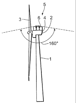
A wind power installation comprises a pylon and a machine
housing which is fitted on the pylon and which carries a rotor and a generator
connected thereto. The wind power installation is equipped with a
flight lighting arrangement which produces a light that is visible over a
long distance, wherein the flight lighting arrangement is provided with a
cover which substantially prevents the light from the flight lighting
arrangement
from being visible from the ground in the region of 0 to 2000 m
around the wind power installation. The invention eliminates the disadvantages
of prior art flight lighting arrangements for wind power installations
located within air traffic zones, as in the proximity of airports.


French Abstract

L'invention concerne une éolienne dont le type de construction est connu depuis longtemps. Ces éoliennes sont constituées généralement de plusieurs éléments tels qu'un pylône, sur lequel est monté un local des machines qui abrite le rotor de l'éolienne et le générateur associé pour produire l'énergie. Lorsque de telles installations d'éoliennes se trouvent dans des zones de circulation aérienne, donc dans des régions situées à proximité d'aéroports, elles doivent être équipées de dispositifs de signalisation déterminés pour que les véhicules de transport aérien soient prévenus à temps de l'existence de ces éoliennes constituant des constructions importantes. L'invention vise à éliminer les inconvénients que représentent jusqu'à présent les feux de balisage aériens. A cet effet, l'éolienne selon l'invention comporte un pylône, sur lequel est monté un local des machines qui abrite un rotor et un générateur associé, et elle est équipée d'un feu de balisage aérien qui produit une lumière visible de loin, de préférence une lumière clignotante. L'invention est caractérisée en ce que ce feu de balisage aérien est pourvu d'une couverture qui évite très largement que ladite lumière ne soit visible du sol dans un rayon de 0 à 2000 m, et de préférence de 0 à 700 m aux alentours de l'éolienne.

Claims

Note: Claims are shown in the official language in which they were submitted.


CLAIMS:

1. A wind power installation comprising:

a pylon and a machine housing arranged on the pylon,
wherein a rotor and a generator is arranged in the machine
housing,

a flight lighting arrangement for producing a light which is
visible over a long distance,

wherein the flight lighting arrangement comprises a cover
which prevents that the light from the flight lighting arrange-
ment is visible from ground in the region of 0 to 2000 m
around the wind power installation.


2. A wind power installation according to claim 1 characterised
in that the light of the flight lighting arrangement is not visible in a
region of about 0 to 1000 m beside the wind power installation and
at a height of about 3 to 10 m.


3. A wind power installation according to claim 1 or 2, wherein
the cover comprises a plate which is provided beneath or laterally of
the flight lighting arrangement.


4. A wind power installation according to any one of claims 1 to
3 characterised in that the cover is of a parabolic configuration,
wherein the flight lighting arrangement is disposed within the cover
and the cover permits the light of the flight lighting arrangement to
be visible at an angle of -10 to 90°, with respect to the horizontal.


5. A wind power installation according to any one of claims 1 to
4, wherein the cover is arranged such that the light from the flight
lighting arrangement is at most scarcely visible in a region laterally
of the wind power installation around the wind power installation at
a distance of 0 to 2000 m independent on the azimuth adjustment of
the machine housing of the wind power installation.


6

Description

Note: Descriptions are shown in the official language in which they were submitted.


= CA 02488542 2008-03-26

HAZARD NAVIGATION LIGHT FOR WIND TURBINES

The invention concerns a wind power installation. Such wind power
installations have long been known. They usually consist of a number of
components such as a pylon and a machine housing which is mounted
thereon and which accommodates the rotor of the wind power installation
and the generator connected thereto for producing energy. Whenever such
wind power installations are located within air traffic zones, that is to say
those regions which are directly in the relative proximity of airports, such
wind power installations must be provided with certain signalling devices so
that the attention of the air traffic is drawn to the existence of the wind
power installation as a large structure, in good time.
Signalling devices can also be coats of paint on the rotor blades (in
particular the tips thereof) of the wind power installation.
General guidelines for identifying obstacles to air travel are known
from 'Nachrichten fur Luftfahrer' ['News for Pilots'], Part I, NfL I 15/00,
27th January 2000.
The various flight lighting arrangements are also mentioned therein.
Another flight lighting arrangement is known from DE-U-200 08 289.
The object of the invention is to eliminate the previous
disadvantages of flight lighting arrangements.
The invention provides a wind power installation comprising a pylon
and a machine housing arranged on the pylon, wherein a rotor and a
generator is arranged in the machine housing, and a flight lighting
arrangement for producing a light which is visible over a long distance. The
flight lighting arrangement comprises a cover which prevents the light from
the flight lighting arrangement being visible from ground in the region of 0
to 2000 meters around the wind power installation.

1


CA 02488542 2008-03-26

1(a)
According to another embodiment, the light of the flight lighting
arrangement is not visible in a region of about 0 to 1000 meters beside the
wind power installation and at a height of about 3 to 10 meters.
According to another embodiment, the cover comprises a plate which
is provided beneath or laterally of the flight lighting arrangement.
According to another embodiment, the cover is of a parabolic
configuration, wherein the flight lighting arrangement is disposed within the
cover and the cover permits the light of the flight lighting arrangement to be
visible at an angle of -10 to 90 , with respect to the horizontal.
According to another embodiment, the cover is arranged such that the
light from the flight lighting arrangement is at most scarcely visible in a
region laterally of the wind power installation around the wind power
installation at a distance of 0 to 2000 meters independent on the azimuth
adjustment of the machine housing of the wind power installation.
In the wind power installation, provided below the flashing signalling
device is a cover which prevents the flashing device from being visible in a
given cone (viewed from the flight lighting arrangement) laterally of the wind
power installation as seen from the ground. The cone is preferably of a
width of at least 45 , but preferably 90 - 150 orthereabove to cover 180
(horizontal). Such a cover admittedly prevents a view on to the flight
lighting arrangement at an angle below the wind power installation, but


CA 02488542 2004-12-03

normal air traffic is still in a position to recognise the light of the flight
lighting arrangement.
If in addition the cover is a mirrored surface and in particular also is
of a parabolic configuration, that causes the flashing to appear in
strengthened form and more easily visible to the air traffic.
The device according to the invention provides that the flight lighting
arrangement is no longer experienced as being annoying even right in the
region of residences and light pollution for the residential population is
avoided.
Depending on the respective height of the flight lighting
arrangement, an angle of 1500 or more already means that, as viewed from
the ground, the light of the flight lighting arrangement is no longer to be
seen, at a distance of 0 to 2000 m, preferably only up to 1000 m. This
means that in particular the light of the flight lighting arrangement is no
longer experienced as being a burden in adjoining residential areas.
The invention is described in greater detail hereinafter by means of
an embodiment.
In the drawing:
Figure 1 shows a plan view of a wind power installation according to
the invention,
Figure 2 shows a side view of a wind power installation according to
the invention, and
Figures 3a, b, c, d and e show various embodiments of a wind power
installation according to the invention.
Figure 1 shows a plan view of a wind power installation 1 comprising
a pylon and a machine housing 2 mounted thereon as well as the rotor 3 of
the wind power installation and the machine housing casing (pod) 4. As can
be seen in Figure 2 provided on the pod is a flight lighting arrangement 5
which is caused to flash from time to time or constantly by a suitable
control (not shown). Provided below the flight lighting arrangement is a
cover 6 which prevents the light of the flight lighting arrangement from
being visible from the ground in a region laterally of the wind power
installation. That region can be 2000 m or more laterally of the wind power
2


CA 02488542 2004-12-03

installation (depending on the respective location), in which respect it is
usually sufficient if the range within which the light from the flight
lighting
arrangement is not to be seen is about 1000 m (from the ground) besides
the wind power installation.
The shape of the covered surface can be predetermined by a
corresponding shape of the cover or pod. If for example the cover
comprises a large circular disc, then the light of the flight lighting
arrangement is not visible in a conical region below the disc and, depending
on the respective diameter of the disc, the covered area is larger (increase
in the cone angle). If the flight lighting arrangement is in a parabolic cover
(Figure 3a) or box-shaped cover (3c), the angle covered can be up to 180
(with respect to the cone), that is to say in that case light from the flight
lighting arrangement is practically no longer visible below the horizontal,
with respect to the flight lighting arrangement. Such a large angle however
is usually scarcely necessary as the wind power installations in any case are
often located at relatively high, that is to say exposed positions, and the
buildings therearound are markedly below the height of the flight lighting
arrangement of the wind power installation.
If therefore the cover angle is about 160 to 170 (with respect to the
cone), then the light of the flight lighting arrangement is no longer visible
in a region of about 500 - 2000 m laterally of the wind power installation,
but at the same time the light from the flight lighting arrangement is
readily visible for all the flight traffic, as hitherto.
In principle it is also possible for the cover of the flight lighting
arrangement to be such that it is aiways only the same region in a given
lateral region of the wind power installation that is covered. If that cover
is
stationary or can be adjusted by motor means (upon rotation of the pod
about the point of rotation), therefore it is always only the same region
laterally of the wind power installation that is covered, independently of the
azimuth angle of the wind power installation. As Figures 3a - 3d show,
various variations in respect of the cover can be envisaged. In that respect
it is the position of the outer edge 7 of the cover 8 that is the determining
aspect for coverage.

3


CA 02488542 2004-12-03

The higher that outer edge is taken, the correspondingly greater is
the cover angie and the correspondingly greater also is the distance from
the wind power installation, within which the light from the flight lighting
arrangement is no longer visible.
As the disturbing influence of the light from the flight lighting
arrangement however decreases with the distance in relation to the wind
power installation, it would usually be sufficient if the cover provides a
'shadow range' which is 1500 to 3000 m or markedly less.

4

Representative Drawing
A single figure which represents the drawing illustrating the invention.
Administrative Status

For a clearer understanding of the status of the application/patent presented on this page, the site Disclaimer , as well as the definitions for Patent , Administrative Status , Maintenance Fee  and Payment History  should be consulted.

Administrative Status

Title Date
Forecasted Issue Date 2008-11-18
(86) PCT Filing Date 2003-06-04
(87) PCT Publication Date 2003-12-18
(85) National Entry 2004-12-03
Examination Requested 2004-12-03
(45) Issued 2008-11-18
Deemed Expired 2021-06-04

Abandonment History

There is no abandonment history.

Payment History

Fee Type Anniversary Year Due Date Amount Paid Paid Date
Request for Examination $800.00 2004-12-03
Application Fee $400.00 2004-12-03
Maintenance Fee - Application - New Act 2 2005-06-06 $100.00 2004-12-03
Maintenance Fee - Application - New Act 3 2006-06-05 $100.00 2006-04-18
Maintenance Fee - Application - New Act 4 2007-06-04 $100.00 2007-04-13
Maintenance Fee - Application - New Act 5 2008-06-04 $200.00 2008-04-30
Final Fee $300.00 2008-08-26
Maintenance Fee - Patent - New Act 6 2009-06-04 $200.00 2009-05-25
Maintenance Fee - Patent - New Act 7 2010-06-04 $200.00 2010-05-25
Maintenance Fee - Patent - New Act 8 2011-06-06 $200.00 2011-05-24
Maintenance Fee - Patent - New Act 9 2012-06-04 $200.00 2012-05-22
Maintenance Fee - Patent - New Act 10 2013-06-04 $250.00 2013-05-21
Maintenance Fee - Patent - New Act 11 2014-06-04 $250.00 2014-05-22
Maintenance Fee - Patent - New Act 12 2015-06-04 $250.00 2015-05-21
Maintenance Fee - Patent - New Act 13 2016-06-06 $250.00 2016-05-24
Maintenance Fee - Patent - New Act 14 2017-06-05 $250.00 2017-05-18
Maintenance Fee - Patent - New Act 15 2018-06-04 $450.00 2018-05-22
Maintenance Fee - Patent - New Act 16 2019-06-04 $450.00 2019-05-23
Maintenance Fee - Patent - New Act 17 2020-06-04 $450.00 2020-05-26
Owners on Record

Note: Records showing the ownership history in alphabetical order.

Current Owners on Record
WOBBEN, ALOYS
Past Owners on Record
None
Past Owners that do not appear in the "Owners on Record" listing will appear in other documentation within the application.
Documents

To view selected files, please enter reCAPTCHA code :


To view images, click a link in the Document Description column. To download the documents, select one or more checkboxes in the first column and then click the "Download Selected in PDF format (Zip Archive)" or the "Download Selected as Single PDF" button.

List of published and non-published patent-specific documents on the CPD .

If you have any difficulty accessing content, you can call the Client Service Centre at 1-866-997-1936 or send them an e-mail at CIPO Client Service Centre.


Document
Description 
Date
(yyyy-mm-dd) 
Number of pages   Size of Image (KB) 
Cover Page 2005-02-21 2 46
Drawings 2004-12-03 3 26
Claims 2004-12-03 1 40
Abstract 2004-12-03 1 34
Description 2004-12-03 4 163
Representative Drawing 2004-12-03 1 4
Abstract 2007-05-11 1 20
Claims 2007-05-11 2 45
Description 2008-03-26 5 192
Representative Drawing 2008-11-04 1 4
Cover Page 2008-11-04 2 39
PCT 2004-12-03 11 407
Assignment 2004-12-03 2 97
PCT 2004-12-03 4 181
Prosecution-Amendment 2006-11-14 2 47
Prosecution-Amendment 2007-05-11 5 110
Prosecution-Amendment 2007-09-28 2 56
Prosecution-Amendment 2008-03-26 4 145
Correspondence 2008-08-26 1 30