Note: Descriptions are shown in the official language in which they were submitted.
CA 02490967 1996-09-27
~.
-1-
COMPOSITE SPOOLABLE TUBE
Related Applications
This application is a divisional of Canadian Patent Application Serial No.
2,409,304, filed September 27, 1996, and which is a division of Canadian
Patent
Application Serial No. 2,321,536, filed September 27, 1996, and which is a
division of
Canadian Patent Application Serial No. 2,233,295, filed September 27, 1996.
Field of the Invention
The present invention relates generally to spoolable tubing suitable for
use in the oil industry, and more particularly to spoolable tubing consisting
of a
composite material with the ability to withstand high stress.
Backeround of the Invention
Spoolable tubing, that is tubing capable of being spooled upon a reel, is
commonly used in numerous oil well operations. Typical oil well operations
include
running wire line cable down hole with well tools, working over wells by
delivering
various chemicals down hole, and performing operations on the interior surface
of the
drill hole. The tubes used are required to be spoolable so that the tube can
be used in
conjunction with one well and then transported on a reel to another well
location. Steel
coiled tubing is typically capable of being spooled because the steel used in
the product
exhibits high ductility (i.e. the ability to plastically deform).
Unfortunately, the repeated
spooling and use of steel coiled tubing causes fatigue damage that can
suddenly cause
the steel coiled tubing to fracture and fail. The hazards of operating steel
coiled tubing,
i.e. risk to personnel and high economic cost resulting from down time needed
to retrieve
the broken tubing sections, forces steel coiled tubing to be retired after a
relatively few
number of trips into a well.
Steel coiled tubing has also proven to be subject to expansion after
repeated uses. Tube expansion results in reduced wall thickness with the
associated
reduction in the pressure carrying capability of the steel coiled tubing.
Steel coiled
tubing known in the art is typically limited to an internal pressure up to
about 5,000 psi
(34.455 x 10³ Pa). Accordingly, higher pressure and continuous flexing
typically
reduces the steel tube's integrity and service life.
CA 02490967 1996-09-27
-2-
For example, the present accepted industry standard for steel coiled tube
is an A-606 type 4 modified HSLA steel with yield strengths ranging from 70
ksi
(482.370 Pa) to 80 ksi (551,280 Pa). The HSLA steel tubing typically undergoes
bending, during the deployment and retrieval of the tubing, over radii
significantly less
than the minimum bending radii needed for the material to remain in an elastic
state.
The repeated bending of steel coiled tubing into and out of plastic
deformation induces
irreparable damage to the steel tube body leading to low-cycle fatigue
failure.
Additionally, when steel coiled tubing is exposed to high internal
pressures and bending loads, the isotropic steel is subjected to high triaxial
stresses
imposed by the added pressure and bending loads. The high triaxial stresses
result in
significant plastic deformation of the tube and diametral growth of the tube
body,
commonly referred to as "ballooning". When the steel coiled tube experiences
ballooning, the average wall thickness of the tube is reduced, and often
causes a bursting
of the steel tube in the area of decreased thickness.
Steel coiled tubes also experience thinning of the tube walls due to the
corrosive effects of materials used in the process of working over the well
and due to
materials located on the inner surface of the well bore. The thinning
resulting from
corrosive effects of various materials causes a decrease in the pressure and
the tensile
load rating of the steel coiled tubing.
It is, therefore, desirable to provide a non-steel coil tubing which is
capable of being deployed and spooled under borehole conditions, which does
not suffer
from the limitations of steel tubing and is highly resistant to chemicals.
For the most part, prior art non-metallic tubular structures that are
designed for being spooled and also for transporting fluids, are made as a
hose whether
or not they are called a hose. An example of such a hose is the Feucht
structure in U.S.
Patent 3,856,052 which has longitudinal reinforcement in the side walls to
permit a
flexible hose to collapse preferentially in one plane. However, the structure
is a classic
hose with vulcanized polyester cord plies which are not capable of carrying
compression
loads or high external pressure loads. Hoses typically use an elastomer such
as rubber to
hold fiber together but do not use a high modulus plastic binder such as
epoxy. Hoses
CA 02490967 1996-09-27
-3-
are designed to bend and carry internal pressure but are not nonmally
subjected to
external pressure or high axial compression or tension loads.
When the ends of a hose are subjected to opposing forces, the hose is said
to be under tension. The tensile stress at any particular cross-section of the
hose is
defined as the ratio of the force exerted on that section by opposing forces
to the cross-
sectional area of the hose. The stress is called a tensile stress, meaning
that each portion
pulls on the other.
With further reference to a hose subjected to opposing forces, the term
strain refers to the relative change in dimensions or shape of the hose that
is subjected to
stress. For instance, when a hose is subjected to opposing forces, a hose
whose natural
length is LO will elongate to a length Ll = LO + Delta L, where Delta L is the
change in
the length of the hose caused by opposing forces. The tensile strain of the
hose is then
defined as the ration of Delta L to LO, i.e. the ratio of the increase in
length to the natural
length.
The stress required to produce a given strain depends on the nature of the
material under stress. The ratio of stress to strain, or the stress per unit
strain, is called an
elastic modulus. The larger the elastic modulus, the greater the stress needed
for a given
strain.
For an elastomeric type material, such as used in hoses, the elongation at
break is so high (typically greater than 400 percent) and the stress-strain
response so
highly nonlinear; it is common practice to define a modulus corresponding to a
specified
elongation. The modulus for an elastomeric material corresponding to 200
percent
elongation typically ranges from 300 psi (2067 x 103 Pa) to 2000 psi (13.782 x
103 Pa).
In comparison, the modulus of elasticity for typical plastic matrix material
used in a
composite tube is from 100,000 psi (689.4 x 10⁶ Pa) to 500,000 psi (3445.5 x
106 Pa) or
greater, with representative strains to failure of from 2 percent to 10
percent. This large
difference in modulus and strain to failure between rubber and plastics and
thus between
hoses and composite tubes is what permits a hose to be easily collapsed to an
essentially
flat condition under relatively low external pressure. This large difference
also
eliminates the hose's capability to carry high axial tension or compression
loads while
CA 02490967 1996-09-27
-4-
the higher modulus characteristic of the plastic matrix material used in a
composite tube
is sufficiently stiff to transfer loads into the fibers and thus resist high
external pressure
and axial tension and compression without collapse.
The procedure to construct a composite tube to resist high external
pressure and compressive loads involves using complex composite mechanics
engineering principles to ensure that the tube has sufficient strength. It has
not been
previously considered feasible to build a truly composite tube capable of
being bent to a
relatively small diameter and be capable of carrying internal pressure and
high tension
and compression loads in combination with high external pressure requirements.
Specifically a hose will not sustain high compression and external pressure
loads.
Accordingly, it is one object of this invention to provide an apparatus and
method for providing a substantially non-ferrous spoolable tube that does not
suffer from
the structural limitations of steel tubing and that is capable of being
deployed and
spooled under bore hole conditions.
A further object of the invention is to provide a composite coiled tube
capable of working over wells and delivering various chemicals down hole
quickly and
inexpensively.
Another object of the invention includes providing a coiled tubing capable
of repeated spooling and bending without suffering fatigue sufficient to cause
fracturing
and failing of the coiled tube.
Other objects of the invention include providing a spoolable tube capable
of carrying corrosive fluids without causing corrosion in the spoolable tube,
providing a
coiled rube having less weight, and providing a coiled tube capable of
withstanding
higher internal pressure levels and higher external pressure levels without
loosing tube
integrity.
These and other objects will be apparent from the description that follows.
CA 02490967 1996-09-27
-5-
General Descrintion of the Invention
The invention attains the foregoing objects by providing a composite
coiled tube that offers the potential to exceed the performance limitations of
isotropic
metals currently used in forming coiled tubes, thereby increasing the service
life of the
coiled tube and extending the operational parameters of the coiled tube. The
composite
coiled tube of the invention overcomes the disadvantages in present steel coil
tubing by
providing among other things, a composite layer that exhibits unique
anistropic
characteristics capable of providing improved burst and collapse pressures as
well as
improved tensile strength compression load strength and load carrying
capability.
The composite coiled tube of the present invention comprises a composite
layer having fibers embedded in a matrix and an inner liner formed from
polymeric
materials. The fibers in the composite layer are oriented to resist internal
and external
pressure and provide low bending stiffness. The composite coiled tube offers
the
potential to exceed the performance limitations of isotropic metals, thereby
increasing
the service life of the tube and extending operational parameters. In
addition, the fibers,
the matrix, and the liner used in the composite coiled tube can make the tube
impervious
to corrosion and resistant to chemicals used in treatment of oil and gas wells
or in
flowlines.
The service life potential of the composite coiled tube constructed in
accordance with the invention is substantially longer than that of
conventional steel tube
when subjected to multiple plastic deformation bending cycles with high
internal
pressures. Composite coiled tube also provides the ability to extend the
vertical and
horizontal reach of existing concentric well services. In one operation, the
composite
coiled tube is deployed as a continuous string of small diameter tubing into a
well bore to
perform a specific well bore procedure. When the service is completed, the
small
diameter tubing is retrieved from the well bore and spooled onto a large reel
for
transport to and from work locations. Additional applications of coiled
composite tube
are for drilling wells, flowlines, as well as for servicing extended reach
applications such
as remedial work in wells or flowlines.
In particular, the invention provides for a composite coiled tube having an
inner liner formed of polymeric materials and a composite layer enclosing the
inner liner.
CA 02490967 1996-09-27
-6-
The composite layer contains three fibers oriented in a triaxial braid. A
triaxial braid
structure is formed of three or more fibers braided in a particular
orientation and
embedded in a plastic matrix. In a triaxial braid, a first structural fiber
helically or
axially extends along the longitudinal axis of the tube. A second braiding
fiber is
clockwise helically oriented relative to the first structural fiber or
relative to the
longitudinal axis of the tube. A third braiding fiber is counter-clockwise
helically
oriented relative to the first structural fiber or relative to the
longitudinal axis of the tube.
In addition, the first structural fiber is interwoven with either the second
or the third or
both braiding fibers. The composite coiled tube constructed with this triaxial
braid
structure exhibits unique anistropic characteristics having enhanced burst
pressure
characteristics, collapse pressure characteristics, increased bending
characteristics,
tensile loads, and compression loads.
The composite layer can be constructed with a matrix material having a
tensile modulus of at least 100,000 psi (698.4 x 10⁶ Pa), a maximum tensile
elongation of
at least 5% and a glass transition temperature of at least 180 Degrees
Fahrenheit (82.2
Degrees Celsius). Increased tube strength can also be obtained by fonming a
layer
having at least 80%, by fiber volume, of the fibers helically oriented
relative to the
longitudinal axis of the tube at an angle between 30 and 70 degrees.
In accordance with further aspects of the invention, the composite tube
includes a liner that serves as a pressure containment member to resist
leakage of internal
fluids from within the tubing. The inner liner is formed of co-extruded
composite
polymers. The polymers forming the liner can also include homo-polymers or co-
polymers. The polymeric material forming the liner are impermeable to fluids
(i.e.
gasses and liquids). The inner liner can also include materials that are
chemically
resistive to corrosives.
The liner can be constructed to have improved mechanical properties that
enhance the bending characteristics, the strength characteristics, and the
pressure
characteristics of the coiled composite tube. For example, the liner can have
a
mechanical elongation of at least 25%, and a melt temperature of at least 250
Degrees
Fahrenheit (121 Degrees Celsius). The liner can also enhance the pressure
characteristics of the composite tube by increasing the bonding strength
between the
CA 02490967 1996-09-27
...
-7-
inner liner and the composite layer. This can be achieved by placing grooves
on the
exterior surface of the liner, such that the grooves can hold matrix material
that binds the
composite layer to the exterior of the liner.
Another feature of the invention includes providing a liner capable of
dissipating static charge buildup. A liner having an additive of carbon black
can prevent
static charge buildup. By preventing static charge buildup, the liner is more
likely to
prevent the ignition of flammable fluid circulating within the tube.
In a preferred embodiment, the composite layer is formed of three or more
fibers interwoven in a triaxial braid and suspended in a matrix material. For
example,
the composite layer can comprise a helically extending first fiber, a second
fiber
clockwise extending and helically oriented, and a third fiber counter
clockwise extending
and helically oriented. The first, second and third fibers are oriented such
that the first
fiber is interwoven with either the second fiber or the third fiber or both.
The composite
layer can also include additional plies formed of fiber and matrix. The fibers
in the
additional plies can have fibers oriented in many ways, including but not
limited to,
triaxially braiding, biaxially braiding, interwoven and filament wound.
Additional aspects of the invention provide for a separate interface layer
interposed between the liner and the composite layer. This interface layer
allows the
composite coiled tube to withstand extreme pressures inside and outside the
tube without
causing degradation of the composite tube. The interface layer bonds the
composite
layer to the liner. In addition, the interface layer can serve as a transition
layer between
the composite layer and the liner. For example, the interface layer can have a
modulus of
elasticity between the axial modulus of elasticity of the liner and the axial
modulus of
elasticity of the composite layer, thereby providing a smooth transition in
the modulus of
elasticity between the liner and the composite layer.
Other aspects of the invention include a composite coiled tube having a
pressure barrier layer. The pressure barrier layer can be located external to
the
composite layer for preventing fluids (i.e. gases or liquids) from penetrating
into the
composite tube. The pressure barrier layer also prevents external pressure
from being
directly applied to the outer surface of the inner liner, thereby preventing
exterior
CA 02490967 1996-09-27
-8-
pressure from collapsing the inner liner. The pressure barrier layer can be
formed of an
impermeable material such as either polymeric film (including polyester),
thermoplastic,
thermoset film, elastomer or metallic film. The impermeable material can be
helically or
circumferentially wrapped around the composite layer. In addition, the
pressure barrier
layer can include a fused particle coating. Preferably, the pressure barrier
layer has a
minimal tensile elongation of 10% and an axial modulus of elasticity of less
than
750,000 psi, to aid in the enhanced bending and pressure characteristics of
the composite
coiled tube.
Further features of the invention provide for a composite tube having an
outer protective layer external to the composite layer. The outer protective
layer can
provide an outer protective surface and an outer wear resistant surface. The
outer
protective layer can also resist impacts and abrasion. In those aspects of the
invention
having both a pressure barrier layer and a outer protective layer, the
pressure barrier
layer is typically sandwiched between the composite layer and the outer
protective layer.
Additionally, energy conductors including electrical wiring or fiber optics
may be formed as an integral part of the spoolable composite tube. Energy
conductors
commonly have low strain capability and thus can be damaged easily by large
deformations such as those imposed by bending. These energy conductors are
thus
oriented in a helical direction relative to the longitudinal axis of the tube.
This
orientation minimizes the strain on the energy conductor when the tube bends.
In
another embodiment, energy conductors can be embedded in an axial or helical
orientation directly into the polymeric liner.
Various embodiments of the invention exist which include one or more
aspects and features of the invention described above. In one embodiment, the
spoolable
composite tube comprises an inner liner and an outer composite layer. In all
embodiments, the tube can be designed to include or exclude an interface layer
sandwiched between the inner liner and the composite layer. The interface
layer
increases the bonding strength between the liner and the composite layer.
Other
embodiments provide for a composite tube including a liner, a composite layer,
and a
pressure barrier. Further embodiments include a liner, a composite layer, a
pressure
barrier, and an external protective layer. While in an additional embodiment,
the
CA 02490967 1996-09-27
-9-
composite tube might include only a liner, a composite layer, and a pressure
barrier. The
invention also contemplates a spoolable tube having a liner, an inner
composite layer, a
pressure barrier, and an outer composite layer surrounding the pressure
barrier.
In one aspect, the present invention provides a spoolable composite tube,
said tube comprising: a substantially fluid impervious inner liner formed from
polymeric
or metallic material, and a first composite layer enclosing said liner and
formed of fiber
and matrix, said first composite layer having a first fiber extending
helically and having a
second clockwise extending fiber and having a third counter clockwise
extending fiber,
such that said first fiber is interwoven with at least one of said second
fiber and said third
fiber.
In another aspect, the present invention provides a spoolable composite
tube for spooling onto a reel and for unspooling for deployment, said tube
extending
along a longitudinal axis and comprising: a substantially fluid impervious
inner liner
formed form polymeric or metallic material, and a first composite layer
enclosing said
liner, said first composite layer being formed of a matrix having a modulus of
elasticity
greater than 100,000 psi (689.4 x 10⁶ Pa) and a first set of fibers having at
least 80
percent, by fiber volume, of the fibers helically oriented relative to the
longitudinal axis
at an angle between 30 degrees and 70 degrees, wherein the tensile strain of
said
composite tube, formed from said liner and said composite layer, at the point
of
maximum tensile strain is at least 0.25 percent when spooled on the reel and
wherein
said composite tube substantially maintains an open bore configuration.
In another aspect, the present invention provides a spoolable composite
tube for spooling onto a reel and for unspooling for deployment, said
composite tube
having a longitudinal axis and comprising: a tubular, substantially fluid
impervious inner
liner formed from polymeric or metallic material, a first composite layer
enclosing said
liner and formed of a helically oriented first set of fibers and of polymeric
matrix having
a modulus of elasticity greater than 100,000 psi (689.4 x 10⁶ Pa), an exterior
layer
external to and enclosing said first composite layer, said exterior layer
being either a
pressure barrier layer formed of an impermeable film or an outer protective
layer
providing wear resistance and having an outer surface with a coefficient of
friction less
than the coefficient of friction of said composite layer, and wherein said
liner and said
CA 02490967 2008-01-15
10- -
composite layer and said exterior layer constitute a composite tube having a
tensile strain
of at least 0.25 percent at the point of maximum tensile strain when spooled
on reel and
while maintaining an open bore configuration.
In another aspect, the present invention provides a spoolable composite
tube extending along a longitudinal axis, said tube comprising: a
substantially fluid
impervious liner, a composite layer enclosing said liner, said composite layer
being
formed of fibers helically oriented relative to the longitudinal axis and
embedded in a
matrix having a modulus of elasticity greater than 689.4 x 10⁶ Pa (100,000
psi), and an
energy conductor helically oriented relative to the longitudinal axis, said
energy
conductor being embedded in said spoolable composite tube.
In another aspect, the present invention provides a spoolable tube
comprising: an inner liner; a composite layer enclosing said liner and
comprising high
strength fibers; an outer protective layer enclosing said composite layer and
inner liner;
wherein said spoolable tube has an open bore configuration when spooled on a
reel.
In another aspect, the present invention provides a spoolable tube
comprising: an inner liner; an energy conductor; a composite layer comprising
high
strength fibers; and an outer protective layer.
In a further aspect, the present invention provides a spoolable tube
comprising: inner layers comprising a liner and high strength fibers helically
wound
about said liner; and a seamless outer protective layer holding said inner
layers together;
wherein said spoolable tube has an open bore configuration when spooled on
reel.
Preferably, said outer protective layer comprises fillers.
Brief Description of the Drawings
A more complete understanding of the invention may be obtained by
reference to the drawings in which:
FIGURE 1 is a side view, partially broken away, of a composite coiled
tube constructed according to the invention that includes a liner and a
composite layer;
CA 02490967 1996-09-27
-11-
FIGURE 2 is a side view of a flattened out composite layer, constructed
according to the invention, that has triaxially braided fiber components and
which is
suitable for constructing the composite layer of the composite tube shown in
FIGURE 1;
FIGURE 3 is a cross-sectional view of the composite coiled tube having
an inner liner surrounded by multiple composite layers;
FIGURE 4 is a side view, partially broken away, of a composite coiled
tube constructed according to the invention having a liner, an interface
layer, and a
composite layer;
FIGURE 5 is a side view, partially broken away, of a composite coiled
tube constructed according to the invention having a liner, an interface
layer, a composite
layer, and a pressure barrier;
FIGURE 6 is a side view, partially broken away, of a composite coiled
tube constructed according to the invention that includes a liner, an
interface layer, a
composite layer, a pressure barrier, and an outer protective layer;
FIGURE 7 is a side view, partially broken away, of a composite coiled
tube constructed according to the invention that includes a liner, a composite
layer, and a
pressure barrier;
FIGURE 8 is a side view, partially broken away, of a composite coiled
tube constructed according to the invention comprising a liner, an inner
composite layer,
a pressure barrier, and an outer composite layer;
FIGURE 9 is a side view, partially broken away, of a composite coiled
tube constructed according to the invention that includes an energy conductor;
and
FIGURE 10 illustrates the bending events that occur when running coiled
tubing in and out of a well bore.
CA 02490967 2008-01-15
-12-
Detailed Description of Illustrated Embodiments
Composite fibers (graphite, Kevlar;~fiberglass, boron, etc.) have numerous
assets including high strength, high stiffness, light-weight, etc., however,
the stress strain
response of composite fibers is linear to failure and therefore non ductile.
Composite
coiled tubing must therefore address the strain limitations in another manner,
i.e.. by
providing a construction to meet the requirements with a near elastic response
or with
large deformations of the matrix. Such a composite arrangement must have high
resistance to bending stresses and internal pressure and external pressure. It
must also
have high axial stiffness, high tensile and compressive strength and be
resistant to shear
stress. All of these properties are combined in the composite tubular member
of the
invention to provide a coiled tubing which can be bent to a radius compatible
with
winding onto a reasonable size spool.
P.K. Mallick in the text book entitled Fiber-Reinforced Composites,
Materials, manufacturing and Design, defines a composite in the following
manner:
"Fiber-reinforced composite materials consist of fibers of high strength and
modulus
embedded in or bonded to a matrix with distinct interfaces (boundary) between
them. In
general, fibers are the principal load-carrying member, while the surrounding
matrix
keeps them in the desired location and orientation, acts as a load transfer
medium
between them and protects them from environmental damages due to elevated
temperatures and humidity, for example". This definition defines composites as
used in
this invention with the fibers selected from a variety of available materials
including
carbon, aramid, and glass and the matrix or resin selected from a variety of
available
materials including thermoset resin such as epoxy and vinyl ester or
thermosplastic
resins such as polyetheretherketone (PEEK), polyetherketoneketone (PEKK),
nylon, etc.
Composite structures are capable of carrying a variety of loads in combination
or
independently, including tension, compression, pressure, bending, and torsion.
Webster's Ninth New Collegiate Dictionary defines hose as "a flexible
tube for conveying fluids". By comparison, a hose is distinctly different from
a
composite tube. Hose products such as umbilical lines used in subsea
application are
constructed of high strength fibers such as aramid, dacron, or nylon laid down
in a
geodesic pattern onto a substrate plastic liner tubular structure.
Alteraatively, a hose
may be constructed of high strength fibers with a lower modulus binder such as
rubber.
* Trade-mark
CA 02490967 1996-09-27
-13-
In either case, hose is designed to carry pressure loads and to exhibit good
bending
flexibility, but a hose has very limited ability to carry compressive, tension
and torsion
loads or external pressure.
The composite tube described in this invention cannot only carry high
internal pressure but can also carry high compressive, tension and torsion
loads,
independently or in combination. Such capability is essential if the tubing is
to be used
for applications such as coiled tubing in which the tubing is pushed into a
high pressure
reservoir and to overcome the friction to movement within the well bore,
especially for
highly deviated or horizontal wells. In addition, the tube is required to cany
its own
weight as it is suspended for 20,000 ft. (6.096 km) or more in a well bore and
to be able
to have high pulling capability to extract tools or to overcome being struck
from sand
and circulating solids which have collapsed around the tube. Such loads in the
case of
coiled tubing in deep wells can be in excess of 20k lbs (9071 kg). The tubing
must also
be capable of carrying high torsion loads. It was not considered feasible
until the
development represented in the current patent application, that one could
design and
build a composite tube capable of being bent to a relatively small diameter
such as
required for coiled tubing spooling and simultaneously be capable of carrying
internal
pressure and other loads.
In forming composite structures, several well known techniques may be
used such as pultrusion, fiber winding, braiding and molding. In pultrusion,
fibers are
drawn through a resin impregnating apparatus, then through dies to provide the
desired
shape. Alternatively, the resin may be injected directly within the die. Heat
forming and
curing structures are provided in conjunction with the dies. In fiber winding,
the various
layers forming the composite structure are each formed by winding or wrapping
fibers
and a polymer matrix around a mandrel or some other underlying structure that
provide a
desired shape. Successive composite layers can then be applied to underlying
composite
layers. A triaxial braiding structure can be manufactured using the fiber
winding
techniques disclosed in Quigley, U.S. Patent No. 5,188,872 and in Quigley,
U.S. Patent
No. RE 35,081.
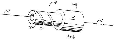
FIGURE 1 illustrates a composite coiled tube 10 constructed of an inner
liner 12 and a composite layer 14. The composite coiled tube is generally
formed as a
CA 02490967 1996-09-27
-14-
member elongated along axis 17. The coiled tube can have a variety of tubular
cross-
sectional shapes, including circular, oval, rectangular, square, polygonal and
the like.
The illustrated tube has a substantially circular cross-section.
Liner 12 serves as a pressure containment member to resist leakage of
internal fluids from within the composite coiled tube 10. In one embodiment
the liner 12
is metallic, and in an alternative embodiment the liner 12 is formed of
polymeric
materials having an axial modulus of elasticity exceeding 100,000 psi (6894 x
l O6Pa). A
liner having a modulus exceeding 100,000 psi (689.4 x 10⁶ Pa) is preferable as
it is
indicative of a tube capable of carrying high axial tension that does not
cause the tube to
compress or break. In addition, a liner with an axial modulus of elasticity
less than
500,000 psi (3445.5 x lO6Pa) advantageously allows the liner to bend, rather
than pull
away from the composite layer, as the composite tube is spooled or bent around
a reel.
The polymeric materials making up the liner 12 can be thermoplastic or
thermoset materials, for instance the liner can be formed of homo-polymers, co-
polymers, composite polymers, or co-extruded composite polymers. Homo-polymers
refer to materials formed from a single polymer, co-polymers refers to
materials formed
by blending two or more polymers and composite polymers refer to materials
formed of
two or more discrete polymer layers that have been permanently bonded or
fused. The
polymeric materials forming the inner liner are preferably selected from a
group of
various polymers, including but not limited to: polyvinylidene fluoride,
etylene
tetrafluoroethylene, cross-linked polyethylene ("PEX"), polyethylene, and
polyester.
Further exemplary thermosplastic polymers include materials such as
polyphenylene
sulfide, polyethersulfone, polyethylene terephthalate, polyamide,
polypropylene and
acetyl.
Liner 12 can also include fibers to increase the load carrying strength of
the liner and the overall load carrying strength of the spoolable composite
tube 10.
Exemplary composite fibers include graphite, kevlar, fiberglass, boron, and
polyester
fibers and aramid.
The liner 12 can be formed to be resistive to corrosive chemicals such as
heterocyclic amines, inorganic sulfur compound, and nitrogenous and acetylenic
organic
CA 02490967 1996-09-27
-15-
compounds. Three types of liner materials, polyvinylidene fluoride ("PVDF"),
etylene
tetrafluoroethylene ("ETFE"), and polyethylene ("PE"), have been found to meet
the
severe chemical exposure characteristics demanded in particular applications
involving
composite coiled tubing. Two particularly attractive materials for the liner
are the RC 10-
089 grade of PVDF, manufactured by Atochem, and Tefzel manufactured by
DuPont.
In other embodiments of liner 12, the liner comprises co-polymers formed
to achieve enhanced liner characteristics, such as corrosion resistance, wear
resistance
and electrical resistance. For instance, a liner 12 can be formed of a polymer
and an
additive such that the liner has a high electrical resistance or such that the
liner dissipates
static charge buildup within the composite tube 10. In particular, carbon
black can be
added to a polymeric material to form a liner 12 having a resistivity on the
order of 108
ohms/centimeter. Accordingly, the carbon black additive forms a liner 12
having an
increased electrical conductivity that provides a static discharge capability.
The static
discharge capability advantageously prevents the ignition of flammable fluids
being
circulated within the composite coiled tube 10.
In a further aspect of the invention, the liner 12 has a mechanical
elongation of at least 25%. A liner with a mechanical elongation of at least
25% can
withstand the increased bending and stretching strains placed upon the liner
as it is coiled
onto a reel and inserted into and removed from various well bores.
Accordingly, the
mechanical elongation characteristics of the liner prolong the overall life of
the
composite coiled tube 10. In addition, the liner 12 preferably has a melt
temperature of
at least 250 Fahrenheit so that the liner is not altered or changed during
the
manufacturing process for forming the composite coiled tubing. A liner having
these
characteristics typically has a radial thickness in the range of 0.02 inches
(0.0508 cm) -
0.25 inches (0.635 cm).
The composite layer 14 can be formed of a number of plies, each ply
having fibers disposed with a matrix, such as a polymer, resin, or
thennoplastic. The
fibers typically comprise structural fibers and flexible yarn components. The
structural
fibers are formed of carbon, nylon, polyester, aramid, thermoplastic, or
glass. The
flexible yarn components, or braiding fibers, are formed of nylon, polyester,
aramid,
thermoplastic or glass. The fibers included in layer 14 can be woven, braided,
knitted,
CA 02490967 1996-09-27
-16-
stitched, circumferentially wound or helically wound. In particular, the
fibers can be
biaxially or triaxially braided. The composite layer 14 can be formed through
pultrusion
processes, braiding processes, or continuous filament winding processes. A
tube formed
of the liner 12 and the composite layer 14 form a composite tube having a
maximum
tensile strain of at least 0.25 percent and being capable of maintaining an
open bore
configuration while being spooled on a reel.
The liner 12, illustrated in FIG. 1, can also include grooves 15 or channels
on the exterior surface of the liner. The grooves increase the bonding
strength between
the liner 12 and the composite layer 14 by supplying a roughened surface for
the fibers in
the composite layer 14 to latch onto. The grooves can further increase the
bonding
strength between the liner 12 and the composite layer 14 if the grooves are
filled with a
matrix. The matrix acts as a glue, causing the composite layer to be securely
adhered to
the underlying liner 12. Preferably, the grooves are helically oriented on the
liner
relative to the longitudinal axis 17.
FIGURE 2 shows a "flattened out" view of a preferred composite layer 14
having a fiber component 20 interwoven with a plurality of like or different
fiber
components, here shown as a clockwise helically oriented fiber component 16
and a
counterclockwise helically oriented fiber component 18. The configuration of
layer 14
shown in FIGURE 2, is appropriately denoted as a "triaxially braided" ply. The
fiber
components 16, 18, 20 are suspended in a matrix 22.
Helically oriented fibers are fibers that follow a spiral path. Typically,
helical fibers spiral around a mandrel underlying the composite tube or they
spiral
around underlying layers of the composite tube. For example, a helically
oriented fiber
follows a path comparable to the grooves around the shaft of a common screw. A
helical
fiber can be described as having an axial vector, an angle of orientation, and
a wrapping
direction. The axial vector indicates that the helical fiber can follow a path
along the
length of the tube 10 as it spirals around the tube, as opposed to a fiber
that continually
wraps around a particular section of the tube 10 without extending along the
length of the
tube. The angle of orientation of the helical fiber indicates the helical
fiber's angle
relative to a defined axis, such as the longitudinal axis 17. For example, a
helical fiber
having an angle of 0 degrees is a fiber that extends parallel to the
longitudinal axis and
CA 02490967 1996-09-27
-17-
that does not wrap around the tube 10, while a fiber having an angle of 90
degrees
circumferentially wraps around the tube 10 without extending along the length
of the
tube. The wrapping direction of the helical fiber is described as either
clockwise or
counter-clockwise wrapping around the tube 10.
The fiber components can be formed of carbon, glass, aramid, (such as
kevlar or twaron ), thermoplastic, nylon, or polyester. Preferably, fibers 16
and 18 act
as braiding fibers and are formed of either nylon, polyester, aramid,
thermoplastic or
glass. Fiber 20 acts as a structural fiber and is formed of either carbon,
glass, or aramid.
Fiber 20 increases the axial strength of the composite layer 14 and the
spoolable tube 10.
The matrix material 22 is generally a high elongation, high strength,
impact resistant polymeric material such as epoxy. Other alternative matrixes
include
nylon-6, vinyl ester, polyester, polyetherketone, polyphenylen sulfide,
polyethylene,
polypropylene, and thermoplastic urethanes.
Fiber 20 extends helically or substantially axially relative to the
longitudinal axis 17. The helically oriented fiber component 16 and 18 tend to
tightly
bind the longitudinal fiber component 20 with the matrix material 22 in
addition to
providing increased bending stiffness along axis 17 and increased tortional
strength
around axis 17. The helically oriented fiber components 16 and 18 can be
interwoven
amongst themselves. To this end, successive crossings of two fiber components
16 and
18 have successive "over" and "under" geometries.
According to a preferred aspect of the invention, the composite layer
includes a triaxial braid that comprises an axially extending fiber component
20, a
clockwise extending second fiber component 16 and a counter-clockwise
extending third
fiber component 18, wherein the fiber 20 is interwoven with either fiber 16 or
fiber 18.
Each helically oriented fiber 16, 18 can therefor be considered a braiding
fiber. In
certain aspects of the invention, a single braiding fiber, such as fiber 16
binds the fiber
component of a given ply together by interweaving the braiding fiber 16 with
itself and
with the axially extending fiber 20. A fiber is interwoven with itself, for
example, by
successively wrapping the fiber about the member and looping the fiber with
itself at
each wrap.
CA 02490967 1996-09-27
-18-
In another aspect of the invention, axially extending structural fiber 20 is
oriented relative to the longitudinal axis 17 at a first angle 28. Typically,
fiber 20 is
helically oriented at the first angle 28 relative to the longitudinal axis 17.
The first angle
28 can vary between 5 - 20 , relative to the axis. The first angle 28 can
also vary
between 30 - 70 , relative to the axis 17. Although it is preferred to have
fiber 20
oriented at an angle of 45 relative to axis 17.
The braiding fiber 16 is oriented relative to structural fiber 20 at a second
angle 24, and braiding fiber 18 is oriented relative to structural fiber 20 at
a third angle
26. The angle of braiding fibers 16 and 18, relative to structural fiber 20,
may be varied
between +\-10 and +\-60 . In one aspect of the invention, fibers 16 and 18
are oriented
at an angle of +\-20 relative to fiber 20.
One failure mechanism of the composite tube during loading, especially
under bending/pressure and tension and compression loading, is believed to be
the
development of micro-cracks in the resin and the introduction of microscopic
defects
between fibers. The development of some micro-cracks is also believed to be
inevitable
due to the severe loads placed on the tube during the manufacturing and
bending of the
tube. However, the effects of these micro-cracks and microscopic defects can
be
retarded by restraining the growth and accumulation of the micro-cracks and
microscopic
defects during the manufacturing and use of the composite coiled tube. The
applicants
have discovered that the selection of fibers 16 and 18 from the group of
fibers consisting
of nylon, polyester, glass and aramid mitigates and stops the growth of the
microscopic
defects. Thus, the selection of fibers 16 and 18 from the particularly noted
materials
improves the damage tolerance and fatigue life of the composite coiled tubing
10.
The applicant has further determined that the total volume of any
particular fibrous material in any selected layer of the composite coiled tube
affects the
overall mechanical characteristics of the composite coiled tube 10, including
a reduction
in crack propagation. It additionally follows that the total volume of any
particular
fibrous material in the whole composite coiled tube also affects the
mechanical
characteristics of the composite coiled tube 10. A composite coiled tube
having
improved strength and durability characteristics is obtained by forming a
composite layer
CA 02490967 1996-09-27
-19-
14 wherein the combined fiber volume of the clockwise extending and counter-
clockwise
extending braiding fibers 16 and 18 constitute less than 20% of the total
fiber volume in
the composite layer 14. Further, in accordance with this embodiment, the fiber
volume
of the axially extending fiber 20 should constitute at least 80% of the fiber
volume of the
composite layer 14. Preferably, the first composite layer 14 includes at least
80% by
fiber volume of substantially continuous fibers oriented relative to the
longitudinal axis
17 of the tube at an angle between 30-70 degrees.
When the matrix 20 is added to composite layer 14, the volume of matrix
in the layer 14 typically accounts for 35% or more of the volume in the
composite layer
14. Accordingly, the combined volume of all the fibers in composite layer 14
account
for less than 65% of the volume of the composite layer 14. It is thus evident,
that the
volume of fibers 16 and 18 account for less than 13% of the total volume of
the
composite layer 14 and that the volume of fiber 20 accounts for at least 52%
of the total
volume of the composite layer 14.
Matrix 20 in composite layer 14 is selected such that transverse shear
strains in the laminar can be accommodated without breaching the integrity of
the coil
composite tube 10. The strains generally is the result of bending the
spoolable composite
tube over the reel. These strains do not impose significant axial stresses on
the fiber, but
they do impose significant stresses on the matrix 20. Accordingly, matrix 20
should be
chosen such that the maximal tensile elongation is greater than or equal to
5%. The
applicant has further shown that choosing a matrix having a tensile modulus of
at least
100,000 psi (689.4 x 10⁶Pa) adds to the ability of the coil composite tube to
withstand
excessive strain due to bending. In accordance with the further aspect of the
invention,
the matrix 20 also has a glass transition temperature of at least 180
Fahrenheit (82.2C.)
so that the characteristics of the resin are not altered during high
temperature uses
involving the coiled composite tube 10. The tensile modulus rating and the
tensile
elongation ratings are generally measured as the coil composite tube is being
manufactured at 70 Fahrenheit (21.2C). Matrix materials having these
characteristics
include epoxy, vinyl ester, polyester, urethanes, phenolics, thermoplastics
such as nylon,
polypropelene, and PEEK.
CA 02490967 1996-09-27
-20-
FIGURE 3 illustrates a coiled composite tube 10 having an inner liner 12
and a first composite layer 14A, a second composite layer 14B, and a third
composite
layer 14C. Each of the composite layers if formed of fibers embedded in a
matrix, and
each of the composite layers successively encompasses and surrounds the
underlying
composite layer or liner 12. At least one of the composite layers, 14A, 14B,
14C,
includes a helically oriented fiber in a matrix. Preferably, at least one of
the composite
layers 14A, 14B, 14C, contains a ply as described in FIG. 2. In particular,
one of the
composite layers 14A, 14B, 14C, has a first helically extending fiber, a
second clockwise
extending fiber, and a third counterclockwise extending fiber wherein the
first fiber is
interwoven with at least one of the second and third fibers. The other two
composite
layers contain fiber suspended in a matrix. The fibers can be axially
extending,
circumferentially wrapped, or helically wrapped, biaxially braided or
triaxially braided.
According to one aspect of the invention, the fibers in each of the
composite layers are all selected from the same material. In other aspects of
the
invention, the fibers in each of the composite layers are all selected from
the different
materials. For example, composite layer 14A can comprise a triaxially braided
ply
having clockwise and counter-clockwise helically oriented fibers formed of
polyester and
having a helically extending fiber formed of glass; composite layer 14B can
comprise a
ply having a circumferentially wound kevlar fiber; and composite layer 14C can
comprise a triaxially braided ply having a clockwise and counter-clockwise
helically
oriented fibers formed of glass and having a helically extending fiber formed
of carbon.
The applicants have discovered that additional composite layers, beyond
the initial composite layer 14 of FIG. 1, enhance the capabilities of the
coiled composite
tube. In particular, the interaction between the additional composite layers
creates a
synergistic effect not found in a single composite layer. The applicant
discovered that
composite layers having carbon fibers carry proportionately more of the load
as the strain
in the coiled composite tube 10 increases, as compared to an equivalent design
using
glass fibers or aramid fibers. While a composite layer using kevlar (i.e.
aramid) fibers
provide excellent pressure/cyclical bending capabilities to the coiled
composite tube 10.
The kevlar fibers appear to have a weakness when compared to the carbon fibers
in
compressive strength. Accordingly, a coiled composite tube 10 incorporating
both
kevlar and carbon fibers provides a composite structure having improved
characteristics
CA 02490967 1996-09-27
-21-
not found in composite structures having composite layers formed of only
carbon fibers
or only kevlar fibers.
Accordingly, one aspect of the invention incorporates a composite layer
14A formed of carbon fibers and polyester fibers in a triaxially braided
structure and a
second composite layer 14B formed of kevlar fibers. The kevlar fibers can be
incorporated into either a conventional bi-axial braid, triaxial braid, or
helical braid. For
instance, the second composite layer can include two sets of aramid fibers bi-
axially
braided together. The coiled composite tube 10 having an inner composite layer
14A
formed with carbon fibers and an exterior composite layer 14B formed with
kevlar fibers
provides a coiled composite tube having balanced strength in two directions
and provides
a coiled composite tube having a constricting force which helps restrain the
local
buckling of delaminated sublamina and subsequent delamination growth, thereby
improving the fatigue resistance of the coiled composite tube 10. Certainly,
this aspect
of the invention can include a third composite layer 14C external to the
second
composite layer 14B. The third composite layer 14C can, for instance, include
a matrix
and a fiber helically oriented relative to the longitudinal axis 17.
In another aspect of the invention, as illustrated in FIGURE 3, the
composite layer 14A comprises a triaxially braided ply having an axially
extending fiber
formed of carbon and having a clockwise extending fiber and a counter-
clockwise
extending fiber both formed of polyester. In addition, the helically extending
fiber 20 is
oriented at an 45 angle to the axis of the coiled composite tube 10. Further
in
accordance with this embodiment, composite layer 14B is triaxially braided and
comprises a helically extending fiber formed of carbon and oriented at an
angle of 45
relative to the axis 17 of coiled composite tube 10. Composite layer 14B
further includes
a clockwise extending second fiber and a counter-clockwise extending third
fiber formed
of polyester. The third composite layer 14C, is biaxially braided, and
comprises a kevlar
fiber extending helically and oriented at a 54 angle to the axis 17 of the
composite
coiled tube 10.
FIGURE 4 illustrates a composite coiled tube elongated along an axis 17
and having an inner liner 12, an interface layer 56, and a composite layer 14.
The
interface layer 56 surrounds the liner 12 and is sandwiched between the liner
12 and the
CA 02490967 1996-09-27
r=
-22-
composite layer 14. The interface layer 56 improves the bonding between the
inner liner
12 and the composite layer 14.
It is important in the composite coiled tubing 10 that the liner 12 be
integrally attached to the composite layer 14. The necessity for a bonded
liner is that in
certain operating conditions experienced in down hole service, the external
surface of the
tube will be subjected to higher pressure than the interior of the tube. If
the liner is not
bonded to the composite layer 14 this external pressure could force the liner
to buckle
and separate from the composite layer such that the liner collapses. In
addition, loading
and bending of the tube may introduce microscopic cracks in the composite
layer 14
which could serve as microscopic conduits for the introduction of external
pressure to be
applied directly to the outer surface of the liner 12. Once again, these
external pressures
could cause the liner 12 to collapse. The interface layer 56 provides a
mechanism for
bonding the liner 12 to the composite layer 14 such that the liner does not
collapse under
high external pressures. The interface layer 56 can also reduce cracking and
the
propagation of cracking along the composite layer 14 and liner 12.
In accordance with one aspect of the invention, the interface layer 56
comprises a fiber reinforced matrix where the fiber volume is less than 40% of
the total
volume of the interface layer 56. The matrix and the forming interface layer
56
predominately act as an adhesive layer that bonds the liner 12 to the
composite layer 14.
The fibers within the interface layer 56 can be oriented in various ways,
including a
woven or non-woven structure. Preferably, the fibers within the interface
layer 56 are
polyester fibers. An interface layer having this structure is able to prevent
the liner from
separating from the composite layer even when the differential pressure
between the
exterior and interior of the tube 10 exceeds 1,000 psi (6894 x 103 Pa).
The matrix within the interface layer 56 can comprise a filled polymeric
layer or an unfilled polymeric layer. A filled polymeric layer uses a
polymeric matrix
having additives that modify the properties of the polymeric layer. The
additives used in
the filled polymeric layer include particulates and fibers. For instance,
carbon black
powder can be added to the polymeric layer to increase the conductivity of the
interface
layer 56, or chopped glass fibers can be added to the polymeric layer to
increase the
stiffness of the interface layer 56.
CA 02490967 1996-09-27
- 23 -
According to a further embodiment of the invention, the interface layer
has an axial modulus of elasticity that lies between the modulus of the
elasticity of the
liner 12 and the modulus of elasticity of the composite layer 14. The
interface layer 56
thus has a modulus of elasticity that transitions between the modulus of
elasticity of the
liner 12 and the composite layer 14. By providing a transitional modulus of
elasticity,
the interface layer aids in preventing the liner 12 from pulling away from the
composite
layer 14 during the bending action of the coiled composite tube 10.
The interface layer 56 furthermore increases the fatigue life of the coiled
composite tube 10. The structure of the interface layer 56 achieves this by
dissipating
shear stress applied along the length of the coiled composite tube 10. By
dissipating the
shear, the interface layer reduces the cracking and propagation of cracks
along the
composite layer 14.
FIGURE 5 illustrates a composite coiled tube elongated along an axis 17
and having an inner liner 12, an interface layer 56, a composite layer 14, and
a pressure
barrier layer 58. The pressure barrier layer 58 prevents gases or liquids
(i.e. fluids) from
penetrating into the composite coiled tube 10.
It is important for two reasons that fluids not penetrate into the composite
layer 14. First, a fluid that penetrates through the tube 10 to liner 12 can
build up to a
sufficient level of pressure capable of collapsing the liner 12. Second, a
fluid that
penetrates the coiled composite tube 10 during exposure in the well bore 36
may outgas
when the coil composite tube 10 is returned to atmospheric pressure.
Accordingly, a coiled composite tube 10 can function effectively without
a pressure barrier layer 58 under certain conditions. For example, when micro-
fractures
and defects in the composite layer 14 do not develop to a size that allows
fluids to
penetrate the composite layer 14, a pressure barrier layer is not necessary.
However,
when micro-fractures and passages through the composite layer 14 do not allow
for the
migration of fluids the use of a pressure barrier layer 58 is preferred. As
illustrated in
FIG. 5, the pressure barrier layer 58 generally is positioned outside of the
composite
layer 14.
CA 02490967 1996-09-27
-24-
The pressure barrier layer 58 can be formed of a metal, themoplastic,
thermoset films, or an elastomer such as a rubber sheet. All these various
materials can
function as a pressure barrier because they substantially prevent the
diffusion of fluids.
Preferably properties of the pressure barrier layer include low permeability
to fluids (i.e.
gases or liquids), high elongation, and bondability to composite layer 14. It
is also
preferred that the pressure barrier layer 58 have a maximum tensile elongation
of 10%
and an axial modulus of elasticity of less than 750,000 psi (5168250 X 103Pa).
These
values of tensile elongation and modulus of elasticity are measured at 70
Fahrenheit
during the manufacturing of the coiled composite tube 10. The permeability of
the
pressure barrier layer should be less than 0.4 x 10 to the -10 ccs per sec-cmz-
cm cmhg.
The impermeable pressure barrier layer 58 can be formed of an
impermeable films formed of metals or polymers. For instance, acceptable
polymeric
films include films formed of polyester, polyimide, polyamide, polyvinyl
fluoride,
polyvinylidene fluoride, polyethylene and polypropylene, or other
thermoplastics.
The impermeable film of layer 58 can be a seamless polymer layer which
is co-extruded or formed via a powder deposition process. Alternatively, the
impermeable film can be helically wrapped or circumferentially wrapped around
the
composite layer to form an overlapping and complete barrier. That is, the
fiber or
material forming the pressure barrier layer must be wrapped in such a fashion
that no
gaps exist and the pressure barrier layer 58 is sealed.
Another aspect of the invention provides for a pressure barrier layer 58
having a fused particle coating. A fused particle coating is formed by
grinding a
polymeric material into a very fine powder. The fine powder is then heat-fused
onto the
other materials forming the pressure barrier layer 58 or onto the underlying
composite
layer 14.
FIGURE 6 illustrates a composite coiled tube elongated along an axis 17
and having an inner liner 12, an interface layer 56, a composite layer 14, a
pressure
barrier layer 58 and an outer protective layer 60. The interface layer 56
enhances the
bond between the composite layer 14 to the inner liner 12. The pressure
barrier layer 58
CA 02490967 1996-09-27
-25-
prevents fluids from penetrating into the composite coiled tube 10. The outer
protective
layer 60 provides wear resistance, impact resistance, and an interface layer
for the
coupling for the coiled composite tube 10. The protective layer is positioned
such that it
surrounds the pressure barrier 58.
Outer protective layer 60 provides abrasion resistance and wear resistance
by forming an outer surface to the coil composite tube that has a low co-
efficient of
friction thereby causing objects to slip off the coiled composite tube. In
addition, the
outer protective layer 60 provides a seamless layer for holding the inner
layers of the
coiled composite tube together. The outer protective layer can be formed of a
filled or
unfilled polymeric layer. Alternatively, the outer protective layer 60 can be
formed of a
fiber, such as kevlar or glass, and a matrix. The fibers of the outer
protective layer 60
can be woven in a mesh or weave pattern around the inner layers of the coiled
composite
tube 10, or the fibers can be braided or helically braided around the inner
layers of tube
10. In either case, the fibers in the outer protective layer are wrapped
helically around
the inner layers of the coiled composite tube 10 in order to provide a
seamless structure.
It has further been discovered by the applicant that particles can be added
to the outer protective layer to increase the wear resistance of the outer
protective layer
60. The particles used can include any of the following, individually or in
combination
with one another: ceramics, metallics, polymerics, silicas, or fluorinated
polymers.
Adding Teflon (MP 1300) particles and an aramid powder (PD-T polymer) to the
matrix of the outer protective layer 60 has been found to be one effective way
to reduce
friction and enhance wear resistance.
In the case where the outer protective layer includes fibers, the particles
added to the outer protective layer 60 are such that they consist of less than
20% by
volume of the matrix. In the case where the outer protective layer does not
contain fiber,
a particulate such as Teflon MP 1300 can also be added to the polymeric
protective
layer. When the outer layer 60 does not include fiber, the particles typically
comprise
less than 60% by coating volume of the outer wear resistant layer 60.
FIGURE 7 illustrates an embodiment of the composite coiled tube
elongated along an axis 17 and having a liner 12, a composite layer 14, and a
pressure
CA 02490967 1996-09-27
-26-
barrier 58. FIG. 7 is similar to FIG. 5, except that it lacks the interface
layer 56.
Particularly, the inner liner 12 is positioned internally to the composite
layer 14, and the
composite layer 14 is positioned internally to the pressure barrier 58. This
figure
illustrates, among other things, that the interface layer 56 can either be
included or
removed from all embodiments of the invention, depending upon whether the
circumstances require the use of an interface layer to increase the bonding
strength
between the liner and the composite layer.
FIGURE 8 illustrates another embodiment of a composite coiled tube
elongated along an axis 17, the composite tube includes a liner 12, a first
composite layer
14, a pressure barrier 58, and a second composite layer 14'. In this
embodiment, the first
composite layer 14 surrounds the internal liner, and the pressure barrier
surrounds the
first composite layer 14. In addition, the second composite layer 14'
surrounds the
pressure barrier 58. Particularly, the pressure barrier is sandwiched between
two
composite layers 14 and 14'.
Composite layer 14' can be structured in any manner that composite layer
14 can be structured, but the layers 14 and 14' need not be identical. In
addition, either
composite layer 14 or composite layer 14' can include multiple composite
layers as
illustrated in FIG. 3. The external composite layer 14' proves useful in
providing an
exterior surface capable of engaging a coupling device.
The external composite layer 14' can also be fashioned to act as an outer
protective layer capable of providing abrasion resistance and wear resistance.
This can
be achieved by forming the external composite layer 14' from a filled or
unfilled
polymeric layer. The layer 14' can also achieve increased abrasion and wear
resistance
by helically wrapping or braiding those fibers forming composite layer 14'
around the
inner layers of the tube 10. Furthermore, the external composite layer 14' can
be
fashioned to reduce the friction of the exterior of tube 10 by adding
particles to the
external composite layer 14'. The particles can include ceramics, metallics,
polymerics,
silicas, or fluorinated polymers.
FIGURE 9 illustrates a composite coiled tube elongated along an axis 17
wherein the composite tube includes a liner 12, a composite layer 14, and an
energy
CA 02490967 2008-01-15
-27-
conductor 160 forming part of the composite layer 14. The energy conductor
provides a path
for passing power, communication or control signals from the surface down
through the tube to
a machine attached to the end of the tube.
The energy conductor 160 can be located in either the liner, the composite
layers, or the pressure barrier forming the tube 10. But it is preferable to
locate the energy
conductors in those layers nearest the interior surface of the tube and not in
those layers
located near the exterior surface of the tube. If an energy conductor is
located near the exterior
surface of the tube it is more likely to be subjected to corrosive surfacesor
materials located
outside the tube 10. In addition, an energy conductor located near the
interior of the tube 10
will be subjected to smaller bending strains when compared to an energy
conductor located
near the exterior of the tube.
An energy conductor can be embedded in any of the layers forming the tube 10
using the same methods known in the art for adding a fiber to the composite
layer. Typically,
an energy conductor is wound onto a mandrel or any underlying structure while
applying a
matrix. Energy conductors can also be added to a fiber composite layer with a
pultrusion
process. For example, the energy conductor can be drawn through a resin
impregnating
apparatus, then through dies to provide the desired shape. Alternatively, the
conductor can be
embedded in the polymer liner.
The energy conductor 160 may be an electrical or optical conductor of any
material or substance capable of being modulated with information data or
electrical power. A
primary concern in placing the conductor 160 in the inner areas of the
composite tube 10 is to
ensure that the bending strains on the conductor 160 are minimized. This is
particularly
critical if the conductor 160 is a fiber optic cable. Moreover, the energy
conductor 160 is
typically helically oriented relative to the longitudinal axis 17 of the
composite tube to
minimize the bending strain on conductor 160. The helical orientation allows
the compression
strain experienced by the section of the conductor located on the interior
bend of the tube to be
offset by the expansion strain experienced by the section of the conductor
located on the
exterior bend of the tube. That is, the conductor 160 is able to substantially
distribute the
opposing strains resulting from the bending action of the composite tube
across the length of
the conductor 160, thereby preventing irreparable damage to the conductor.
CA 02490967 1996-09-27
-28-
FIGURE 10 illustrates the bending cycles that a coiled composite tube 10
is subjected to when performing a typical coiled tubing service. The tubing 10
is
inserted and removed from a well bore 36 located below the ground surface. A
reel 42 is
provided on the surface and the composite coiled tube 10 is stored on the reel
42. An
injector assembly 38 is located on the surface over the well bore 36. Injector
assembly
38 typically contains a roller belt 40 used to guide the coiled composite tube
10 through
the injector assembly 38 into the well bore 36. The coiled composite tube 10
typically is
subjected to six bending events as it is inserted and removed from the well
bore 36. The
first bending event 44 takes place when the coiled composite tube 10 is pulled
off the
service reel 42. When the coiled composite tube 10 reaches the assembly 38,
the coiled
tube passes through two bending events 46 and 48. The bending events 50, 52
and 54
are the reverse of bending events 44, 46, 48 and occur as the coiled composite
tube 10 is
extracted from the well bore 36. The insertion and extraction of the tube 10
thus results
in a total of six bending events for every round trip of the coiled composite
tube 10. The
current steel tubing being used in the field can generally be cycled three
time through the
bending events described in FIGURE 4 in conjunction with high internal
pressures
before the steel tubing fails. In comparison, the coiled composite tube of the
applicant's
invention can be cycled 10,000 times through the bending events described in
FIGURE
4.
It is also to be understood that the following claims are to cover all
generic and specific features of the invention described herein, and all
statements of the
scope of the invention which, as a matter of language, might be said to fall
there
between.
Having described the invention, what is claimed as new and secured by
Letters Patent is: