Note: Descriptions are shown in the official language in which they were submitted.
CA 02494148 2005-O1-31
WO 2004/015708 PCT/KR2003/001610
DISC WITH TEMPORARY DISC DEFINITION STRUCTURE (TDDS)
AND TEMPORARY DEFECT LIST (TDFL), AND METHOD OF AND
APPARATUS FOR MANAGING DEFECT IN THE SAME
s Technical Field
The present invention relates to disc defect management, and
more particularly, to a disc in which a temporary defect management
information area and a temporary management area are formed, and a
method and apparatus for managing a defect in such a disc.
io
Background Art
Defect management is performed to allow a user to rewrite user
data of a portion of a user data area in which a defect occurs in a new
portion of the user data area of a disc, thereby compensating for a loss
is in data caused by the defect. In general, defect management is
performed using linear replacement or slipping replacement methods.
In the linear replacement method, a user data area in which a defect
occurs is replaced with a spare data area having no defects. In fhe
slipping replacement method, a user data area having a defect is slipped
2o to use the next user data area having no defects.
Both linear replacement and slipping replacement methods are
applicable only to discs such as a DVD-RAM/RW on which data can be
repeatedly recorded and recording can be performed using a random
access method. In other words, the conventional linear replacement and
2s slipping replacement methods cannot be applied to write-once discs on
which recording is allowed only once. In general, the presence of
defects in a disc is checked by recording data on the disc and confirming
whether the data can be recorded on the disc. However, once the data
is recorded on a write-once disc, it is impossible to overwrite new data
3o and manage defects therein.
CA 02494148 2005-O1-31
WO 2004/015708 PCT/KR2003/001610
Meanwhile, after the development of CD-R and DVD-R, a
high-density write-once disc having a recording capacity of several dozen
of GB has been introduced. This type of disc can be used as a backup
disc since it is not expensive and allows random access, which enables
s~ fast reading operations. However, defect management is not available
for write-once discs. Therefore, a backup operation is discontinued
when a defective area (i.e., an area where a defect occurs) is detected
during the backup operation because defect management on a
write-once disc cannot be performed.
io In general, the backup operation is performed when a system is
not frequently used. Thus, backup operations are often performed at
night when a system manager does not operate the system. In this
case, it is more likely that the backup operation will be stopped because
a defective area of a write-once disc is detected and the backup
is operation for the system will therefore not be performed in a reliable
manner.
Disclosure of the Invention
The present invention provides a write-once disc with a data
2o structure which allows defect management, and a method of and
apparatus for managing a defect in such a disc.
The present invention also provides a write-once disc with a data
structure which allows defect management even if a defect occurs on the
disc during recording operations, thereby rendering successful recording
2s operations, and a method of and apparatus for managing a defect in a
disc having the defect management.
Additional aspects and advantages of the invention will be set
forth in part in the description which follows and, in part, will be obvious
from the description, or may be learned by practice of the invention.
2
CA 02494148 2005-O1-31
WO 2004/015708 PCT/KR2003/001610
According to an aspect of the present invention, a disc includes a
defect management area in at least one of a lead-in area, a lead-out
area, and an outer area; a temporary defect information area in a data
area and in which temporary defect information is recorded; and a
temporary defect management information area in at least one of the
lead-in area, and the lead-out area.
According to another aspect of the present invention, a method of
managing a defect in a disc includes recording defect information
regarding data recorded in a recording operation, and defect information
io regarding data recorded in a previous recording operation as first
temporary defect information in a data area of the disc; and recording the
first temporary defect information and defect information regarding data
recorded in a next recording operation as second temporary defect
information in the data area.
is According to yet another aspect of the present invention, a
method of managing a defect in a disc includes recording defect
information regarding data recorded in a data area of the disc according
to a first recording operation, defect information regarding data recorded
in the data area according to a second recording operation, defect
2o information regarding data recorded in the data area according to an
n-1St recording operation, and defect information regarding data recorded
in the data area according to an nt" recording operation, as nt" temporary
defect information in the data area; and recording defect management
information for managing the nt" temporary defect information as nt"
2s temporary defect management information in a temporary defect
management information area, where n is an integer.
It is preferable, but not required, that the method further includes
recording a last recorded temporary defect information and temporary
defect management information in a defect management area during
3o finalization of the disc.
3
CA 02494148 2005-O1-31
WO 2004/015708 PCT/KR2003/001610
It is preferable, but not required, that the recording nt" temporary
defect information includes recording the data in a predetermined unit;
verifying the recorded data to detect an area of the disc in which a defect
exists; storing in a memory information for designating an area covering
the area having the defect and data recorded after the area having the
defect as a defective area; recording the data in a predetermined unit
after the defective area; repeating verifying and storing at least once; and
reading the information from the memory and recording the read
information in an nt" temporary defect information area of the data area
io when an nt" recording operation is to end.
It is more preferable, but not required that the recording the nt"
temporary defect information further includes recording information for
designating the n~" temporary defect information area as a defective area
in the nt" temporary defect information area.
is According to still another aspect of the present invention, a
recording apparatus includes a recording unit that records data in a data
area of a disc according to a recording operation; and a controller that
controls the recording unit to record defect information regarding data,
which is recorded in a data area according to a recording operation, as
2o temporary defect information in the data area and record temporary
defect management information for managing the temporary defect
information in a temporary defect management information area in at
least one of a lead-in area and a lead-out area of the disc.
According to still another aspect of the present invention, a
zs recording apparatus includes a recording unit that records data on a disc;
and a controller that controls the recording unit to record defect
information regarding data recorded in a data area of the disc according
to a first recording operation through an nt" recording operation as nt"
temporary defect information in the data area; and controls the recording
3o unit to record defect management information for managing the ntn
4
CA 02494148 2005-O1-31
WO 2004/015708 PCT/KR2003/001610
temporary defect information as nth temporary defect management
information in a temporary defect management information area where n
is an integer.
According to still another aspect of the present invention, a disc
s includes a defect management area in at least one of a lead-in area and
a lead-out area; a temporary defect information area that is in a data
area and in which temporary defect information is recorded; a temporary
defect management information area that is in at least one of the lead-in
area and the lead-out area and in which temporary defect management
to information for managing the temporary defect information is recorded;
and a defect management area that is formed in at least one of the
lead-in area and the lead-out area and in which are recorded temporary
defect information last recorded in the temporary defect information area
and temporary defect management information last recorded in the
is temporary defect management information area.
According to still another aspect of the present invention, a disc
includes a defect management area in at least one of a lead-in area, a
lead-out area, and an outer area; a temporary defect information area
that is in a data area and in which temporary defect information is
2o recorded; a temporary defect management information area that is in the
lead-in area, the lead-out area, and an outer area and in which is
recorded temporary defect management information; and a defect
management area that is in the lead-in area, the lead-out area, and the
outer area and in which temporary defect information last recorded in the
2s temporary defect information area and temporary defect management ~~.
information last recorded in the temporary defect management
information area are recorded.
According to still another aspect of the present invention, a
method of managing a defect in a disc includes recording defect
3o information regarding data recorded in a data area for every recording
CA 02494148 2005-O1-31
WO 2004/015708 PCT/KR2003/001610
operation as temporary defect information in the data area; recording
defect management information for managing the temporary defect
information as temporary defect management information in a temporary
defect management information area in at least one of a lead-in area and
a lead-out area; and recording the temporary defect information and the
temporary defect management information in a defect management area
formed ~in at least one of the lead-in area and the lead-out area, during
finalization of the disc.
According to still another aspect of the present invention, a
io method of managing a defect in a disc includes recording as nt"
temporary defect information in the data area defect information
regarding data recorded in a data area of the disc according to a first
recording operation, defect information regarding data recorded in the
data area according to a second recording operation, defect information
is regarding data recorded in the data area according to an n-1St recording
operation, and defect information regarding data recorded in the data
area according to an nt" recording operation; recording defect
management information for managing the nt" temporary defect
information as nt" temporary defect management information in a
2o temporary defect management information area, where n is an integer,
and recording a last recorded temporary defect information and
temporary defect management information in a defect management area
during finalization of the disc.
According to still another aspect of the present invention, a
2s recording apparatus includes a recording unit that records data in a data
area of a disc according to a recording operation; and a controller that
controls the recording unit to record defect information regarding the
recorded data as temporary defect information in the data area; controls
the recording unit to record defect management information for
3o managing the temporary defect information as temporary defect
6
CA 02494148 2005-O1-31
WO 2004/015708 PCT/KR2003/001610
management information in a temporary defect management information
area that is in at least one of a lead-in area and a lead-out area of the
disc; and controls the recording unit to record the temporary defect
information and temporary defect management information in a defect
management area that is formed in at least one of the lead-in area and
the lead-out area.
According to still another aspect of the present invention, a
recording apparatus includes a recording unit that records data in a data
area of a disc according to first through nt" recording operations; and a
io controller that controls the recording unit to record defect information
regarding the dafia recorded according to the first recording through nt"
recording operations as nt" temporary defect information in the data area;
controls the recording unit to record defect management information for
managing the nt" temporary defect information as nt" temporary defect
is management information in a temporary defect management information
area; and controls the recording unit to record a last recorded temporary
defect information and temporary defect management information in a
defect management area, where n is an integer.
According to still another aspect of the present invention, a disc
2o includes a defect management area in at least one of a lead-in area and
a lead-out area; a temporary defect information area that is in a data
area and in which temporary defect information is recorded; and a
temporary defect management information area that is formed in at least
one of the lead-in area and the lead-out area and in which temporary
2s defect management information for managing the temporary defect
information is recorded, and wherein the temporary defect information
and the temporary defect management information are recorded again
when a disc defect is detected using a verify-after-write method.
According to still another aspect of the present invention, a disc
3o includes a defect management area in at least one of a lead-in area and
7
CA 02494148 2005-O1-31
WO 2004/015708 PCT/KR2003/001610
a lead-out area; a temporary defect information area that is in a data
area and in which is recorded temporary defect information; and a
temporary defect management information area that is in at least one of
the lead-in area, the lead-out area, and the outer area and in which is
s recorded temporary defect management information is recorded, where
the last recorded temporary defect information that was last recorded in
the temporary defect information area and the last recorded temporary
defect management information that was last recorded in the temporary
defect management information area are recorded in the defect
to management area during finalization of the disc, and the temporary
defect information and the temporary defect management information
are recorded again in the temporary defect information area and the
temporary defect management information area, respectively, when a
disc defect is detected using the verify-after-write method.
is According to still another aspect of the present invention, a
method of managing a defect in a disc includes recording as temporary
defect information in a data area defect information regarding data
recorded in the data area for every recording operation; recording defect
management information for managing the temporary defect information
2o in a temporary defect management information area in at least one of a
lead-in area and a lead-out area; and performing a verify-after-write
method on at least one of the temporary defect information and the
temporary defect management information and recording the temporary
defect information and the temporary defect management information
2s again when a disc defect is detected.
It is preferable, but not required, that the method further includes
recording the temporary defect information and the temporary defect
management information in a defect management area in the lead-in
area and the lead-out area.
8
CA 02494148 2005-O1-31
WO 2004/015708 PCT/KR2003/001610
According to still another aspect of the present invention, a
method of managing a defect in a disc includes recording as nt"
temporary defect information in a data area defect information regarding
data recorded in the data area of the disc according to a first recording
operation, defect information regarding data recorded in the data area
according to a second recording operation, defect information regarding
data recorded in the data area according to an n-1St recording operation,
and defect information regarding data recorded in the data area
according to an nt" recording operation; recording defect management
to information for managing the nt" temporary defect information as nt"
temporary defect management information in a temporary defect
management information area; and performing a verify-after-write
method on at least one of the nt" temporary defect information and the
nt" temporary defect management information and recording the ntn
is temporary defect information and the nt" temporary defect management
information again when a disc defect is detected, where n is an integer.
It is preferable, but not required, that the method further includes
recording a last recorded temporary defect information and temporary
defect management information in a defect management area during
2o finalization of the disc.
According to still another aspect of the present invention, a
recording apparatus includes a recording/reading unit which records data
on or reads data from a data area of a disc; and a controller which
controls the recording/reading unit to record as temporary defect
2s information in the data area defect information regarding the data
recorded on the disc according to a recording operation and to record
defect management information for managing the temporary defect
information as temporary defect management information in a temporary
defect management information area in at least one of a lead-in area and
3o a lead-out area; performs a verify-after-write method on at least one of
9
CA 02494148 2005-O1-31
WO 2004/015708 PCT/KR2003/001610
the temporary defect information and temporary defect management
information; and controls the recording/reading unit to record the
temporary defect information and temporary defect management
information when a disc defect is detected.
According to still another aspect of the present invention, a
recording apparatus includes a recording unit that records data on a data
area of a disc; and a controller that controls the recording unit to record
as nt" temporary defect information in the data area defect information
regarding the data recorded in the data area of the disc according to first
io through nt" recording operations as nt" temporary defect information in
the data area; controls the recording unit to record defect management
information for managing the nt" temporary defect information as nt"
temporary defect management information in a temporary defect
management information area; performs a verify-after-write method on at
is least one of the nt" temporary defect information and the nt" temporary
defect management information; and controls the recording unit to record
the nt" temporary defect information and the nt" temporary defect
management information again when a disc defect is detected, where n
is an integer.
Brief Description of the Drawings
The above and/or other aspects and/or advantages of the present
invention will become more apparent and more readily appreciated by
describing in detail embodiments thereof with reference to the
2s accompanying drawings in which:
FIG. 1 is a block diagram of a recording and/or reproducing
apparatus according to an embodiment of the present invention;
FIGs. 2A and 2B illustrate structures of discs according to
embodiments of the present invention;
CA 02494148 2005-O1-31
WO 2004/015708 PCT/KR2003/001610
FIG. 3 illustrates an embodiment of a structure of the discs shown
in FIGS. 2A and 2B;
FIG. 4 illustrates an embodiment of the structure of the disc shown
in FIG. 3;
s FIG. 5 is a diagram illustrating a process of recording a temporary
defect list (TDFL) of the structure shown in FIG. 4 according to an
embodiment of the present invention;
FIGs. 6A and 6B illustrate data structures of a TDFL according to
an embodiment of the present invention;
io FIGs. 7A and 7B illustrate the data structure of defect #i contained
in a TDFL and the data structure of the TDFL shown in FIG. 4 according
to an embodiment of the present invention;
FIG. 8 illustrates the data structure of a temporary disc definition
structure (TDDS) #i shown in FIG. 4;
is FIG. 9 illustrates the data structure of the TDFL #i shown in FIG. 8;
FIG. 10 illustrates a data structure of a disc definition structure
(DDS) according to an embodiment of the invention for use in a disc
shown in FIG. 3;
FIG. 11 illustrates a data structure of a defect list (DFL) according
2o to an embodiment of the invention for use in a disc shown in FIG. 3;
FIG. 12 is a flowchart illustrating a method of managing a defect in
a disc according to an embodiment of the present invention;
FIG. 13 is a flowchart illustrating a method of managing a defect in
a disc according to another embodiment of the present invention; and
2s FIG. 14 is a flowchart illustrating a method of managing a defect in
a disc according to yet another embodiment of the present invention.
Best mode for carrying out the Invention
Reference will now be made in detail to the present embodiments
30 of the present invention, examples of which are illustrated in the
accompanying drawings, wherein like reference numerals refer to the like
11
CA 02494148 2005-O1-31
WO 2004/015708 PCT/KR2003/001610
elements throughout. The embodiments are described below in order to
explain the present invention by referring to the figures.
FIG. 1 is a block diagram of a recording and/or reproducing
apparatus according to an embodiment of the present invention.
s Referring to FIG. 1, the recording apparatus includes a recording/reading
unit 1, a controller 2, and a memory 3. The recording/reading unit 1
records and/or reproduces data with respect to a disc 100, which is an
embodiment of an information storage medium. When recording the
data, the recording/reading unit 1 reads the data from the disc 100 so as
io to verify the accuracy of the recorded data. The controller 2 performs
defect management according to an embodiment of the present
invention. According to an embodiment, the controller 2 uses a
verify-after-write method in which the data is recorded on the disc 100 in
predetermined units and a defect on the disc 100 is detected by verifying
is the accuracy of the recorded data.
After recording of the data in the predetermined units, the
controller 2 records information which indicates the position of a
defective area of the disc 100. The information is recorded as
temporary defect information on the disc 100. Also, the controller 2
2o records on the disc 100 management information, which is information
used to manage the temporary defect information. The management
information is recorded as temporary defect management information.
Here, the predetermined record°ing unit may be a recording
operation
that is a unit of work determined according to user's intention or a type of
2s recording work to be performed. According to this embodiment, a
recording operation indicates a process in which the disc 100 is loaded
into the recording apparatus, data is recorded on the disc 100, and the
disc 100 is taken out from the recording apparatus. However, it is
understood that the recording operation can be otherwise defined. For
3o instance, the recording operation can be defined according to a
12
CA 02494148 2005-O1-31
WO 2004/015708 PCT/KR2003/001610
recording time or an amount of data that is recorded as opposed to or in
addition to when a user inserts or removes a disc.
During the recording operation, data is recorded and verified at
least once. According to an embodiment, when a user presses an eject
s button (not shown) of the recording apparatus in order to bring out the
disc 100 after recording the data, the controller 2 expects the recording
operation to be terminated. Next, the controller 2 creates the temporary
detect information and temporary defect management information and
provides the information to the recordinglreading unit 1 to be recorded on
to the disc 100. The temporary defect information, which is obtained as a
result of the recording and verifying by the controller 2, is stored in the
memory 3. However, the verification can be performed at other times
during recording.
If the recording of data on the disc 100 is completed (i,e., no more
1s data will be recorded on the disc 100 and the disc 100 is finalized, the
controller 2 records the temporary defect information and the temporary
defect management information in a defect management area (DMA) of
the disc 100.
FIGS. 2A and 2B illustrate structures of the disc 100 according to
2o embodiments of the present invention. In detail, FIG. 2A illustrates a
disc 100 that is a single record layer disc having a record layer L0. The
disc 100 includes a lead-in area, a data area, and a lead-out area. The
lead-in area is located in an inner part of the disc 100 and the lead-out
area is located in an outer part of the disc 100. The data area is present
2s between the lead-in area and the lead-out area and is divided into a user
data area and a spare area. The user data area is an area in which the
user data is recorded. The spare area is a substitute area for a portion
of the user data area having a defect in order to compensate for a loss in
a recording area due to the defect.
13
CA 02494148 2005-O1-31
WO 2004/015708 PCT/KR2003/001610
It is preferable, but not required in all aspects, that the spare area
includes 5% of the entire data capacity of the disc 100, so that a greater
amount of data can be recorded on the disc 100 on the assumption that
defects may occur therein. Also, it is preferable, but not required, that
s the spare area is present at an end of a recording area of the disc 100.
Especially, in the case of a write-once disc 100, the spare area must be
located at an end of a recording area of the disc 100 so that slipping
replacement can be performed while the spare area data is recorded
starting from an inner part of the disc 100 continuing toward the outer
io part.
In the shown embodiment, the spare area is present only between
the user data area and the lead-out area. If necessary, a portion of the
user data area may be used as another spare area. Specifically,
according to another embodiment, more than one spare area may be
is formed between the user data area and the lead-out area.
FIG. 2B illustrates a disc 100 that has two record layers LO and L1.
A lead-in area, a data area, and an outer area are sequentially formed
from an inner part of the first record layer LO to its outer part. Also, an
outer area, a data area, and a lead-out area are sequentially formed
2o from an outer part of the second record layer L1 to its inner part. Unlike
the single record layer disc 100 of FIG. 2A, the lead-out area of the
second record layer L1 is present in the inner part of the second record
layer L1 of the disc 100 of FIG. 2B. That is, the disc 100 of FIG. 2B has
an opposite track path (OTP) in which data is recorded starting from the
2s lead-in area at an inner part of the first record layer LO toward the outer
area and continuing from the outer area of the second record layer L1 to
the lead-out area at the inner part.
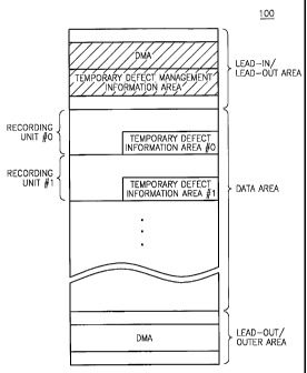
FIG. 3 illustrates an example of the structure of the disc 100
embodiments shown in FIGs. 2A and 2B. Referring to FIG. 3, a DMA is
3o present in at least one of the lead-in area, the lead-out area, and the
94
CA 02494148 2005-O1-31
WO 2004/015708 PCT/KR2003/001610
outer area of the disc 100. Also, a temporary defect management area
(TDMA) is formed in at least one of the lead-in area and the lead-out
area. A temporary defect information area is formed in the data area in
predetermined recording units.
s In general, information which relates to managing defects on the
disc 100 is recorded in the DMA. Such information includes a structure
of the disc 100 for defect management, the position of the defect
information, whether the detect management is performed, and the
position and size of the spare area. For a write-once disc 100, new data
to is recorded after previously recorded data when the previously recorded
data changes. !n general, when the disc 100 is loaded into a
recording/reproducing apparatus such as that shown in FIG. 1, the
apparatus reads data from the lead-in area and the lead-out area of the
disc 100 to determine how to manage the disc 100 and record or read
is data on or from the disc100. However, if the amount of data recorded in
the lead-in area increases, a longer time will be spent preparing the
recording or reproducing of the data after loading the disc 100.
Accordingly, an embodiment of the present invention proposes
temporary defect management information and temporary defect
2o information.
Specifically, only the temporary defect management information,
which is comparatively more important than the temporary defect
information, is recorded in the lead-in area. The temporary defect
information is recorded in the data area. It is preferable, but not
2s required, that new information is added to the previously recorded
information in the temporary defect information so that all recorded
information is accumulated therein. The recording/reproducing
apparatus reads last recorded temporary defect information and detects
defects throughout the disc 100 based on the read result. Thus,
3o information regarding the location of the last recorded temporary defect
CA 02494148 2005-O1-31
WO 2004/015708 PCT/KR2003/001610
information is recorded in temporary defect management information
area, where the temporary defect management information is recorded.
More specifically, the information regarding a defect occurring in a
recording unit #0 and information regarding a defect occurring in a
s recording unit #1 are recorded in the temporary defect management
information area #0 and the temporary defect management information
area #1, respectively. Defect management information for managing the
temporary defect information areas #0, #1 is recorded in the temporary
defect management information area. If no more data can be recorded
to on the disc 100 or if a user does not want to record more data on the
disc 100 ( i.e., the disc 100 needs to be finalized), the temporary defect
information recorded in the temporary defect information area and the
temporary defect management information recorded in the temporary
defect management information area are recorded in the DMA.
is The reason for recording the temporary defect management
information and the temporary defect information in the DMA again will
now be explained. When no more data will be recorded on the disc 100
(i.e., the disc 100 needs to be finalized), the temporary.defect
management information, which has been updated several times, and
2o the temporary defect information recorded in the data area are moved to
the DMA of the lead-in area. Thus, it is possible to have faster reading
of information recorded on the disc 100. Also, it is possible to increase
the reliability of the information by recording the defect management
information in a plurality of areas.
2s In this embodiment, the defect information recorded in the
temporary defect information areas #0 through #i-1 is again recorded in
temporary defect information area #i. Therefore, it is sufficient to read
the defect information from the last temporary defect information area
and to again record the read information in the DMA during the
3o finalization of the disc 100.
16
CA 02494148 2005-O1-31
WO 2004/015708 PCT/KR2003/001610
FIG. 4 illustrates structures of the disc 100 shown in FIG. 3.
Referring to FIG. 4, the DMA is formed in at least one of the lead-in area,
the lead-out area, and the outer area of the disc 100. When the disc
100 is the single record layer disc 100 as shown in FIG. 2A, the DMA is
s formed in at least of one of the lead-in area and the lead-out area.
When the disc 100 is the double record layer disc 100 as shown in FIG.
2B, the DMA is formed in at least one of the lead-in area, the lead-out
area, and the outer area of the disc 100. By way of example, if the disc
100 has a single record layer L0, DMAs are formed in both the lead-in
to area and the lead-out area, and if the disc 100 has two record layers L1,
L0, DMAs are formed in the lead-in area, the lead-out area, and the
outer area.
After recording the user data in the data area according to
recording operation #0, a temporary defect list (TDFL) #0, which is a
is temporary defect information area corresponding to the recording
operation #0, is disposed in the data area. Information regarding a
defect occurring in the user data recorded according to the recording
operation #0 is recorded in the TDFL #0. Similarly, the user data
according to recording operation #1 is recorded in the data area, and a
zo TDFL #1, which corresponds to the recording operation #1, is disposed
in the data area. A TDFL #2, which corresponds to recording operation
#2, is also disposed in the data area.
Temporary disc definition structure (TDDS), which is the
temporary defect management information for managing the TDFLs #0
2s through #n, is recorded in the temporary defect management information
area. The TDDSs #0 through #n correspond to the TDFL #0 through #n,
respectively. Using the TDDSs #0 through #n, it is possible to record
whether a defect is managed, the size of the spare area, and information
for managing TDFL #i in TDDS #i. Also, it is possible to record
3o information regarding the position of a defective area and the
17
CA 02494148 2005-O1-31
WO 2004/015708 PCT/KR2003/001610
corresponding position of the spare area, which is a substitute for the
defective area, in a TDFL #i.
For a high-density disc on which information of several dozen GB
bytes can be recorded, it is desirable, but not required, that a cluster is
s allocated to each TDDS #i, and four to eight clusters are allocated to the
TDFL #i. This allocation is because it is preferable to record new
information in units of clusters in order to update information when a
minimum physical unit of record is a cluster, although the amount of
TDDS#i, which is temporary defect management information, is just
io several K bytes. Meanwhile, it is preferable, but not required, that a
total
amount of defects allowed in the disc 100 is about 5 percent of the disc
recording capacity. For instance, the TDFL #i includes about four to
eight clusters considering that information of about 8 bytes is required to
record information regarding a defect and the size of a cluster is 64
is Kbytes.
According to an aspect of the invention, the verify-after-write
method can be performed in the TDDS #i and the TDFL #i. In this case,
when a defect is detected, information is recorded again in the
corresponding adjacent areas.
2o FIG. 5 is a diagram illustrating a process of recording a TDFL
according to an embodiment of the present invention. Here, a unit of
data may be processed in units of sectors or clusters. A sector denotes
a minimum unit of data that is managed in a file system of a computer or
an application, and a cluster denotes a minimum unit of data that can be
2s physically recorded on a disc at once. In general, one or more sectors
constitute a cluster.
There are two types of sectors: a physical sector and a logical
sector. The physical sector is an area where a sector of data is to be
recorded on the disc 100. An address for detecting the physical sector
18
CA 02494148 2005-O1-31
WO 2004/015708 PCT/KR2003/001610
is called a physical sector number (PSN). The logical sector is a unit of
sector for managing data in a file system or an application. An address
for detecting the logical sector is called a logical sector number (LSN).
A disc recording/reproducing apparatus such as that shown in FIG. 1
s detects the position of the data to be recorded on the disc 100 using the
PSN, and the whole part of data is managed in units of the LSNs in a
computer or an application in order to record data on the disc 100. The
relationship between the LSN and the PSN is changed by the controller 2
of the recording/reproducing apparatus, based on whether the disc
to contains a defect and an initial position of recording data.
Referring to FIG. 5, A denotes a data area in which the PSNs are
allocated to a plurality of sectors (not shown) in ascending order. In
general, each LSN corresponds to at least one of the PSNs, respectively.
However, since the LSNs are allocated to sectors, except for a defective
is sector, in ascending order, the correspondence between the PSNs and
the LSNs is not maintained when the disc 100 has a defective area, even .
if the size of a physical sector is the same as that of a logical sector.
Referring to FIG. 5, 1010 through 1090 denote units of data by
which a verifying work is performed after a recording work. In detail, a
ao recording apparatus records user data in section 1010, returns to the
start of the section 1010, and starts checking if the user data is
appropriately recorded or a defect occurs in the section 1010. If a
defect is detected, an area covering the defect and data recorded after
the defect in the section 1010 is designated as defect #1. Next, the
2s recording apparatus records the user data in section 1020, returns to the
start of the section 1020, and checks if the user data is appropriately
recorded or a defect occurs in the start. If a defect is detected, an area
covering the defect and data recorded after the defect in the section
1020 is designated as defect #2. Likewise, defect #3 is determined in
19
CA 02494148 2005-O1-31
WO 2004/015708 PCT/KR2003/001610
section 1030. However, since a defect is not detected in section 1040,
a defective area is not determined in section 1040.
Because the disc 100 according to an embodiment of the present
invention is a write-once disc 100, it is desirable, but not required, that
s data recorded after an area having a defect is not used and an area
covering data recorded after the defect is determined to be a defective
area as well as the area covering the defect. Assuming that the LSN i is
allocated to an area in which the data is recorded after an area having a.
defect in order to use the data, an area in which data is recorded after
io the area having the LSN i must be denoted as the LSN i-1 for data
reproduction. However, if there is a section to which the LSNs are not
allocated in ascending order, it is not easy to manage the logic sectors.
Therefore, in this embodiment, all of data areas after a defective area
are also regarded as being defective areas, thereby increasing the
1s efficiency of managing the logic sectors.
TDFL #0 is recorded in section 1050 when the recording operation
#0 is expected to end after the recording and verifying of the data in the
section 1040 (i.e., when a user presses an eject button of a recording
apparatus or recording of user data allocated in a recording operation is
2o completed). The TDFL #0 contains information regarding the defects #1
through #3 occurring in the sections 1010 through 1040. Similarly,
TDFL #1 is recorded in sector 1090 to,correspond to recording operation
#1 to contain information regarding defects #4 and #5 in sectors 1060
through 1080. The TDFL #0 also contains information regarding a part
2s of an area in which a user data is recorded according to the recording
operation #0, where the part having a defect and thus being designated.
as a defective area. Also, the TDFL #1 contains information regarding a
part of an area in which the user data recorded according to the
recording operation #1, where the part having a defect is designated as
3o another defective area. While not required in all aspect, the TDFL #1
CA 02494148 2005-O1-31
WO 2004/015708 PCT/KR2003/001610
further contains the information recorded in the TDFL #0 according to an
aspect of the invention.
FIGs. 6A and 6B illustrate data structures of a TDFL according to
an embodiment of the present invention. Referring to FIGS. 6A and 6B,
s information regarding defects #1 through #3 is recorded in TDFL #0.
The information regarding the defect #1 describes the position of the
defect #1, the information regarding the detect #2 describes the position
of the defect #2, and the information regarding the defect #3 describes
the position of the defect #3. Further, information regarding TDFL #0,
to which indicates the position of the TDFL #0, is further recorded in the
TDFL #0.
Since the user data is not recorded in the TDFL #0, it is not
required to read the information recorded in the TDFL #0 during
reproduction of the user data. That is, for the reproduction of the user
is data, it is meaningless to distinguish between defective area #i and the
TDFL #0 because the user data is not contained in these area. The
TDFL #0 contains the information regarding its position and thus can be
used as useful information, for example, to indicate during the
reproduction of the user data that the user data is not recorded in the
2o TDFL #0.
The TDFL #1 contains information regarding defects #4 and #5, in
addition to the information recorded in the TDFL #0. The TDFL #1 also
contains information regarding the position of the TDFL #1 for the same
reason that the position is indicated in the TDFL #0.
2s FIGs. 7A and 7B illustrate the data structures of information
regarding defect #i contained a TDFL and information regarding TDFL #i.
Referring to FIGs. 7A and 7B, the information regarding the defect #i
includes information regarding the state, the start, reserved, and end
positions of the defect #i. In general, the state information is flag
21
CA 02494148 2005-O1-31
WO 2004/015708 PCT/KR2003/001610
information that indicates whether a present area is a defective area in
which a defect occurs or is a TDFL in which is recorded temporary defect
information. In the information regarding the defect #i, the state
information is the flag information which indicates that the present area is
s a defective area. The start information represents the start of the
present area (i.e., the start of the defect #i). The end information
represents the end of the present area (i.e., the end of the defect #i).
The reserved is referred to as an area in which recording is pending to
record other information therein.
io The information regarding the TDFL #i includes information
regarding the state of and the start, reserved, and end positions of the
TDFL #i. In general, the state information is flag information that
indicates whether a present area is a defective area in which a defect
occurs or is a TDFL in which is recorded temporary defect information.
is In the information regarding the TDFL #i, the state information is the flag
information which indicates that the present area is a TDFL in which is
recorded temporary defect information.
FIG. 8 illustrates the data structure of temporary disc definition
structure (TDDS) #i. Referring to FIG. 8, the TDDS #i includes an
2o identifier, defect management mode information, a drive information
pointer, a TDFL #i pointer, which points out the position of the
corresponding TDFL #i, a user data physical area pointer, a user data
logical area pointer, an optimal power control (OPC) pointer, and disc
usage information.
2s The defect management mode information indicates whether
defect management is performed on the disc 100. For instance, the
information describes a spare area when defect management is
performed and does not describe the spare area otherwise. If defect
management is not required, the information provides this fact so that
3o more user data can be recorded in the spare area, which otherwise uses
22
CA 02494148 2005-O1-31
WO 2004/015708 PCT/KR2003/001610
about 5% of the disc recording capacity according to an aspect of the
invention. The drive information pointer describes the location (e.g., the
number of a first physical sector) of a drive information area (not shown)
of the disc 100 according to an aspect of the present invention.
s Drive information is obtained by conducting a test on the disc 100
with a certain disc drive, allowing the test to be skipped when data is
read from the disc 100, thereby rendering fast reading operations. In
other words, the drive information is created to use a certain drive
without testing the drive. In this embodiment, the drive information
io includes recording conditions, such as an identifier of a used drive and
the optimum record power. In the case of a write-once disc, data is
recorded in a new cluster whenever drive information is updated. Thus,
if information regarding an area of the disc 100 in which the next drive
information is to be recorded is known in advance, it is possible to
is reduce time required to perform preliminary operations in order to read or
reproduce data from or on the disc 100. For this reason, it is useful to
record such drive information on a disc.
The TDFL #i pointer indicates the position of an area of the disc
100 where the TDFL #i is recorded (e.g., the number of a first physical
2o sector of TDFL #i). The user data physical area pointer indicates the
end (e.g., the number of the last physical sector) of a data area in which
user data is physically recorded. The user data logical area pointer
indicates the end part (e.g., the number of the last logical sector) of the
data area in which user data is logically recorded. It is possible to detect
2s the start of the data area where recording of the user data begins during
a next recording operation, using the user data physical area pointer and
the user data logical area pointer. The OPC pointer describes the
location of a test area for detecting the optimum power control. The
OPC pointer can also be used as information that provides a next area
3o available when different types of drives are driven by different OPCs.
23
CA 02494148 2005-O1-31
WO 2004/015708 PCT/KR2003/001610
The disc usage information specifies whether the disc 100 is finalized
(i.e., whether user data can be further recorded in the data area).
FIG. 9 illustrates an embodiment of the data structure of TDFL #i.
Referring to FIG. 9, the TDFL #i includes an identifier, a TDDS #i pointer,
s information regarding defect #n, information regarding defect #n+1, and
so on. The information regarding defect #n includes information
regarding start and end positions of defect #n in state information.
The TDDS #i pointer indicates the position of an area in which is
recorded a corresponding TDDS #i. For instance, the TDDS #i pointer
to can indicate the number of a first physical sector of the TDDS #i.
Information regarding the position of the TDFL #i included in the TDDS #i
and information regarding the position of the TDDS #i included in the
TDDS #i specify the positions of the TDFL #i and the TDDS #i which are
a pair of information. Thus, the above two different information can be
~s used to verify the availability of information recorded in the TDFL #i and
the TDDS #i.
The state information, which is the information regarding defect #n,
describes whether a certain area is an actual defective area or an area
where defect management information is recorded. The inclusion of the
2o information regarding the defect #n into the state information is optional.
The information regarding the start and end positions of the defect #n
may be recorded with the number of a first physical sector and the
number of the last physical sector of the defective area, respectively.
The information regarding defect #n+1 is also recorded using the method
2s of recording the information regarding the defect #n.
In an embodiment of the invention, the verify-after-write method is
performed for every several clusters. If the verify-after-write method is
performed for every single cluster, the size of an area, which is
24
CA 02494148 2005-O1-31
WO 2004/015708 PCT/KR2003/001610
designated as a defective area, is determined to be a cluster, and thus,
the number of the last physical sector of the area need not be recorded.
FIG. 10 illustrates the data structure of a disc definition structure
(DDS) to be recorded in the DMA shown in FIGs. 3 and 4. Referring to
s FIG. 10, the DDS includes an identifier, defect management mode
information, a drive information pointer, a DFL pointer which specifies the
position of a corresponding DFL, a user data physical area pointer, a
user data logical area pointer, an OPC pointer, and disc usage
information.
to The defect management mode information indicates whether
defect management is performed. This information describes that a
spare area is not formed in the disc 100 according to the presenfi
invention when the defect management is not performed, and describes
that a spare area is formed otherwise. The drive information pointer
is specifies the position of a drive information area (not shown) of the disc
100. For example, the drive information pointer can specify the number
of a first physical sector of the drive information area.
Drive information is obtained by conducting a test on the disc 100
with a certain drive, allowing the test to be skipped when data is read
2o from the disc 100, thereby rendering fast reading operations. In other
words, the drive information is created to use a certain drive without
testing the drive. In this embodiment, the drive information includes
recording conditions such as an identifier of a used drive and the
optimum record power. In the case of a write-once disc, data is
2s recorded in a new cluster whenever drive information is updated. Thus,
if information regarding an area of the disc 100 in which the next drive
information is to be recorded is known in advance, it is possible to
reduce time required to perform preliminary operations in order to read or
reproduce data from or on the disc 100. For this reason, it is useful to
3o record such drive information on a disc.
CA 02494148 2005-O1-31
WO 2004/015708 PCT/KR2003/001610
The DFL pointer specifies the position of an area in which DFL is
recorded (e.g., the number of a first physical sector of the DFL). The
user data physical area pointer indicates the end position of an area of a
data area in which user data is physically recorded (e.g., the number of
s the last physical sector of the area in which the user data is recorded).
The user data logical area pointer indicates the end position of an area
of a data area in which user data is physically recorded (e.g., the number
of the last physical sector of the area in which the user data is recorded).
With the user data physical area pointer and the user data logical area
io pointer, it is possible to know the start of an area in which user data is
to
be recorded during a next recording operation. The OPC pointer
specifies the position of a test area for detecting the optimum power
control. The OPC pointer can also be used as information that provides
a next area available when different types of drives are driven by
is different OPCs. The disc usage information specifies whether the disc
100 is finalized (i.e., whether user data can be further recorded in the
data area).
FIG. 11 illustrates an embodiment of the data structure of a defect
list (DFL) to be recorded in the DMA shown in FIGs. 3 and 4. Referring
2o to FIG. 11, the DFL includes an identifier, a DDS pointer, information
regarding defect #n, and information regarding defect #n+1. The
information regarding defect #n includes information regarding the start
and end positions of defect #n in state information. Here, information
regarding defect #i may be information regarding the aforementioned
2s TDFL #i.
The DDS pointer points out the position of an area in which a
corresponding DDS is recorded (e.g., the number of a first physical
sector of the DDS). Information regarding the position of the DFL
included in the DDS and information regarding the position of the DDS
3o included in the DFL, specify the positions of the DFL and the DDS which
26
CA 02494148 2005-O1-31
WO 2004/015708 PCT/KR2003/001610
are a pair of information. Thus, the above two different information can
be used to verify the availability of information recorded in the DFL and
the DDS.
The state information, which is the information regarding defect #n,
s describes whether a certain area is an actual defective area or an area
where defect management information is recorded. The inclusion of the
information regarding the defect #n into the state information is optional.
The information regarding fihe start and end positions of the defect #n
may be recorded with the number of a first physical sector and the
io number of the last physical sector of the defective area, respectively.
The information regarding defect #n+1 is also recorded using the method
of recording the information regarding the defect #n.
In an embodiment of the invention, the verify-after-write method is
performed for every several clusters. If the verify-after-write method is
is performed for every single cluster, the size of an area, which is
designated as a defective area, is determined to be a cluster, and thus, ..
the number of the last physical sector of the area need not be recorded.
Hereinafter, embodiments of a disc defect management method
according to the present invention will be described.
2o FIG. 12 is a flowchart illustrating a disc defect management
method according to an embodiment of the present invention. Referring
to FIG. 12, in action 1201, a recording apparatus records defect
information regarding data, which is recorded according to a first
recording operation, as first temporary defect information in a data area
2s of a disc, so as to perform disc defect management. In action 1202, the
recording apparatus records the first temporary defect information and
defect information regarding data, which is recorded according to a
second recording operation, as second temporary defect information in
the data area. In action 1203, the recording apparatus records defect
27
CA 02494148 2005-O1-31
WO 2004/015708 PCT/KR2003/001610
management information for managing the first and second temporary
defect information in a temporary defect management information area.
In detail, action 1203 is performed by sequentially recording the first
temporary defect information, the defect management information for
managing the first temporary defect information, the first temporary
defect management information, the second temporary defect
information, the defect management information for managing the
second temporary defect information, and the second temporary defect
management information.
io As described, the method only records two temporary defect
information and two temporary defect management information for the
sake convenience. However, it is understood there is no limit to the
number of temporary defect information and defect management
information which can be recorded. If the number is increased,
is temporary defect information is accumulatively recorded in the temporary
defect management information area (i.e., all of previously recorded
temporary defect information are recorded together with newly recorded
temporary defect information).
During finalization of the disc, a last recorded temporary defect
2o information and temporary defect management information may be
either moved from the temporary defect management information area to
a defect management area (DMA), or be maintained to be recorded in
the temporary defect management information area. If the latter
location is selected, a disc drive accesses the temporary defect
2s management information area and reads the last recorded temporary
defect information therefrom so as to detect a defective area of the disc.
FIG. 13 is a flowchart illustrating a disc defect management
method according to another embodiment of the present invention.
Referring to FIG. 13, in action 1301, a recording apparatus records
3o defect information regarding data, which is recorded according to a first
28
CA 02494148 2005-O1-31
WO 2004/015708 PCT/KR2003/001610
recording operation, as first temporary defect information in a data area
of a disc, so as to perform disc defect management. In action 1302, the
recording apparatus records defect management information for
managing the first temporary defect information as first temporary defect
s , management information in a temporary defect management information
area which is present in at least one of a lead-in area and a lead-out
area of the disc. In action 1303, the recording apparatus records the
temporary defect information and defect information regarding data,
which is recorded according to a second recording operation, as second
io temporary defect information in the data area. In action 1304, the
recording apparatus records management information for managing the
second temporary defect information as second temporary defect
management information in the temporary defect management
information area. In action 1305, it is checked whether finalization of the
is disc is required is checked.
In action 1306, if it is determined in action 1305 that finalization of
the disc is not required, actions 1301 through 1304 are repeated while
increasing indexes given to the recording operation, the temporary defect
information, and the temporary defect management information by 1. It
2o is understood that the indexing could be numbers other than 1 or
non-integers so long as the index changes so as to reflect different
recording operations being performed. While not required in all aspects,
all of previously recorded temporary defect information are
accumulatively recorded whenever new temporary defect information is
2s recorded.
In action 1307, if it is determined in action 1305 that the disc is
required to be finalized, a last recorded one of temporary defect
management information and temporary defect information, which have
been recorded until action 1305, are recorded in a defect management
3o area (DMA). In other words, the last recorded temporary defect
29
CA 02494148 2005-O1-31
WO 2004/015708 PCT/KR2003/001610
management information and temporary defect information are recorded
as final defect management information and defect information in the
DMA. The final defect management information and defect information
may be repeatedly recorded to increase the reliability of data detection.
s Further, the verity-after-write method may be performed on the
final defect management information and defect information according to
an embodiment of the invention. If a defect is detected from these
information, an area of the disc in which the defect occurs and data
recorded after the area having the defect may be regarded as being
to unavailable (i:e., they are designated as a defective area), and the final
defect management information and defect information may be again
recorded after the defective area. FIG. 14 is a flowchart illustrating a
method of managing a defect in a disc according to yet another
embodiment of the present invention. Referring to FIG. 14, a recording
is apparatus records user data on a data area of a disc in units of data to
facilitate the verify-after-write method, in action 1401. In action 1402,
the data recorded in action 1401 is verified to detect an area of the disc
in which a defect exists. In action 1403, the controller 2 of FIG. 1
creates information for designating an area covering the area having the
2o defect and data recorded after the area having the defect, as a defective
area. In action 1404, the controller 2 stores the created information as
first temporary defect information in the memory 3 of FIG. 1. In action
1405, it is checked whether a recording operation is expected to end. If
it is determined in action 1405 that the recording operation is not likely to
2s end, actions 1401 through 1404 are repeated before the end of the
recording operation.
In action 1406, if it is determined in action 1405 that the recording
operation is likely to end (i.e., when the recording of the user data is
complete by a user input or according to the recording operation), the
3o controller 2 reads the first temporary defect information from the memory
CA 02494148 2005-O1-31
WO 2004/015708 PCT/KR2003/001610
3 and records the first temporary defect information in a first temporary
defect information area TDFL #0 of the data area. In action 1407,
information for designating the first temporary defect information area
TDFL #0 as a defective area is further recorded in the first temporary
s defect information area TDFL #0. In action 1408, the controller 2
records management information for managing the first temporary defect
information area TDFL #0 as first temporary defect management
information TDDS #0 in a temporary defect management information
area.
io In action 1409, it is checked whether the disc is to be finalized. In
action 1410, if it is determined in action 1409 that the disc is not required
to be finalized, actions 1401 through 1408 are repeated before the
finalization while increasing indexes given to the temporary defect
information, the temporary defect information area, and the temporary
is defect management information by 1. Here, all of previously recorded
temporary defect information are accumulatively recorded whenever new
temporary defect information is recorded. It is understood that other
numbers (including non-integers) could be used for the index so long as
the index changes reflect different recording operations being performed.
2o In action 1411, if it is determined in action 1409 that finalization of
the disc is required, a last recorded temporary defect information TDFL #i
and temporary defect management information TDDS #i are recorded as
final defect information DFL and defect management information DDS,
respectively, in a defect management area (DMA). The final defect
2s information (DFL) and defect management information (DDS) may be
repeatedly recorded in the DMA several times so as to increase the
reliability of data detection.
Further, the verify-after-write method may be performed on the
final defect information (DFL) and final defect management information
30 (DDS) according to an aspect of the invention. If a defect is detected
31
CA 02494148 2005-O1-31
WO 2004/015708 PCT/KR2003/001610
from the DFL and DDS, an area covering an area of the disc in which the
defect occurs and data recorded after the area having the defect, may be
regarded as being unavailable (i.e., be designated as a defective area),
and the DFI_ and DDS may be again recorded after the defective area.
s The aforementioned defect management may be embodied as a
computer program thafi can be run by a computer. Codes and code
segments, which constitute the computer program, can be easily
reasoned by a computer programmer in the art. The program is stored
in a computer readable medium. When the program is read and run by
to a computer such as the controller 2 shown in FIG. 1, the defect
management is performed. Here, the computer-readable medium may
be on a magnetic recording medium, an optical recording medium, a
carrier wave medium or any other medium from which a computer can
recognize a program. Moreover, the computer can be a general or
is special purpose computer and can utilize the program encoded on
firmware.
Industrial Applicability
As described above, the present invention provides a defect
2o management method that is applicable to a recordable disc, such as a
write-once disc. In the method, a temporary defect information area is
included in a data area of a disc, and therefore, defect information is
accumulatively recorded in the temporary defect information area
regardless of the disc recording capacity. Also, during finalization of the
2s disc, only temporary defect information is read from the last temporary
defect information area and the read information is recorded in a DMA,
thereby enabling efficient use of the DMA whose recording capacity is
limited. Accordingly, it is possible to record user data even on a
write-once disc while performing defect management thereon, thereby
3o backup operations can be more stably performed without interruptions.
32
CA 02494148 2005-O1-31
WO 2004/015708 PCT/KR2003/001610
In particular, a pointer, which specifies the position of a
corresponding TDDS #i, is recorded in TDFL #i and a pointer, which
specifies the position of TDFL #i, is recorded in the TDDS #i. Therefore,
it is possible to crosscheck the relationship between the TDFL #i and the
s TDDS #i. For the same reason, it is possible to crosscheck the
relationship between a DDS and a DFL. Further, defect management
mode information is contained in the TDDS #i and the DDS and allows
selective defect management, thereby successfully performing recording
operations irrespective of recording environment conditions.
to In addition, it is understood that, in order to achieve a recording
capacity of several dozen gigabytes, the recording and/or reproducing
unit 1 shown in FIG. 1 could include a low wavelength, high numerical
aperture type unit usable to record dozens of gigabytes of data on the
disc 100. Examples of such units include, but are not limited to, those
is units using light wavelengths of 405 nm and having numerical apertures
of 0.85, those units compatible with Blu-ray discs, and/or those units
compatible with Advanced Optical Discs (AOD).
While described in terms of a write-once disc, it is understood that
the method can be used with rewritable media or where the medium has
2o write-once and rewritable portions.
Although a few embodiments of the present invention have been
shown and described, it would be appreciated by those skilled in the art
that changes may be made in this embodiment without departing from
the principles and spirit of the invention, the scope of which is defined in
2s the claims and their equivalents.
33