Note: Descriptions are shown in the official language in which they were submitted.
CA 02495994 2008-12-18
WO 2004/019718 PCT/US2003/023256
INDEXABLE SHOE CLEAT WITH IMPROVED TRACTION
BACKGROUND OF THE INVENTION
Technical Field
The present invention pertains to cleats for use with shoes worn on turf and
other
surfaces. In particular, the present invention pertains to a golf cleat that
provides traction
on various types of surfaces and for specific purposes.
Discussion of Related Art
The need for providing improved traction elements for the soles of shoes on
turf
surfaces is well known in the art, particularly in the field of sports such as
football,
baseball, soccer and golf. In many sports, particularly golf, the need for
providing
improved traction elements must be considered in combination with limiting the
wear and
tear on the playing turf that can be caused by the traction elements.
In recent years, there has been a change from using penetrating metal spikes
for
golf shoes to removable plastic cleats that are much more turf-friendly and
less harmful
to clubhouse floor surfaces. However, the challenge with utilizing plastic
cleats is to
design a cleat having suitable traction on turf surfaces while being suitably
protected
from wear and tear due to contact with hard surfaces such as asphalt or
concrete.
An example of a removable plastic cleat having desirable traction
characteristics
is described and illustrated in U.S. Patent No. 6,167,641 (McMullin).
In the McMullin patent there is
disclosed a removable cleat having a hub with an upper surface facing the shoe
sole and a
bottom surface facing away from the sole. A hub attachment member extends from
the
upper surface for attaching the hub to one of plural sole-mounted attachment
means.
Traction elements extend outwardly and downwardly from the hub, each traction
element
being deflectably attached to the hub so that it pivotally and resiliently
deflects toward
the sole when it encounters a hard surface. When used on grass or turf, the
traction
1
CA 02495994 2005-02-17
WO 2004/019718 PCT/US2003/023256
element deflection results in grass blades being trapped between the upper
surface of the
traction elements and the sole of the shoe, thereby grabbing the grass blades
and
providing the desired traction function. In addition, the deflection serves to
minimize
abrasive wear of the traction elements on hard surfaces such as golf paths.
Importantly,
the traction elements do not penetrate the surface on which they are used,
thereby
minimizing damage to the turf. Although this cleat is effective for the
purpose described,
improvements are desirable in certain aspects of the cleat performance. For
example, on
hard surfaces such as found in a tee box, dirt path, concrete, asphalt, tile,
etc., the
deflecting traction elements provide only minimal, if any, traction since each
traction
element is designed to spread and flex on the ground surface.
Another removable plastic cleat for golf shoes is disclosed in WO 01/54528 to
Japana Co., LTD. The Japana golf shoe cleat includes a plurality of long and
short legs
protruding outwardly from a body of the cleat to contact a turf surface when
connected to
the sole of a shoe. The long legs and short legs are disposed along a
periphery of the
cleat body in an alternating configuration, where one or more long legs are
provided
between two adjacent short legs. The long legs are provided to provide
traction on turf
whereas the short legs press down hard on the grass and chiefly support the
weight
bearing on the cleat. The Japana cleat is limited in that it only discloses
symmetrically
alternating long and short legs extending from the shoe sole. Thus, the
axially symmetric
Japana cleat is not capable of being indexed or oriented in different
positions with respect
to the shoe sole in order to selectively position the weight bearing shorter
legs and the
penetrating longer legs in different alignments based upon cleat applications
requiring
different directions and levels of traction.
It is therefore desirable to provide a cleat that minimizes damage to turf
surfaces
yet provides suitable traction for the shoe on harder surfaces as well as
different levels of
traction at different portions of the shoe based upon selected orientations of
the shoe cleat
with respect to the shoe sole.
2
CA 02495994 2005-02-17
WO 2004/019718 PCT/US2003/023256
OBJECTS AND SUMMARY OF THE INVENTION
Therefore, in light of the above, and for other reasons that become apparent
when
the invention is fully described, an object of the present invention is to
provide a shoe
cleat with enhanced traction while minimizing damage to turf surfaces.
It is another object of the present invention to provide a shoe cleat that
does not
easily wear on hard surfaces such as concrete or asphalt yet provides a
suitable level of
traction for such hard surfaces.
It is a further object of the present invention to provide a shoe cleat that
is
indexable to facilitate a variety of orientations of the cleat with respect to
the shoe sole.
The aforesaid objects are achieved individually and in combination, and it is
not
intended that the present invention be construed as requiring two or more of
the objects to
be combined unless expressly required by the claims attached hereto.
In accordance with the present invention, an indexable shoe cleat is provided
including a hub with at least one dynamic traction element and at least one
static traction
element extending from an exposed surface of the hub and away from the sole of
a shoe
when the cleat is secured to the shoe sole, where the traction elements are
asymmetrically
positioned about a central axis of the hub. The dynamic traction element is
configured to
deflect toward the shoe sole when the shoe engages a ground surface to reduce
damage to
turf surfaces as well as to minimize wear and tear to the cleat on harder
surfaces. The
static traction element is configured to substantially resist deflection when
the shoe
engages the ground surface and to provide a suitable bearing for supporting
weight
applied to the shoe. A cleat comlector is preferably disposed on a surface of
the hub that
opposes the exposed surface to connect the cleat to the shoe sole. The cleat
connector is
suitably configured to connect the cleat to the shoe sole so as to align each
of the static
and dynamic traction elements in a desired orientation with respect to the
shoe. A
plurality of shoe cleats may further be selectively indexed on the shoe to
vary the
orientations of the traction elements of each cleat with respect to the shoe
sole based
upon a particular application and/or user preference.
The above and still furtlier objects, features and advantages of the present
invention will become apparent upon consideration of the following
definitions,
descriptions and descriptive figures of specific embodiments thereof wherein
like
3
CA 02495994 2005-02-17
WO 2004/019718 PCT/US2003/023256
reference numerals in the various figures are utilized to designate like
components.
While these descriptions go into specific details of the invention, it should
be understood
that variations may and do exist and would be apparent to those skilled in the
art based on
the descriptions herein.
BRIEF DESCRIPTION OF THE DRAWINGS
Fig. 1 is a bottom view in plan of an exemplary shoe cleat in accordance with
the
present invention.
Fig. 2 is a side view in elevation of the shoe cleat of Fig. 1.
Fig. 3 is a bottom view in plan of an alternative embodiment of an exemplary
shoe cleat in accordance with the present invention.
Fig. 4 is a bottom view in plan of another alternative embodiment of an
exemplary shoe cleat in accordance with the present invention.
Fig. 5 is an elevated side view in partial section of the shoe cleat of Fig. 1
including a cleat connector and a connection member that engages with the
cleat
connector.
Fig. 6 is a bottom view of a pair of shoes to which are secured a number of
shoe
cleats substantially similar to the shoe cleat of Fig. 1.
DETAILED DESCRIPTION OF PREFERRED EMBODIMENTS
The present invention includes a cleat that is secured to a shoe sole to
enhance
traction of the shoe. Referring to Figs. 1 and 2, shoe cleat 1 includes a
generally circular
hub 2 having a top surface 3 and a bottom surface 4. However, the hub is not
limited to a
circular configuration but may have any suitable geometric configuration
including,
without limitation, rounded, elliptical, rectangular, triangular, etc. It is
to be understood
that the terms "top surface" and "bottom surface" as used herein refer to
surfaces of the
shoe cleat that face toward or away, respectively, from the shoe sole. The top
surface of
the hub may be connected to the shoe sole in any suitable manner to secure the
cleat to
the shoe. Preferably, the shoe cleat is removably connected to the shoe sole
with a cleat
connector such as the connector illustrated in Fig. 5 and described below. The
cleat is
preferably constructed of any suitable plastic materials, including, without
limitation,
4
CA 02495994 2005-02-17
WO 2004/019718 PCT/US2003/023256
polycarbonates, polyamides (e.g., nylon), polyurethanes, natural or synthetic
rubbers
(e.g., styrene-butadiene), and other elastomeric polyolefins.
Extending from the bottom surface periphery of the hub in a cantilevered
manner
is a plurality of traction elements. The traction elements engage the ground
surface when
the shoe to which the cleat is attached is brought down into contact with that
surface.
The traction elements include a set of four sequentially aligned and
substantially evenly
spaced dynamic traction elements 10 and a set of four sequentially aligned and
substantially evenly spaced static traction elements 30. However, it is noted
that any
suitable spacing distance (e.g., even or uneven) between traction elements may
be
utilized. The dynamic traction elements are designed to resiliently pivot with
respect to
the hub and deflect toward the shoe sole when the shoe engages a ground
surface as
described below, whereas the static traction elements remain substantially
rigid and are
resistant to deflection upon engaging the ground surface.
The dynamic traction elements 10 are generally aligned in a set along a first
half
of the hub perimeter, whereas the static traction elements 30 are generally
aligned in a set
along the remaining half of the hub perimeter. However, it is noted that any
suitable
number of sets of traction elements including any suitable number of static or
dynamic
traction elements may be oriented in axial asymmetry in any suitable manner
along the
hub bottom surface. For example, in an alternative embodiment depicted in Fig.
3, cleat
100 includes a set of four dynamic traction elements 120 and a set of three
static traction
elements 130. Other embodiments may include sets having a greater number of
static
traction elements than sets with dynamic traction elements as well as multiple
sets of one
or both of the static and dynamic traction elements. Another exemplary
einbodiment of a
shoe cleat with multiple sets of traction elements is depicted in Fig. 4,
where cleat 150
includes two sets of dynamic traction elements 160 and two sets of static
traction
elements 170. Specifically, cleat 150 includes a set of three dynamic traction
elements, a
set of two dynamic traction elements, and two sets of two static traction
elements. The
selection of a specific cleat design, including a selected number of each type
of traction
element as well as a selected orientation of the traction elements in sets on
the hub, may
depend upon a specific application in which the cleat will be utilized and the
type or
amount of traction that is desired for that application.
5
CA 02495994 2005-02-17
WO 2004/019718 PCT/US2003/023256
Each dynamic traction element 10 includes a generally rectangular upper leg I
1
extending at an obtuse angle (e.g., approximately 155 ) from a peripheral side
portion of
hub 4 and a generally polyhedral lower leg 12 that extends at an obtuse angle
(e.g.,
approximately 135 ) from the upper leg and tapers toward its terminal end,
where the
lower leg is greater in longitudinal dimension than the upper leg. Each lower
leg 12
terminates at a foot 13 that has a rounded, convex curvature with respect to
the ground
surface when the cleat is attached to a shoe. The dynamic traction elements 10
have
substantially similar dimensions, with their feet 13 all residing in and
defining a plane
that is generally parallel to the bottom surface of the hub. The dimensional
design and/or
materials of construction of dynamic traction elements 10 are selected to
permit a
selected degree of deflection of the dynamic traction elements when the cleat
is forced
against the ground surface as described below. Preferably, the radial
dimension of the
hub is reduced to form a concave hub perimeter on either side of each dynamic
traction
element so as to enhance deflection of these elements when the cleat engages a
ground
surface.
Each upper leg 11 is partially defined by a generally rectangular outer
surface 14
extending from the periphery of the top surface of the hub to a generally
trapezoidal outer
surface 15 defining a portion of each corresponding lower leg 12. It is to be
understood
that the terms "inner surface" and "outer surface" as used herein refer to
surfaces of the
static and dynamic traction elements that face toward or away, respectively,
from the
central axis of the hub (i.e., the axis extending between the top and bottom
surfaces of the
hub through its center). Opposing trapezoidal side surfaces 19 of each lower
leg 12 are
disposed between the inner and outer surfaces of the lower leg and extend from
corresponding side surfaces of upper leg I 1 to foot 13. The outer surface 14
of the upper
leg includes a pair of longitudinally extending triangular ridges 16, where
each ridge 16
extends from the junction of the upper leg outer surface with the hub top
surface to the
junction of the upper leg outer surface with the lower leg outer surface 15.
Similarly,
lower leg outer surfaces 15 include a number of outwardly extending ramped
sections 18
that extend in a direction toward the upper legs. The ridges and ramped
sections of the
upper and lower leg outer surfaces provide enllanced traction for the dynamic
traction
elements as described below. Alternatively, it is noted that any number of
suitable
6
CA 02495994 2005-02-17
WO 2004/019718 PCT/US2003/023256
protrusions may be provided on the outer surfaces of the dynamic traction
elements to
enllance traction as described below.
Each lower leg 12 of the dynamic traction elements is further partially
defined by
an inner surface 20 extending from the hub bottom surface to foot 13 a't the
free end of
the lower leg. Each inner surface 20 has a generally trapezoidal geometry with
a slight
convex curvature. Preferably, but not necessarily, gussets 21 are provided
along the
interior surfaces of the lower legs to assist in biasing the deflected dynamic
traction
elements back to their original positions when the shoe to which the cleat is
attached is
lifted from the ground surface. Each gusset 21 is generally triangular, with
one side of
the gusset attaching to a portion of the lower leg inner surface of a
corresponding
dynamic traction element and another side of the gusset attaching to a portion
of the hub
bottom surface. The gussets are preferably resilient to act as springs,
pulling the dynamic
traction elements back into their upright, cantilevered positions when the
shoe is raised
from a ground surface. In addition, each gusset preferably acts as a wear
surface when
the dynamic traction elements are deflected toward the shoe sole, so that even
the inner
surfaces of these traction elements are substantially protected from abrasion.
Static traction elements 30 each include a generally rectangular upper leg 31
extending at an obtuse angle (e.g., about 155 ) from a peripheral side portion
of hub 4 and
a generally rectangular lower leg 32 extending at an obtuse angle (e.g., about
135 ) from
the upper leg. Each lower leg 32 terminates at a foot 33 that has a rounded,
convex
curvature with respect to the ground surface when the cleat is attached to a
shoe. The
static traction elements 30 have substantially similar dimensions, with their
feet 33 all
residing in and defining a plane that is generally parallel to the bottom
surface of the hub.
That plane is also parallel to the plane defined by feet 13 but resides closer
to hub 4.
Accordingly, the static traction elements are all shorter in longitudinal
dimension than the
dynamic traction elements and thus extend a shorter distance from the bottom
surface of
liub 4. It is noted that the dimensions and/or materials of construction of
static traction
elements 30 are selected to prevent or substantially resist deflection of the
static traction
elements when the cleat engages a ground surface. The radial dimension of the
hub
remains substantially constant between adjacent static traction elements to
further support
and prevent or resist deflection of these elements. The feet of the static
traction elements
7
CA 02495994 2005-02-17
WO 2004/019718 PCT/US2003/023256
are also preferably larger in dimension than the feet of the dynamic traction
elements to
enhance the weight bearing capabilities of the static traction elements when
the shoe is
pressed against the ground surface while preventing or minimizing puncturing
or
indenting of the turf surface.
Each upper leg 31 of the static traction elements is partially defined by a
generally
rectangular outer surface 34 extending from the periphery of the top surface
of the hub to
a generally rectangular outer surface 35 defining a portion of each
corresponding lower
leg 32. The outer surface 34 of the upper leg includes a pair of
longitudinally extending
triangular ridges 36, where each ridge 36 extends from the junction of the
upper leg outer
surface with the hub top surface to the junction of the upper leg outer
surface with the
lower leg outer surface 35. These triangular ridges provide some enhanced
traction for
the static traction elements as described below, although not to the same
extent as the
ridges and rainped sections for the dynamic traction elements. Each lower leg
12 of the
dynamic traction elements is further partially defined by an inner surface 38
extending
from the hub bottom surface to foot 33 at the free end of the lower leg. Each
inner
surface 38 of the static traction elements has a generally rectangular
geometry with a
slight concave curvature.
The arrangement of the sets of static and dynamic traction elements on the hub
in
the manner described above yields a cleat that is asymmetric about the hub
central axis,
with static traction elements disposed along one half of the hub perimeter and
dynamic
traction elements disposed along the other half. This axially asymmetric
design allows
the cleat .to be indexed in a desired angular orientation along the surface of
the shoe sole
to achieve optimum positions for the static and dynamic traction elements and
provide for
a variety of enhanced traction effects for different applications as described
below. The
asymmetry may also be described in terms of the sets of dynamic and static
traction
elements; that is, the dynamic and static sets are positioned asymmetrically
with respect
to one another, both about the hub axis and about any and all hub diameters.
In the
embodiment illustrated in Figs.l and 2, the asymmetry is most evident at the
feet 13 and
33 since in this embodiment it is the length of the traction elements that
determine their
dynamic and static function.
8
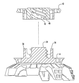
CA 02495994 2008-12-18
A precise orientation of the cleat may be facilitated with a cleat connector
as
illustrated in Fig. 5. Cleat connector 6 extends from the top surface of the
hub and is
configured to releasably engage with a recess or receptacle 40 in shoe sole
42. The cleat
comiector is substantially similar in design and function to the cleat
connecting member
described in U.S. Patent Application Publication No. US2002/0056210 to Kelly
et al.
However, it is
noted that any other suitable cleat connector may be utilized to orient the
traction
elements of the cleat in any desired manner with respect to the shoe cleat in
accordance
with the present invention. Briefly, cleat connector 6 includes an externally
threaded
spigot 34 as well as additional projections 36 that align and engage with an
internally
threaded recess 43 and other corresponding elements disposed within a
receptacle 40 of
the shoe sole 42 as described in the Kelly et al. published application. As
further
described in Kelly et al., the cleat connector and receptacle elements
appropriately
engage with each other by twisting the cleat connector within the receptacle
to lock it
therein, which in turn aligns the cleat in a specific orientation with respect
to the shoe.
The cleat connector elements are suitably aligned on the hub and/or the
receptacle
elements are suitably aligned within the receptacle to achieve a selected
orientation of the
cleat traction elements with respect to the shoe sole when the cleat connector
is locked
within the shoe receptacle.
In operation, cleat 1 is connected to the sole of a shoe by engaging cleat
connector
6 with receptacle 40 of the shoe sole and twisting the cleat connector in a
suitable manner
to lock the cleat to the shoe, which in turn orients the static and dynamic
traction
elements of the cleat in a desired alignment for a particular activity. When
the weight of
the user is applied to the shoe by pressing the shoe against a ground surface,
dynamic
traction elements 10 are the first to contact the surface. The dynamic
traction elements
deflect toward the shoe sole as the shoe is pressed further toward the ground
surface,
allowing static traction elements 30 to contact the surface when the dynamic
traction
elements have achieved a certain deflected orientation. Static traction
elements 30
substantially maintain their original cantilevered orientation and bear much
of the weight
applied to the shoe. When the user raises the shoe fronl the ground surface,
the dynamic
9
CA 02495994 2008-12-18
WO 2004/019718 PCT/US2003/023256
traction elements resiliently flex back to their original positions,
preferably with the help
of gussets 21.
The slight convex curvature of feet 13 and 33 of the traction elements spreads
the
contact over a greater area than a lineal edge and thereby prevents or
substantially limit
penetration, puncturing or indenting of the traction elements into turf
surfaces. This
curvature further facilitates the sliding of feet 13 along a surface when the
dynamic
traction elements are deflected toward the shoe sole. On harder surfaces
(e.g., tee boxes
or paved surfaces), the static traction elements provide enhanced traction for
the cleat by
resisting deflection and immediately bearing the weight that is applied to the
shoe, while
the dynamic traction elements deflect and are protected from serious abrasion
by their
gussets and the static elements.
The ridges and ramped sections of the dynamic traction elements provide
additional traction in turf surfaces by entangling and/or trapping grass
blades to limit or
prevent slipping of the cleat when engaged with the turf surface. In
particular, the
dynamic traction elements are preferably designed to allow both the upper and
lower legs
of each element to deflect against the shoe sole (or any extended portion of
the hub) when
sufficient weight is applied to the shoe. When pressed against the shoe sole,
ramped
sections 18 disposed on each lower leg 12 and ridges 16 disposed on each upper
leg 11
essentially trap and lock grass blades between outer surfaces 14 and 15 of the
upper and
lower legs of each dynamic traction element and the shoe sole to resist
sliding of the cleat
on the turf surface. The static traction elements are structurally unable to
deflect toward
the shoe sole, and are therefore incapable of trapping grass blades in a
manner similar to
the dynamic traction elements. However, the ridges of the static traction
elements
provide an uneven outer surface that can entangle grass blades during contact
with the
turf, thus providing some enhanced level of traction.
In addition, the shoe sole may contain recesses that correspond and cooperate
with the dynamic traction element upper and lower legs and their ridges and
ramped
sections to provide a greater trapping and locking effect for grass blades by
the cleat.
Exemplary embodiments of recesses on the shoe sole that cooperate with
deflecting
dynamic traction elements of a cleat are described in U.S. Patent Application
Serial No.
10/195,3151
CA 02495994 2005-02-17
WO 2004/019718 PCT/US2003/023256
The dimensions of the hub and traction elements of the cleat may also be
modified to enhance traction and perfomiance of the cleat. For example, it has
been
determined that cleat traction is most effective when a ratio of a major
dimension of the
hub (e.g., the diameter for a circular hub) to an overall major dimension of
the cleat, as
defined by the largest outer boundary between the feet of at least two
opposing traction
elements, is no greater than about one. Preferably, the ratio of hub major
dimension to
overall cleat major dimension is no greater than about 0.8. The dimensions of
the static
traction elements may be shorter than the dynamic traction elements, with
static traction
elements preferably having longitudinal dimensions in the range of about 4 mm
to about
6 mm, and the dynamic traction elements having longitudinal dimensions in the
range of
about 5.25 mm to about 7.25 mm. However, it is noted that, depending upon a
particular
application, the cleat may be designed such that dynamic traction elements
disposed on
the hub have smaller and/or substantially similar longitudinal dimensions as
static
traction elements on the hub.
An exemplary orientation or indexing of cleats on a pair of shoes is
illustrated in
Fig. 6. While each shoe depicted in Fig. 6 includes a total of eleven cleats,
the present
invention is in no way limited to this cleat orientation or number of cleats
per shoe.
Rather, any suitable orientations and/or number of cleats may be provided on a
shoe to
provide enhanced traction for a particular application. Referring to Fig. 6, a
right shoe
202 and a left shoe 204 each include cleats 1 that are substantially similar
to the cleat
described above and illustrated in Figs. 1 and 2. Each cleat 1 is oriented on
right shoe
202 sucli that its dynamic traction elements 20 generally face or point toward
inner sole
perimeter 203 of the right shoe, while static traction elements 30 of each
cleat generally
face or point away from the inner sole perimeter of the right shoe.
Conversely, each cleat
1 connected to left shoe 204 is oriented such that its static traction
elements 30 generally
face or point toward inner sole perimeter 205 of the left shoe and its dynamic
traction
elements generally face or point away from the left shoe inner sole perimeter.
This
orientation of the cleats on the right and left shoes is particularly useful
for right handed
golfers to enhance traction and resist rotation or other sliding movements of
the shoes on
a turf surface when the right handed golfer swings the club. Conversely, the
orientation
of the cleats depicted in Fig. 6 may be rotated about 180 to similarly
enhance traction
11
CA 02495994 2005-02-17
WO 2004/019718 PCT/US2003/023256
and resist rotation or other sliding movements of the shoes on the turf
surface for left
handed golfers. As described above, the specific orientation of each cleat
with respect to
the shoe may be controlled by appropriate alignment of the cleat connector
elements on
the hub and/or corresponding connecting elements in the shoe receptacle.
It will be appreciated that the embodiments described above and illustrated in
the
drawings represent only a few of the many ways of implementing an indexable
cleat with
improved traction in accordance witli the present invention.
For example, the cleat may include any number of sets of static and dynamic
traction elements disposed in any suitable manner along the bottom surface of
the cleat
hub. Preferably, the static and dynamic traction elements are arranged in an
asymmetric
manner with respect to the hub central axis so as to facilitate indexing of
the cleat
orientation with respect to the shoe. The traction elements may have any
suitable
geometric configuration and may be constructed of any suitable materials that
allow the
dynamic traction elements to deflect and the static traction elements to
substantially resist
deflection when engaging a ground surface. Similarly, the hub may be
constructed of any
suitable materials and have any suitable geometric configuration (e.g.,
circular, square,
elliptical, triangular, etc.). The cleat may include any number of dynamic
traction
elements having a longitudinal dimension that is greater, smaller or
substantially similar
to a longitudinal dimension of any number of static traction elements on the
cleat. It
should also be noted that the static traction elements may be structurally
identical
throughout their lengths to the corresponding length portions of the dynamic
traction
elements; that is, the added length of the dynamic elements is what imparts
the flexibility
to the element and permits it to function as a dynamic traction element. It
will be
appreciated that flexibility need not be imparted by added length but instead
may result
for cross-sectional configuration or the material employed.
The cleat may be removably or non-removably secured to the shoe sole. Any
suitable cleat connector may be utilized to removably secure the cleat to the
shoe in any
selected orientation. Any number of cleats may be combined in any number of
suitable
orientations to provide enhanced traction for a particular user and/or a
particular activity.
Having described preferred embodiments of indexable shoe cleats with improved
traction, it is believed that other modifications, variations and changes will
be suggested
12
CA 02495994 2005-02-17
WO 2004/019718 PCT/US2003/023256
to those skilled in the art in view of the teachings set forth herein. It is
therefore to be
understood that all such variations, modifications and changes are believed to
fall within
the scope of the present invention as defined by the appended claims. Although
specific
terms are employed herein, they are used in a generic and descriptive sense
only and not
for purposes of limitation.
13