Note: Descriptions are shown in the official language in which they were submitted.
CA 02497536 2005-03-02
BEZEL-LESS ELECTRONIC DISPLAY
COPYRIGHT NOTICE
[0001] A portion of the disclosure of this patent document contains material
which is
subject to copyright protection. The copyright owner has no objection to the
facsimile
reproduction by anyone of the patent document or the patent disclosure, as it
appears in the
Patent and Trademark Office patent files or records, but otherwise reserves
all copyright
rights whatsoever.
BACKGROUND OF THE INVENTION
100031 The invention disclosed herein relates generally to electronic
displays. More
particularly, the present invention relates to an electronic display without a
bezel, i.e., a bezel-
less electronic display.
[0004] Electronic displays, such as flat panel monitors used with computers or
flat
panel televisions, generally have a bezel or frame surrounding a display
screen or portion of
the electronic display.
SUMMARY OF THE INVENTION
[00051 The invention provides a bezel-less electronic display comprising an
electronic
display device having an image-displaying portion and a cover positioned
adjacent the
electronic display device that are mounted in an assembly without a bezel. The
cover may
also be referred to as a lens in the context of an electronic display.
However, such lenses
1
CA 02497536 2005-03-02
WO 2004/023272 PCT/US2003/006434
typically do not refringe (e.g., focus or diverge) light. The cover overlays
the image-
displaying portion of the display device and forms a front of the electronic
display. The cover
also overlays any portion of the display device outside of the image-
displaying portion that is
visible from the viewing side or front of the electronic display. Thus, the
front of the display
is presented as a cover without a bezel. Preferably, the cover and the display
device are
mounted to an enclosure which forms the rear and side of the electronic
display. The cover
and display device maybe mounted or assembled into an assembly in any suitable
manner,
some of which, including preferred embodiments, are disclosed herein. Also,
the cover,
display device and enclosure, may be mounted or assembled into an assembly in
any suitable
manner, some of which, including preferred embodiments, are disclosed herein.
For example,
the cover and display device may be assembled into a sub-assembly and this sub-
assembly
may be mounted in an enclosure to form an assembly.
[00061 As discussed herein, electronic display devices typically include
another
portion outside of and at.the periphery of the image-displaying area, which
function as a
frame or support for the display device, or perform other functions. The cover
overlays the
image-displaying portion and the other portion of the display device. Thus,
the cover
provides that portion of the electronic display that is exposed to or faces a
user viewing the
electronic display, i.e., provides in a bezel-less fashion the front of the
electronic display.
[00071 Depending upon parameters selected for the cover, different bezel-less
effects
may be provided. For example, a flat cover, which is preferred, presents a
flat, bezel-less
front. However, other configurations may be used depending upon the effect
desired. For
example, curved configurations maybe used. Such curved configurations are
curved in the
sense that the cover has a curved outer surface. Configurations that have
other surface
structures may also be used. Regardless of the cover configuration, the cover
is mounted in a
bezel-less fashion as described herein.
2
CA 02497536 2005-03-02
WO 2004/023272 PCT/US2003/006434
[0008] The cover includes at least a first and second portion, with the first
portion
overlaying the image-displaying portion and the second portion overlaying the
other portion o
the display. The portions of the cover overlaying the image-displaying portion
and the other
portion of the display preferably have optical properties selected to provide
a desired
appearance across the cover when no image is being displayed by the image-
displaying
portion (e.g., when the image-displaying portion is darkened or presents a
screen of a given
color), or when an image is being displayed by the image-displaying portion
(e.g., a graphic
or text image), or both. The optical properties of first portion are also
selected with regard to
transmission of images therethrough from the image-displaying portion of the
display device,
for example to provide for a high transmissivity.
[00091 The optical properties of the portions of the cover overlaying the
image-
displaying portion and the other portion of the display device can be selected
so that the
portions present a uniform appearance when the display device is not
displaying an image. In
the preferred embodiment, the optical properties are selected to provide a
uniform darkened
appearance across both portions of the cover when the image-displaying portion
is darkened.
The optical properties of the two portions can be selected to also provide a
desired effect
when the display device is displaying an image. For example, the optical
properties of the
portion of the cover overlaying the other portion of the display device can be
selected to
provide a border of a desired color which partially or completely masks,
obscures or
otherwise reduces the visibility of the other portion of the display device.
[0010] Regardless of the optical properties of the portion of the cover
overlaying the
other portion of the display device, a flat cover in accordance with the
invention provides a
flush or flat appearance due to elimination of a bezel. However, covers having
configurations
other than flat can provide other bezel-less appearances. The optical
properties of the portion
of the cover overlaying the other portion of the display device may be
selected to present a
3
CA 02497536 2005-03-02
WO 2004/023272 PCT/US2003/006434
desired border appearance, particularly when the display device is displaying
an image. In the
preferred embodiment, the portion of the cover overlaying the other portion is
opaque, and the
color of the opaque portion may be selected to provide a desired appearance.
Cover
properties such as shape, configuration, size, etc., may also be selected to
provide a desired
bezel-less effect.
[0011] In a preferred embodiment of the invention, the optical properties of
the
second portion of the cover are also selected to partially or completely mask
or obscure or
otherwise reduce the visibility therethrough of the other portion of the
display device. This
may be achieved where the second portion has low transmissivity or is opaque,
e.g., has an
opaque coating. In this embodiment, the second portion presents a border or
frame
appearance. With a flat cover, the frame or border appears flush with any
image being
presented by the image-displaying portion of the display device. In a
preferred embodiment
of the invention, the second portion of the cover comprises opaque material
having the same
red, green, and blue color values as the image-displaying portion of the
display device when
no image is displayed thereon. This provides the effect of a borderless,
frameless and bezel-
less front when the display device is not displaying an image.
[0012] In one embodiment, the second portion of the cover surrounds and is
coplanar
with the first portion, i.e., together they form a flat cover. Preferably, the
flat cover comprises
a sheet including the first and second portions, i.e., the first and second
portions of the cover
form different regions of the sheet. In a preferred embodiment of the
invention, the first
portion of the sheet comprises a tint and the second portion is opaque, e.g.,
has an opaque
coating. The second portion may also comprise a tint, the same or different
from the tint of
the first portion. Preferably the tint of the first and second portions is the
same so that a sheet
with a uniform tint may be provided, and the sheet is provided with an opaque
coating on the
second portion. The tint, at least for the first portion, is preferably a
neutral tint, e.g., a
4
CA 02497536 2005-03-02
WO 2004/023272 PCT/US2003/006434
neutral gray tint, that does not noticeably alter the color of images
transmitted through the
first portion. Tinting and/or coating as disclosed herein may also be applied
to covers that are
not a sheet.
[0013] The invention also provides a composite electronic display comprising a
main
display device and secondary display device. The main display device may be
conventional,
or may comprise the inventive electronic display disclosed herein. The
secondary display
device presents one or more images independently of the main display device,
with the
image(s) being presented outside of an image-displaying portion of the main
display device.
In one embodiment, the secondary display device generates a single, fixed
image, such as a
corporate logo, advertisement, licensed character, personalized image or
message, etc.
[0014] The secondary display device preferably displays an image both when the
main
display device is displaying an image and when the main display device is not
displaying an
image, e.g., when the main display device is darkened or off altogether. The
image presented
by the secondary display device is displayed even when no power is provided to
the main
display device. For example, the secondary display device may display its
image as long as
outside power is provided to the composite electronic display or as long as
battery power is
supplied to the secondary display device.
[0015] In accordance with a preferred embodiment of the invention, the
composite
electronic display comprises a bezel-less electronic display, as disclosed
herein, and a
secondary display device positioned to provide its image(s) in the second
portion of the cover.
The secondary display device comprises a light source and structure defining
an image. For
example, the light source can be a light emitter such as an LED or lamp, and
the image-
defining structure can be a part of the second portion of the cover having
contrasting optical
properties that define the image. In this embodiment, the image is fixed.
Alternatively, the
light source can be an LCD or other display device that includes structure for
generating an
CA 02497536 2005-03-02
WO 2004/023272 PCT/US2003/006434
image, fixed, changeable or dynamic. The LCD or other display device can also
generate a
fixed image by providing light therefrom to contrasting optical properties in
the second
portion of the cover as disclosed herein.
[0016] The invention also provides a method for providing a bezel-less
electronic
display. The method comprises mounting or assembling a cover, having first and
second
portions, with a display device including an image-displaying portion and
another portion
extending along at least a portion of a side thereof, so that the first
portion of the cover
overlays the image-displaying portion and the second portion of the cover
overlays the other
portion of the display device; and selecting the optical properties of the
first and second
portions so that the cover presents a desired appearance when the image-
displaying portion of
the display device is not displaying an image. The optical properties may also
be selected so
that the cover presents a desired border appearance when the image-displaying
portion is
displaying an image.
BRIEF DESCRIPTION OF THE DRAWINGS
[0017] The invention is illustrated in the figures of the accompanying
drawings which
are meant to be exemplary and not limiting, in which like references are
intended to refer to
like or corresponding parts, and in which:
[0018] Fig. 1 is an exploded perspective view of an electronic display in
accordance
with an embodiment of the invention;
[0019] Fig. 2 is a perspective view of the electronic display depicted in Fig.
1 when
no image is displayed;
[0020] Fig. 3 is a schematic cross-sectional side view of the electronic
display
depicted in Fig. 1;
[0021] Fig. 4 is a schematic cross-sectional side view of an embodiment of the
electronic display in accordance with the invention;
6
CA 02497536 2005-03-02
WO 2004/023272 PCT/US2003/006434
[0022] Fig. 5 is a front view of a composite electronic display in accordance
with an
embodiment of the invention;
[0023] Fig. 6 is a schematic cross-sectional side view of the composite
electronic
display depicted in Fig. 5;
[0024] Fig. 7 is a perspective view of a composite electronic display in
accordance
with an embodiment of the invention;
[0025] Fig. 8 is a front view of another embodiment of a composite electronic
display
in accordance with the invention;
[0026] Fig. 9 is an exploded perspective view of an electronic display in
accordance
with an embodiment of the invention; and
[0027] Fig. 10 is an exploded perspective view of an electronic display in
accordance
with an embodiment of the invention.
DETAILED DESCRIPTION OF THE PREFERRED EMBODIMENTS
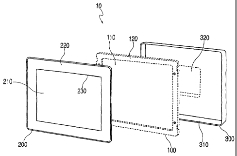
[0028] According to a preferred embodiment of the invention depicted in Fig.
1, the
electronic display 10 comprises an electronic display device 100, a cover 200
and an
enclosure 300 to which the display device 100 and the cover 200 are mounted.
(Some of the
components shown in the figures are exaggerated and shown somewhat
schematically for
purposes of explanation, and may not be to scale.)
[0029] The electronic display device 100 may be conventional and may comprise
any
device capable of generating and presenting images to a user, such as, for
example, an LCD
panel. An example of an electronic display device that may be used with the
invention is the
TFT LCD Model LTM170EI from Samsung Electronics Co., Ltd.
[0030] The electronic display device 100 (Fig. 1) includes an image-displaying
portion 110 on which images generated by the display device are presented to a
user. For
example, the image-displaying portion 110 of display device 100 may comprise
the display
7
CA 02497536 2005-03-02
WO 2004/023272 PCT/US2003/006434
area of an LCD panel. The side of the display device 100 on which images are
presented to a
user may be referred to as the front of the device.
[0031] The electronic display device 100 (Fig. 1) also includes another
portion 120
that is visible from the front of the display device 100, e.g., viewable by a
user looking at the
front of display device 100. The other portion 120 may comprise any component
part or parts
of display device 100 other than the image-displaying portion 110 that are
visible from the
front of display device 100, e.g., a frame or support for the display device
to support the
display device or for mounting the display device, or for other purposes. In
the embodiment
depicted in Fig. 1, the other portion 120 extends adjacent and surrounds the
image-displaying
portion 110. The other portion 120 maybe configured and located other than as
shown in
Fig. 1 depending upon the particular display device.
[0032] For example, where display device 100 (Fig. 1) is an LCD, the other
portion
120 is referred to as the LCD frame, that may serve a variety of functions,
such as, for
example, those described above. Where the display device 100 is an LCD, the
portion 120
may contain holes, as shown for example in Fig. 1, for mounting screws that
attach the
display device to the enclosure 300.
[0033] Referring to Fig. 1, the cover 200 includes at least a first portion
210 and a
second portion 220. A line 230 illustrates the demarcation of the first and
second portions
210, 220. However, the line 230 and the demarcation may not be visible,
depending upon
lighting conditions behind the cover 200. For example, with the cover 200
mounted to the
display device 100, and the display device 100 not displaying an image, e.g.,
having a
darkened image displaying portion 110, line 230 is not visible, and the cover
200 has a
uniform appearance as shown in Fig. 2. On the other hand, when the display
device 100 is
displaying an image, e.g., is projecting light in the form of an image, the
image will be visible
in portion 210 of cover 200, and line 230 will appear as a demarcation between
portions 210
8
CA 02497536 2005-03-02
WO 2004/023272 PCT/US2003/006434
and 220, with portion 220 appearing as a flush border to the image appearing
in cover portion
210. Fig. 5 depicts the display 10 displaying an image surrounded by a flush
border 220,
which is shown uncolored but in the preferred embodiment is darkened.
[0034] The first and second portions of the cover 200 are sized, and the cover
200 is
positioned adjacent to the front side of the electronic display device 100
with the first portion
210 of cover 200 positioned adjacent and at least coextensively with the image-
displaying
portion 110 of display device 100, and with the second portion 220 of cover
200 positioned
adjacent and at least coextensively with the portion 120 of display device
100. The size
relationship of the first and second portions 210, 220 of the cover 200 is
preferably identical
or substantially similar to the size relationship of the image-displaying
portion 110 and the
other portion 120 of the display device 100. In the embodiment depicted in
Fig. 1, the second
portion 220 of cover 200 surrounds the first portion 210.
[0035] The first portion 210 and second portion 220 of cover 200 each have
optical
properties selected such that, (a) when images are displayed on image-
displaying portion 110
of the electronic display device 100, the displayed images are suitably
transmitted through the
first portion 210 so as to be visible to a user, and may have a flush border
or frame 220, as
illustrated in Fig. 5 and, (b) when no images are displayed on the image-
displaying portion
110, the first portion 210 and second portion 220 of cover 200 present a
uniform appearance
such that they present a flush uniform front of the electronic display 100
without a bezel, as
illustrated in Fig. 2.
[0036] In a preferred embodiment of the invention, the optical properties of
second
portion 220 are selected so as to completely mask images of other portion 120
and any objects
and materials attached to portion 120, and thus prevent them from being
transmitted through
second portion 220 and being seen by a user. In this embodiment, cover 200 may
comprise
any suitable structure capable of transmitting light, such as, for example, a
glass or plastic
9
CA 02497536 2005-03-02
WO 2004/023272 PCT/US2003/006434
sheet, with portions 210 and 220 forming different regions of the sheet.
Portions 210 and 220
are provided with optical properties, e.g., tinting, or coloring, or
coating(s) such that (a)
images of other portion 120 of display device 100 and any objects and
materials attached to
portion 120 are not visible through second portion 220, and, (b) when images
are displayed
on image-displaying portion 110 of the electronic display device 100, the
displayed images
are transmitted through the first portion 210 so as to be visible to a user,
and, (c) when no
images are displayed on the image-displaying portion 110, the first portion
210 and second
portion 220 of cover 200 present a uniform appearance such that they appear to
be a single,
flush front or cover without a bezel.
[0037] The optical properties above may be imparted to second portion 220 of
cover
200 by, for example, applying a layer or coating of opaque material, e.g.,
paint or ink, to the
structure comprising cover 200 in the region of second portion 220. In the
preferred
embodiment, the color of the opaque material is selected so as to match the
appearance of
image-displaying portion 110 of display device 100 when no images are
displayed thereon.
This may be accomplished by, for example, obtaining the red, green, and blue
color values of
the image-displaying portion 110 of display device 100 when no images are
displayed
thereon, e.g., using a colorimeter, and selecting an opaque material having
the same color
values.
[0038] First portion 210 of cover 200 may be tinted or colored to impart
optical
properties as described above. In the preferred embodiment, tinting is
provided having
characteristics that are selected so that, when images are displayed on image-
displaying
portion 110 of the electronic display device 100, the displayed images are
suitably
transmitted, e.g., at 80% transmissivity, through the first portion 210 so as
to be visible to a
user, and yet, when no images are displayed on the image-displaying portion
110, the tint
provides an appearance of first portion 210 that matches the appearance of the
opaque
CA 02497536 2005-03-02
WO 2004/023272 PCT/US2003/006434
material applied to second portion 220, which together present the uniform
appearance
described herein.
[0039] In the preferred embodiment, the electronic display device 100 is an
LCD
panel, and the above described optical properties of the cover can be achieved
using an
acrylic plastic sheet as cover 200. (An acrylic sheet is sometimes referred to
as a lens,
although the sheet does not refringe light (e.g., focus or diverge light) as
would a lens.) The
acrylic sheet is preferably provided with an anti-glare coating (e.g., having
a gloss level of 44)
and a scratch-resistant coating. Such coatings are known in the art. The
second portion 220
of the plastic sheet includes a paint coating 220a having a color of standard
black as the
opaque material forming part of the second portion 220. The first portion 210
includes a tint
or coloring tint that does not noticeably alter colors of an image transmitted
through portion
210. For example, the first portion 210 may comprise a neutral gray tint
(e.g., smoked tint
#2064) and be about 80% transmissive.
[0040] The assembly depicted in Fig. 3 includes the cover 200, the display
device 100
and the enclosure 300. The second portion 220 of the cover is shown with a
coating or layer
of opaque material 220a. The assembly also includes an adhesive or bonding
agent 150
which attaches the cover 200 to the display device 100. The display device is
mounted to the
enclosure by screws passing through the rear of the enclosure and engaging
threaded holes
(see Fig. 1) in the frame 120 of the display device. Enclosure 300 comprises a
side wall 310
of sufficient height to accommodate at least the thickness of electronic
display device 100 and
the cover 200. In another embodiment depicted in Fig. 4, the cover is not
accommodated
within the enclosure but outside the enclosure, as discussed in more detail
below. A opening
320 at the rear of enclosure 300 maybe provided so as to allow access to the
rear of electronic
display device 100, where, for example, input and output connectors may be
located.
11
CA 02497536 2005-03-02
WO 2004/023272 PCT/US2003/006434
[0041] Although the first portion 210 and the second portion 220 are shown in
Fig. 1
and described above as separate regions of a single structure comprising cover
200, the
portions 210 and 220 may be separate pieces. For example, in an embodiment of
the
invention, first portion 210 and second portion 220 each may be distinct
structures attached in
any suitable manner together to form cover 200. In such an embodiment,
portions 210 and
220 may be shaped and attached together using known procedures, which may
include filling
any gaps between the two portions or otherwise providing a desired flush
appearance, such
that portions 210 and 220 present a bezel-less cover.
[0042] Cover 200 maybe mounted directly or indirectly (e.g., using a plastic
frame as
described below) to electronic display device 100 or enclosure 300 in any
suitable manner
that provides a secure attachment. It is preferred that a fastenless system be
used so that
fasteners are not visible from the cover 200. For example, cover 200 may be
attached to
display device 100, by an adhesive or thermal or acoustic bonding, so that
cover 200 and
display device 100 together form a sub-assembly. In the preferred embodiment,
VHBTM
Acrylic Foam Tape from the 3MTM Company is used. As shown in Fig. 3, the VHBTM
tape
150 may be used to mount cover 200 to electronic display device 100. As
assembled, the tape
is between the portion 120 of the display device 100 and portion 220 of cover
200 and
adheres the two. The tape may first be adhered to the portion 110 of the
display device and
then the portion of 220 of the cover 200 is adhered to the other side of the
tape, or vice versa.
[0043] The sub-assembly of the cover 200 adhered to display device 100 using
the
VHBTM tape, as described above, may be mounted to enclosure 300 by placing the
sub-
assembly into enclosure 300 (or vise versa) so that cover 200 is flush with
the raised edge 310
of enclosure 300 and then fixing the sub-assembly to enclosure 300 using
mounting screws
placed through holes in enclosure 300 and into the other portion 120 of
display device 100.
12
CA 02497536 2005-03-02
WO 2004/023272 PCT/US2003/006434
[0044] Alternatively, as discussed above, cover 200 may be sized and the sub-
assembly comprising cover 200 adhered to display device 100 may be mounted to
enclosure
300 such that cover 200 lies on top of the edge of side wall 310 of enclosure
300 flush with
the periphery thereof, as shown in Fig. 4. In this an embodiment, second
portion 220 of cover
200 covers side wall 310 of enclosure 300 as well as the other portion 120 of
display device
100. The sub-assembly maybe fixed to enclosure 300 in the same manner as
described above
using screws entering the electronic display 10 from the rear of the enclosure
300.
[0045] Where portion 220 has optical properties that completely mask whatever
is
behind it, then, when images are displayed on image-displaying portion 110 of
display device
100, portion 220 appears as an opaque, flush border or frame for portion 210.
Unlike
conventional displays, with a bezel that protrudes from the display screen,
portion 220 is part
of or appears to be part of the same structure comprising portion 210, and
does not protrude
from portion 210, but rather is flush or coplanar with portion 210.
[0046] Fig. 5 depicts an embodiment of the invention that includes a secondary
display device 400 that presents one or more images (represented by "Logo")
independently
of display device 100, which is referred to as the main display device in this
embodiment. In
one embodiment, the secondary display device 400 comprises an area 410 of the
second
portion 220 of cover 200 that is modified to form an image, such as, for
example, a corporate
logo, advertisement, licensed character, or personalized image or message,
etc., and a light
source 420 located behind this area 410 that transmits light through area 410
to present the
image.
[0047] Where the second portion 220 of cover 200 includes an opaque coating
220a
(Fig. 3), area 410 maybe formed by, for example, omitting opaque material in
the form of the
image. For instance, where paint is used as the layer of opaque material and
is applied to
second portion 220, any suitable masking or etching process may be employed.
13
CA 02497536 2005-03-02
WO 2004/023272 PCT/US2003/006434
[0048] The light source 420 may be any suitable source of light, such as an
LCD or an
LED. In the preferred embodiment, an LED assembly of the type commercially
available
from Global Lighting Technologies, Inc., as, e.g., the MicroLensTM LED, is
used. The
assembly is mounted behind the area 410 in any manner suitable to fix it
securely between the
cover 200 and the other portion 120 of the display device, and to direct light
to area 410. For
example, an adhesive or other bonding system, or fasteners, may be used to
attach the light
assembly 420 to the frame 120 of the display device 100. In the preferred
embodiment, the
light assembly 420 may be mounted by adhering it to the VHBTM tape placed on
other portion
120 of the display device 100 at the position behind area 410, as shown in
Fig. 6. Since the
VHBTM tape is compliant, the assembly 420 may be depressed into the VHBTM tape
so that,
when the cover 200 is adhered to the VHBTM tape and the other portion 120 of
display device
100, the VHBTM tape forms a seal around the assembly 420 that prevents light
from the LED
from leaking into the area behind the first portion 210 of cover 200 that may
otherwise be
visible to a user or an observer. If desired, a foam gasket may be placed
around the assembly
420 to ensure that no light leaks from the LED. The light source is powered by
known means
independently of the electronic display device 100 and can remain on even when
the display
device 100 is off or in an inactive "sleep" mode. For example, the power can
be derived from
the AC lines (as long as the display 10 remains connected to AC power), or by
battery power.
[0049] The portions of area 410 that do not form the image preferably have the
same
optical properties as portion 210. Thus, as shown in Fig. 7, when no images
are presented on
image-displaying portion 110 of display device 100, portions 210 and 220 of
cover 200
present a uniform appearance as described above, except for the image
presented by
secondary display 400.In another embodiment of the invention, shown in Fig. 8,
the image
presented by the secondary display device 400 comprises a plate or cover 430
mounted on the
exposed side of cover 200 overlying adjacent a light source (not shown), as
described above.
14
CA 02497536 2005-03-02
WO 2004/023272 PCT/US2003/006434
The image on plate or cover 430 maybe formed as described above. The plate or
cover 430
may also be mounted on the inside of cover 200 which then includes a light
transmitting
section in portion 220 overlaying the plate.
[00501 Another embodiment of the invention is shown in Figs. 9 and 10. An
electronic display 10 comprises an electronic display device 100, a cover 200,
and an
enclosure 300, as previously described above. The display device 100 fits into
a plastic frame
350 and is attached thereto by any suitable means, such as, for example,
screws entering the
sides of the frame 350 and into the sides of the other portion 120 of display
device 100.
Attached to the front of the display device 100, on other portion 120, is a
dust gasket 160.
Dust gasket 160 may be attached to other portion 120 by any suitable means,
such as, for
example, an adhesive. A light assembly 420, as described previously, fits into
a notch 380 at
a location within the frame 350 beneath the display device 100. The light
assembly 420 may
be attached to the frame 350 at notch 380 by any suitable means, such as, for
example, an
adhesive. Cover 200 is bonded to frame 350 in any suitable manner, such as,
for example,
using VHBTm tape 150, as described previously. A printed circuit board ("PCB")
360,
providing power and input and output connections, attaches to the back of
display device 100
in any suitable manner, such as, for example, fasteners, e.g., screws, or an
adhesive. A button
mounting board 370 mounts under the frame 350 in any suitable manner, such as,
for
example, using an adhesive, and provides buttons for controlling the display
device 100, e.g.,
on/off and brightness buttons. Buttons from the button mounting board 370
extend down
through holes 375 in a bottom sidewall 310 of enclosure 300 where they may be
accessed by
a user. The components above, i.e., frame 350, display device 100, dust gasket
160,
cover 200, light assembly 420, PCB board 360, and button mounting board 370
form a sub-
assembly that is then mounted to enclosure 300 in any suitable manner, such
as, for example,
screws entering through the back of enclosure 300 and into the back of frame
350.
CA 02497536 2005-03-02
WO 2004/023272 PCT/US2003/006434
[0051] While the invention has been described and illustrated in connection
with
preferred embodiments, many variations and modifications as will be evident to
those skilled
in this art may be made without departing from the spirit and scope of the
invention, and the
invention is thus not to be limited to the precise details of methodology or
construction set
forth above as such variations and modification are intended to be included
within the scope
of the invention.
16