Note: Descriptions are shown in the official language in which they were submitted.
CA 02498796 2005-03-O1
-1-
Insulated Container and Cushion Assembly
Field of the Invention
This application relates to the field of insulated container assemblies.
Background of the Invention
Insulated containers may sometimes be used by persons who wish to attend a
sporting
event, or who wish to enjoy an outside meal such as a picnic. The insulated
container may be
used to hold beverages or other refreshments that one may wish to keep cool or
cold such as ice
cream, carbonated drinks, juices or beer, or beverages or foods that one may
which to keep warm
or hot such as hot chocolate, tea, soup, appetizers, hot dogs, hamburgers, and
so on.
When attending a sporting event in the Autumn, for example, one may wish to
have a
supply of hot drinks, or hot foods, and a cushion upon which to sit that may
be warmer than cold
aluminum bleachers. Alternatively, one may wish to have a blanket that may be
spread on the
ground at a picnic, or that may be used to stay warm on a chilly day.
Summary of the Invention
In an aspect of the invention, there is a soft sided insulated container
assembly. It
includes an insulated wall structure having a first, insulated, chamber
defined therein and a first
closure member operable to govern access to the chamber. An auxiliary wall
structure is
releasably attached thereto. The auxiliary wall structure has a second chamber
defined therein,
and has a second closure member governing access to the second chamber. In
addition, there is a
pliable resilient member. The pliable resilient member is movable between a
first, folded
position within the auxiliary wall structure, and a second, unfolded position.
In the second,
unfolded position the pliable resilient member has a plan form extent that is
more than 10 times
as great as when it is in the folded position. The auxiliary wall structure
has a profile of a size
comparable to, or smaller than, the insulated wall structure.
In another feature, in the folded position, the pliable resilient member has a
number of
plies that is in the range of 10 to 30. The number may be in the range 12 to
20.
In another feature, the soft-sided insulated container has an insulated wall
structure. The
CA 02498796 2005-03-O1
-2-
insulated wall structure is movable between an expanded position and a
collapsed position, and
has securement fittings operable to secure said insulated wall structure in
said collapsed position.
In a further feature, the insulated wall structure has an externally
accessible beverage
container accommodation. The soft-sided insulated container with the auxiliary
wall structure is
a cushion. The cushion employs a resilient pliable member as a stuffing. The
resilient pliable
member, is folded and located within the auxiliary wall structure, the
resilient pliable member
has at least ten folded plies. In another feature, the soft-sided insulated
container includes a
sound reproduction device.
In another aspect of the investion, there is a soft-sided insulated container
assembly, that
includes a six-sided thermally insulated container, and a second soft-sided
enclosure detachably
mounted to the thermally insulated container. The thermally insulated
container has a height and
a width. The second, soft-sided container has a large side of comparable
extent to the height and
width of the thermally insulated container. The second, soft-sided container
is detachable from
the thermally insulated container and, when so detached, is operable as a
cushion. The second,
soft-sided container has a closure member operable to govern access thereto
and the second, soft-
sided container has a cushioning material stored therein. The cushioning
material is unfoldable,
and, in an unfolded position, the cushioning material is operable as a
blanket.
In a further feature, the soft-sided insulated container assembly has a
beverage holder
socket mounted to the thermally insulated container, the socket being
externally accessible. In
another feature, the soft-sided insulated container assembly has a sound
reproduction apparatus.
In a further feature, the second soft-sided container and the thermally
insulated container, when
attached, are connected in a back-to-back manner. The second soft sided
container and the
thermally insulated container, when attached, are connected across mutual
upper margins of
opposed sides, and in another region distant from those upper margins. When
mounted to the
thermally insulated container, the second soft-sided container has a profile
that lies one of (a)
flush with; and (b) shy of, a corresponding profile of the thermally insulated
container. The
thermally insulated container is movable between an extended position and a
collapsible
position. In a further feature, the thermally insulated container has
releasable securements that
are operable to retain the thermally insulated container in the collapsed
position.
In still another feature, the thermally insulated container is movable to a
collapsed
position, and is securable in the collapsed position. When attached, the
second soft-sided
container is mounted in a back-to back fashion on the thermally insulated
container. When
CA 02498796 2005-03-O1
-3-
attached, the second soft-sided container has a profile that is one of (a)
flush with, and (b) shy of,
a corresponding profile of the thermally insulated container, in both width
and height. The
cushioning material is a blanket that may be removed entirely from the second
soft-sided
container. The thermally insulated container has at least one beverage
receptacle mounted
thereto. The thermally insulated container has a first lifting member and the
second container
has a second lifting member. The soft-sided container assembly has at least
one of (a) a CD
player; and (b) a radio, mounted thereto.
Brief Description of the Illustrations
These aspects and other features of the invention may be understood with the
aid of the
following illustrations of a number of exemplary, and non-limiting,
embodiments ofthe principles of
the invention in which:
Figure la is a perspective view from in front, one side and above of an
embodiment of
container assembly;
Figure 1b is a perspective view from behind to the rear and above of the
container assembly
of Figure la;
Figure lc is a front view of the container assembly of Figure la;
Figure 1d is a rear view of the container assembly of Figure la;
Figure 1e is a right hand side view of the container assembly of Figure la;
Figure if is a left hand side view of the container assembly of Figure la;
Figure 1g is a top view of the container assembly of Figure la;
Figure 1h is a bottom view of the container assembly of Figure la;
Figure 2a is a perspective view from in ftont, above and to the right hand
side of the
container assembly of Figure la in a collapsed position;
Figure 2b is a perspective view from behind, above and to one side ofthe
container assembly
of Figure 2a;
Figure 2c is a front view of the container assembly of Figure 2a;
Figure 2d is a right hand side view of the container assembly of Figure 2a;
Figure 2e is a left hand side view of the container assembly of Figure 2a;
Figure 2f is a rear view of the container assembly of Figure 2a;
Figure 2g is a top view of the container assembly of Figure 2a;
Figure 2h is a bottom view of the container assembly of Figure 2a;
Figure 3a is a perspective view from in front, above and to the right hand
side of a portion of
the container assembly of Figure la;
Figure 3b is a perspective view from above, behind and to the left hand side
of the container
CA 02498796 2005-03-O1
-4-
assembly portion of Figure 3a;
Figure 3c shows the container assembly portion of Figure 3a in an open
condition;
Figure 3d shows a cross-sectional view of the container assembly portion of
Figure 3a;
Figure 4a is a perspective view of another portion of the container assembly
of Figure la;
Figure 4b is an opposite diagonal view of the container assembly portion of
Figure 4a;
Figure 5a is a perspective view of the container assembly of Figure 1 a with a
foldable web
element removed therefrom;
Figure Sb shows the container assembly of Figure la in a fully deployed
condition; and
Figure 5c shows an alternate container assembly to that of Figure la having a
sound
production apparatus.
Detailed Description
The description that follows, and the embodiments described therein, are
provided by
way of illustration of an example, or examples, of particular embodiments of
the principles of the
present invention. These examples are provided for the purposes of
explanation, and not of
limitation, of those principles and of the invention. In the description, like
parts are marked
throughout the specification and the drawings with the same respective
reference numerals. The
drawings are not necessarily to scale and in some instances proportions may
have been
exaggerated in order more clearly to depict certain features of the invention.
For the purposes of this description, various panels of the insulated
containers herein
described are arbitrarily designated as the front and rear sides, faces, or
portions. Similarly, the
closure member, or opening of the insulated container is arbitrarily
designated as being at the
top, and the base panel is designated as being at the bottom. These terms are
arbitrary, and are
chosen for convenience as being those that may be used when the container
assembly described
is in normal use. However, a panel that may be the front or back in one
context, may be the side,
or top or bottom in another, and a panel that may be the bottom or top, may be
some other panel
in a different context. It should also be understood that, within the normal
range of temperatures
to which human food and human touch is accustomed, although the term cooler,
or cooler
container, or cooler bag, may be used, such insulated structures may generally
also be used to
keep food, beverages, or other objects either warm or hot as well as cool,
cold, or frozen.
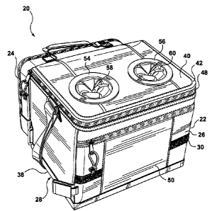
In the illustrations, an insulated container assembly is indicated generally
as 20.
Insulated container assembly 20 may include a first portion 22 and a second
portion 24. The first
and second portions may be releasably attached.
CA 02498796 2005-03-O1
-5-
First portion, 22 may be an insulated container assembly that includes an
insulated wall
assembly 26. Wall assembly 26 may include a base portion identified as a
bottom panel 28, and
an upstanding sidewall 30, which may include a front wall panel 32, a rear
wall panel 34, a left
hand side panel 36 and a right hand side panel 38. Wall assembly 26 may also
include a top
panel 40. Top panel 40 may be movably mounted relative to sidewall 30, and may
be releasably
secured thereto at a closure 42 at which top panel 40 mates releasably with
the upper rim 44 of
sidewall 30. Top panel 40 may be hingedly attached to sidewall 30, as
indicated at 46. Closure
42 may be a releasable tracked closure, such as may be in the nature of a
zipper 48 extending
about three sides of rim 44. Front wall panel 32 may include a pouch or
pocket, or auxiliary
compartment 50, to which access may be governed by another closure member 52.
Auxiliary
compartment 50 may be used for such things as knives and forks, napkins,
condiments, or such
other objects as may be desired.
First portion 22 may be provided with accommodations 54, 56 such as may have
the form
of a generally round cylindrical socket 58, 60, having a round base 62 and
cylindrical wall 64
depending from a collar 66 and backing ring 68 that are fastened together to
sandwich the
surrounding region of top panel 40. Accommodations 54, 56 may be externally
accessible such
that a beverage container may be placed therein, possibly in a partially
protruding manner,
without having to open first portion 22 more generally, that is,
accommodations 54, 56 each have
an opening that faces externally to first portion 22 more generally. Base 62
and cylindrical wall
64 may have an inner skin 70, and outer skin 72 and a layer of insulation 74.
The insulated wall
structure of first portion 22 may have a generally six-sided box shape, and
may tend to define an
insulated internal space, chamber, or compartment 80. Sockets 58, 60 may be
soft sided such
that, when those sockets are not occupied, they may be collapsed and pushed
out of the way of
other objects that may be placed within compartment 80 of first portion 22
more generally, or
when first portion 22 is moved to a collapsed or storage position. Sockets 58,
60 may have a
diameter in the range of about 3 inches (+/-'/Z inch) and may have a depth of
about 4 inches (+/-
3/4 inches) and may be of a size to accommodate a 12 oz. beverage can.
Each of bottom panel 28, front wall panel 32, rear wall panel 34, left hand
wall panel 36,
right hand side wall panel 38, and top panel 40 may include an outer membrane
or covering,
such as may be a fabric or plastic sheet, and such as may be represented by
woven polyester or
nylon fabric or other material, and may be identified as outer layer 82; an
inner layer, which may
be a nylon or polypropylene sheet, and which may be of a reflective coated
plastic, such as the
material sold under the trade mark Thermoflect (T.M.), and which may be
identified as inner
CA 02498796 2005-03-O1
-6-
layer 84; and an intermediate layer such as may be a layer of thermal
insulation 86, which may,
for example, be an open or closed cell foam. In this specification, an
insulated panel may be
understood to be one in which a thermally insulative material, such as a layer
of foam or felt, or
other insulative medium has been incorporated, over and above whatever layer
of webbing or
fabric might otherwise define a soft-sided wall surface that is not identified
as being insulative.
That is to say, a layer of canvas or other webbing, alone, may not generally
be considered to be
an insulated wall, absent some other additional insulative feature.
First portion 22 may be movable between an expanded, or deployed condition as
shown
in Figure la, to a collapsed position as shown in Figure 2a. In the collapsed
position, bottom
panel 28 is forced upwardly, left and right side wall panels 36 and 38 are
moved inwardly, and
the lip of top panel 40 is drawn down over front wall panel 30 and secured to
hook-and-eye
fastener strips 88. Further securement is provide by side wall securement
fittings 90, 92. First
portion 22 may also have a lifting fitting, such as ring 94, and a lifting
member, such as a
carrying strap, 96.
Second portion 24 may include a wall structure 100 having a back wall 102, an
outstanding peripheral sidewall 104, and a front face wall 106. Each of these
may be a flexible
fabric panel. Back wall 102 and front face wall 106 may have substantially the
same plan form.
Outstanding peripheral wall 104 may include bottom, top, left and right hand
portions 110,112,
114, and 116, that form a generally rectangular shape. A peripheral portion of
front face wall
106 may be connected to outstanding peripheral front face wall 104 by means of
a closure 122,
such that a portion or region 118 of wall structure 100 may open to provide
access to an enclosed
space, indicated generally as 120,°into which an object may be placed.
That object may be a
foldable covering member 130, such as may be a folded ground sheet, or blanket
132. Blanket
132 may be made of a wool or synthetic wool, or thick expanded polyester cloth
material, such
as may tend to have greater thickness than, for example, a linen sheet.
Furthermore, blanket 132,
when folded, may have sufficient resiliency to function as a cushion when
enclosed in second
portion 24.
Second portion 24 may be detachably secured to first portion 22. For example,
a
detachable tracked fastener 134 may have halves that run along the upper edge
of back wall 102
of wall structure 100, and along the upper margin of rear wall panel 34,
respectively, thereby
connecting them together when the tracked fastener is engaged. In addition, a
second
securement fitting, or fittings 136 may be mounted to connect regions of back
wall 102 and rear
wall panel 34, and may serve to encourage second portion 24 to stay in
position relative to first
CA 02498796 2005-03-O1
-7-
portion 22 in a substantially planar, or back-to-back orientation. Securement
fittings 136 may be
engageable hook-and-eye fabric strips such as sold under the trademark
"Velcro". Second
portion 24 may also include a carrying member, be it a handle 140, as may be
mounted along top
portion 112 of wall structure 100.
Second portion 24 may have a footprint, which is to say, the projected profile
of back
wall 102, for example, that falls substantially within a range that is less
than 20 % greater in
either height, h, or width, w, than the corresponding area of rear wall panel
34 of first portion 22,
in one or both of height and width, and which may be more than 75 % of the
height, or width, or
both, of rear wall panel 34 of first portion 22. In one embodiment, second
portion 24 may be of
substantially the same width as rear wall panel 34. The height of second
portion 24 may be
substantially the same as, or less than, the height of first portion 22. The
height of second
portion 24 may be less than the height of first portion 22 by an amount that
is greater than, or
substantially equal to, the thickness of handle 140, such that the extent that
handle 140 may
protrude upward may be such as to lie below, or substantially flush with, top
wall panel 40. The
lower margin of second portion 24 may be mounted (when second portion 24 is
attached to first
portion 22) in a position that is substantially flush with the bottom margin
of rear wall panel 34
of first portion 22. Further, second portion 24 may have substantially the
same width as a single
seat of a bleacher. For example, the width of second portion 24 may be in the
range of greater
than 10 inches, to about 20 inches, and may be in the range of about 12 to 16
inches. The aspect
ratio of the short side to the long side may be in the range of 3/5 to 1:1,
and may be in the range
of about'/4, +/- 10 %.
In an unfolded condition, blanket 132 may have an area that is in the range of
15 to 40
times the nominal area of the footprint of second portion 24 when used as a
cushion. In one
embodiment it may be about 25 times as large, +/- 20 %. Alternatively, in a
folded condition,
blanket 132 may be folded to give a number of plies that is in the range of 10
to 30, and in one
embodiment may be about 16 plies (+/- 4).
In an alternate embodiment, shown in Figure 5c, an insulated container
assembly 150
may be substantially the same as insulated container assembly 20, but, in
addition, may include a
portable sound projecting system 152, such as may include a radio 154 or CD
player 156 or both.
Although the embodiments illustrated and described above are preferred, the
principles of
the present invention are not limited to these specific examples, which are
given by way of
illustration. Since changes in or additions to the above-described
embodiments, or both, may be
CA 02498796 2005-03-O1
_8_
made without departing from the nature, spirit or scope of the invention, the
invention is not to
be limited to those details.