Language selection

Search

Patent 2498927 Summary

Third-party information liability

Some of the information on this Web page has been provided by external sources. The Government of Canada is not responsible for the accuracy, reliability or currency of the information supplied by external sources. Users wishing to rely upon this information should consult directly with the source of the information. Content provided by external sources is not subject to official languages, privacy and accessibility requirements.

Claims and Abstract availability

Any discrepancies in the text and image of the Claims and Abstract are due to differing posting times. Text of the Claims and Abstract are posted:

  • At the time the application is open to public inspection;
  • At the time of issue of the patent (grant).
(12) Patent: (11) CA 2498927
(54) English Title: METHOD AND SYSTEM FOR CHECKING TRACK INTEGRITY
(54) French Title: PROCEDE ET SYSTEME DE VERIFICATION DE L'INTEGRITE D'UNE VOIE
Status: Expired
Bibliographic Data
(51) International Patent Classification (IPC):
  • B61L 3/00 (2006.01)
  • B61L 23/04 (2006.01)
(72) Inventors :
  • KANE, MARK EDWARD (United States of America)
  • SHOCKLEY, JAMES FRANCIS (United States of America)
  • HICKENLOOPER, HARRISON THOMAS (United States of America)
(73) Owners :
  • SIEMENS INDUSTRY, INC. (United States of America)
(71) Applicants :
  • QUANTUM ENGINEERING, INC. (United States of America)
(74) Agent: SMART & BIGGAR LP
(74) Associate agent:
(45) Issued: 2016-06-14
(86) PCT Filing Date: 2003-10-10
(87) Open to Public Inspection: 2004-04-22
Examination requested: 2006-06-21
Availability of licence: N/A
(25) Language of filing: English

Patent Cooperation Treaty (PCT): Yes
(86) PCT Filing Number: PCT/US2003/032424
(87) International Publication Number: WO2004/033267
(85) National Entry: 2005-03-14

(30) Application Priority Data:
Application No. Country/Territory Date
10/267,962 United States of America 2002-10-10

Abstracts

English Abstract


A train control system includes a control module that determines a position of
a train using a positioning system and consults a database to determine when
the train is approaching a portion of track monitored by a track circuit. When
the train is near a track circuit, but while the train is still far enough
away from the track circuit such that the train can be stopped before reaching
the portion of track monitored by the track circuit, the train transmits an
interrogation message to a transceiver associated with the track circuit. When
the track circuit receives the interrogation message, a test is initiated. The
test results are transmitted back to the train. The train takes corrective
action if the track circuit fails to respond or indicates a problem.


French Abstract

L'invention porte sur un système de contrôle des trains qui comprend un module de commande qui détermine la position d'un train à l'aide d'un système de positionnement et consulte une base de données afin de déterminer si le train approche d'une partie de voie surveillée par un circuit. Lorsque le train approche du circuit, tout en étant toujours assez loin de celui-ci de façon à pouvoir stopper avant d'atteindre la partie de la voie surveillée par ledit circuit, le train envoie un message d'interrogation à un émetteur-récepteur associé au circuit. A la réception du message d'interrogation par le circuit, un test est déclenché. Les résultats du test sont retransmis au train qui entreprend alors une action corrective dans le cas où le circuit ne répond pas ou présente ou un problème.

Claims

Note: Claims are shown in the official language in which they were submitted.


CLAIMS:
1. A system for controlling a train, the system comprising:
a control unit;
a warning device in communication with the control unit;
a brake interface unit, the brake interface unit being in communication with
the
control unit and a train brake, the brake interface unit being operable to
activate the train
brake under control of the control unit; and
a transceiver, the transceiver being located on the train and being in
communication
with the control unit; wherein the control unit is configured to perform the
steps of
transmitting an interrogation message to a track circuit transceiver
associated
with a track circuit;
listening for a response from the track circuit transceiver, the response
including an indication as to a condition of a section of track monitored by
the track circuit;
and
activating the warning device if the response indicates that it is not safe
for the
train to proceed.
2. The system of claim 1, where the control unit is further configured to
perform the
steps of:
determining whether activating the train brake is necessary to prevent the
train from
reaching the section of track monitored by the track circuit; and
activating the train brake via the brake interface based on a result of the
determining
step .
3. The system of claim 1, wherein the track circuit is a broken rail detection
circuit.
4. The system of claim 1, wherein the track circuit is a circuit that detects
the presence
of a train.
5. The system of claim 1, wherein the track circuit is an avalanche detection
circuit.
- 13 -

6. The system of claim 1, wherein the track circuit is a bridge alignment
detection
circuit.
7. The system of claim 1, wherein the response includes an identification
number of
the track circuit and wherein the control unit is further configured to
perform the step of
confirming that identification number received in the response corresponds to
the track circuit
to which the interrogation message was directed.
8. The system of claim 1, wherein the interrogation message includes an
identification
number of a track circuit for which the interrogation message is intended.
9. The system of claim 1, further comprising:
a positioning system, the positioning system being in communications with the
control unit and being configured to provide position information to the
control unit; and
a database, the database including a plurality of locations for a plurality of
track
circuits;
wherein the control unit is further configured to perform the steps of
identifying a track circuit in the database which is a next track circuit
which
the train will pass based on information from the positioning system; and
obtaining an identification number from the database associated with the track

circuit identified in the identifying step.
10. The system of claim 9, wherein the control unit is configured to transmit
the
interrogation message when a distance between the train's location and the
track circuit
identified in the identifying step is below a threshold.
11. The system of claim 10, wherein the threshold is a predetermined number
based at
least in part on an expected worst case distance required to stop the train.
12. The system of claim 10, wherein the threshold is determined dynamically
based at
least in part upon the current speed of the train.
13. The system of claim 12, wherein the threshold is further based on a weight
of the
train
- 14 -

14. The system of claim 12, wherein the database further includes a grade of a
track
between the train and the track circuit and the threshold is further based on
the grade of the
track between the train and the track circuit.
15. The system of claim 14, wherein the threshold is further based on
distribution of
weight in the train.
16. The system of claim 1, wherein the control unit is further configured to
activate
the warning device when a response with a correct configuration is not
received
17. The system of claim 16, wherein the control unit is further configured to
perform
the step of preventing the train from continuing until an acknowledgment of
the activated
warning device has been received.
18. The system of claim 1, where in the warning device is a display.
19. The system of claim 1, wherein the warning device is a horn.
20. A method for providing information as to a condition of a train track,
comprising
the steps of:
transmitting an interrogation message to a track circuit transceiver
associated with a
track circuit near the train;
listening for a response from the track circuit transceiver, the response
including an
indication as to a condition of a section of track monitored by the track
circuit;
reporting the response to a person operating the train;
allowing the train to continue if a response indicating that it is safe for
the train to
proceed; and
activating the train brake if necessary to stop the train before reaching the
section of
track monitored by the track circuit otherwise.
21. The method of claim 20, wherein the track circuit is a broken rail
detection circuit.
22. The method of claim 20, wherein the track circuit is a circuit that
detects the
presence of a train.
23. The method of claim 20, wherein the track circuit is an avalanche
detection
circuit.
- 15 -

24. The method of claim 20, wherein the track circuit is a bridge alignment
detection
circuit.
25. The method of claim 20, wherein the response includes an identification
number
of the track circuit and the method further comprises the step of confirming
that identification
number received in the response corresponds to the track circuit to which the
interrogation
message was directed.
26. The method of claim 20, wherein the interrogation message includes an
identification number of the track circuit for which the interrogation message
is intended.
27. The method of claim 20, further comprising the steps of: identifying a
track circuit
in a database which is a next track circuit which the train will pass based on
information from
a positioning system located on the train; and obtaining an identification
number associated
with the track circuit identified in the identifying step from the database.
28. The method of claim 27, wherein the interrogation message is transmitted
when a
distance between the train's location and the track circuit identified in the
identifying step is
below a threshold.
29. The method of claim 28, wherein the threshold is a predetermined number
based
at least in part on an expected worst case distance required to stop the
train.
30. The method of claim 28, wherein the threshold is determined dynamically
based
at least in part upon the current speed of the train.
31. The method of claim 30, wherein the threshold is further based on a weight
of the
train.
32. The method of claim 30, wherein the database further includes a grade of a
track
between the train and the section of track monitored by the track circuit and
the threshold is
further based on a grade of the track between the train and the section of
track monitored by
the track circuit.
33. The method of claim 32, wherein the threshold is further based on
distribution of
weight in the train.
34. The method of claim 20, further comprising the step of activating a
warning
device when a response with a correct configuration is not received
35. The method of claim 34, further comprising the step of preventing the
train from
continuing until an acknowledgment of the activated warning device has been
received
-16-

36. A system for controlling a train, the system comprising:
a control unit,
a warning device connected to the control unit and comprising an input unit
for
inputting an acknowledgment signal;
a brake interface unit, the brake interface unit being in communication with
the
control unit and connected to a train brake, the brake interface unit being
operable to
activate the train brake under control of the control unit; and
a transceiver, the transceiver being located on the train and being in
communication
with the control unit; and
a speed sensor in communication with the control unit,
wherein the control unit is configured to perform the steps of
transmitting an interrogation message to a track circuit transceiver
associated
with a track circuit near the train,
listening for a response from the track circuit transceiver, the response
including an indication as to a condition of a section of track monitored by
the track circuit;
if no response is received or if a response with an indication that it is not
safe
to proceed is received,
activating the warning device to provide a warning;
stopping the train by activating the brakes via the brake interface unit
if an acknowledgment of the warning is not received via the input unit or the
train is not
slowed to a given speed within a given period of time; and
if an acknowledgment of the warning is received via the input unit and
the train is slowed to the given speed within the given period of time,
ensuring that the given speed is maintained until the section of track
has been passed.
37. The system of claim 36, wherein the warning device is a horn.
38. The system of claim 36, wherein the warning device is a display.
39. The system of claim 37, comprising a communication unit connected to the
control unit, the control unit being further configured to perform the step of
preventing the
- 17 -

train continuing until permission is received from a dispatcher via the
communication unit if
the train has been stopped by the control unit in the stopping step.
40. The system of claim 36, wherein the given period of time is based on a
worst-
case assumption that the train is traveling at a maximum speed and weighs a
maximum
amount.
41. The system of claim 36, further comprising a positioning system in
communication with the control unit and located on the train, wherein the
given period of
time is based on an actual speed of the train based on information reported by
the
positioning system and a weight of the train.
42. The system of claim 36, further comprising a track database in
communication
with the control unit, wherein the given period of time is further based on a
grade of a section
of track between the train and the track circuit.
43. The system of claim 36, wherein the track circuit is a broken rail
detection circuit.
44. The system of claim 36, wherein the track circuit is a circuit that
detects the
presence of a train.
45. The system of claim 36, wherein the track circuit is an avalanche
detection circuit.
46. The system of claim 36, wherein the track circuit is a bridge alignment
detection
circuit.
47. The system of claim 36, wherein the response includes an identification
number
of the track circuit and wherein the control unit is further configured to
perform the step of
confirming that identification number received in the response corresponds to
the track
circuit to which the interrogation message was directed.
48. The system of claim 36, wherein the interrogation message includes an
identification number of a track circuit for which the interrogation message
is intended
49. A method for controlling a train comprising the steps of
transmitting an interrogation message to a track circuit transceiver
associated with a
track circuit near the train, the track circuit being configured to monitor a
section of track,
listening for a response from the track circuit, the response including an
indication as
to a condition of a section of track monitored by the track circuit,
allowing the train to continue if a response indicating that it is safe for
the train to
proceed is received;
- 18 -

if a response with a correct configuration is not received or if the response
indicates
that it is not safe for the train to proceed,
reducing a speed of the train;
activating a warning device to provide a warning; stopping the train if an
acknowledgment of the warning is not received within a given period of time or
the train is
not reduced to a given speed; and
if an acknowledgment of the warning is received and the train is reduced to
the given speed within the given period of time,
ensuring that the given speed is maintained until the section of track
monitored by the track circuit has been passed.
50. The method of claim 49, wherein the given period of time is based on a
worst-
case assumption that the train is traveling at a maximum speed and weighs a
maximum
amount.
51. The method of claim 49, wherein the given period of time is based on an
actual
speed of the train based on information reported by a positioning system and a
weight of the
train.
52. The method of claim 51, wherein the given period of time is further based
on a
grade of a section of track between the train and the track circuit.
53. The method of claim 49, wherein the track circuit is a broken rail
detection circuit.
54. The method of claim 49, wherein the track circuit is a circuit that
detects the
presence of a train.
55. The method of claim 49, wherein the track circuit is an avalanche
detection
circuit.
56. The method of claim 49, wherein the track circuit is a bridge alignment
detection
circuit.
57. The method of claim 49, wherein the response includes an identification
number
of the track circuit and wherein the control unit is further configured to
perform the step of
confirming that identification number received in the response corresponds to
the track
circuit to which the interrogation message was directed.
58. The method of claim 49, wherein the interrogation message includes an
identification number of a track circuit for which the interrogation message
is intended
- 19 -

59. The system of claim 1, wherein the track circuit is in a low power state
where no
train is nearby.
60. The system of claim 1, wherein the track circuit is in an off state when
no train is
nearby.
61. The system of claim 1, wherein the track circuit transceiver is in a low
power state
when no train is nearby.
62. The method of claim 20, wherein the track circuit is in a low power state
where no
train is nearby.
63. The method of claim 20, wherein the track circuit is in an off state when
no train is
nearby.
64. The method of claim 20, wherein the track circuit transceiver is in a low
power
state when no train is nearby.
65. The system of claim 36, wherein the track circuit is in a low power state
where no
train is nearby.
66. The system of claim 36, wherein the track circuit is in an off state where
no train is
nearby.
67. The system of claim 36, wherein the track circuit transceiver is in a low
power
state when no train is nearby.
68. The method of claim 49, wherein the track circuit is in a low power state
where no
train is nearby.
69. The method of claim 49, wherein the track circuit is in an off state when
no train is
nearby.
70. The method of claim 49, wherein the track circuit transceiver is in a low
power
state when no train is nearby.
71. A system for controlling a train, the system comprising: a control unit; a
warning
device in communication with the control unit and comprising an input unit for
inputting an
acknowledgment signal; a brake interface unit, the brake interface unit being
in
communication with the control unit and a train brake, the brake interface
unit being operable
to activate the train brake under control of the control unit; and a
transceiver, the transceiver
being located on the train and being in communication with the control unit;
wherein the
control unit is configured to perform the steps of transmitting an
interrogation message to a
track circuit transceiver associated with a track circuit; listening for a
response from the track
- 20 -

circuit transceiver, the response including an indication as to a condition of
a section of track
monitored by the track circuit; activating the warning device to provide a
warning to an
operator if the response indicates that it is not safe for the train to
proceed; and activating
the train's brake via the brake interface unit if an operator of the train
fails to acknowledge
the warning via the input unit or fails to reduce the speed of the train to a
given speed within
a given period of time after the warning.
72. The system of claim 71, wherein the track circuit is a broken rail
detection circuit
73. The system of claim 71, wherein the track circuit is a circuit that
detects the
presence of a train.
74. The system of claim 71, wherein the track circuit is an avalanche
detection circuit.
75. The system of claim 71, wherein the track circuit is a bridge alignment
detection
circuit.
76. The system of claim 71, wherein the response includes an identifier of the
track
circuit and wherein the control unit is further configured to perform the step
of confirming that
the identifier received in the response corresponds to the track circuit to
which the
interrogation message was directed.
77. The system of claim 71, wherein the interrogation message includes an
identifier
of a track circuit for which the interrogation message is intended.
78. The system of claim 71, further comprising: a positioning system, the
positioning
system being in communications with the control unit and being configured to
provide
position information to the control unit; and a database, the database
including a plurality of
locations for a plurality of track circuits; wherein the control unit is
further configured to
perform the steps of identifying a track circuit in the database which is a
next track circuit
which the train will pass based on information from the positioning system,
and obtaining an
identifier from the database associated with the track circuit identified in
the identifying step
and including the identifier in the interrogation message.
79. The system of claim 78, wherein the control unit is configured to transmit
the
interrogation message when a distance between the train's location and the
track circuit
identified in the identifying step is below a threshold.
80. The system of claim 79, wherein the threshold is a predetermined number
based
at least in part on an expected worst case distance required to stop the train
- 21 -

81. The system of claim 79, wherein the threshold is determined dynamically
based
at least in part upon the current speed of the train.
82. The system of claim 81, wherein the threshold is further based on a weight
of the
train
83. The system of claim 81, wherein the database further includes a grade of a
track
between the train and the track circuit and the threshold is further based on
the grade of the
track between the train and the track circuit.
84. The system of claim 83, wherein the threshold is further based on
distribution of
weight in the train.
85. The system of claim 71, wherein the control unit is further configured to
activate
the warning device when a response with a correct configuration is not
received.
86. The system of claim 85, wherein the control unit is further configured to
perform
the step of preventing the train from continuing until an acknowledgment of
the activated
warning device has been received.
87. The system of claim 71, where in the warning device is a display.
88. The system of claim 71, wherein the warning device is a horn.
89. A method for controlling a train comprising the steps of transmitting an
interrogation message to a track circuit transceiver associated with a track
circuit near the
train; listening for a response from the track circuit transceiver, the
response including an
indication as to a condition of a section of track monitored by the track
circuit; activating a
warning device to provide a warning to the operator if the response indicates
that it is not
safe to proceed or no response is received; and activating the train's brake
to stop the train if
an operator of the train fails to acknowledge the warning or fails to reduce
the speed of the
train to a given speed within a given time period
90. The method of claim 89, further comprising the steps of: allowing the
train to
continue if a response indicating that it is safe for the train to proceed is
received; and
activating the train brake if necessary to stop the train before reaching the
section of track
monitored by the track circuit otherwise
91. The method of claim 89, wherein the track circuit is a broken rail
detection circuit
- 22 -

92. The method of claim 89, wherein the track circuit is a circuit that
detects the
presence of a train.
93. The method of claim 89, wherein the track circuit is an avalanche
detection
circuit.
94. The method of claim 89, wherein the track circuit is a bridge alignment
detection
circuit.
95. The method of claim 89, wherein the response includes an identifier of the
track
circuit and the method further comprises the step of confirming that the
identifier received in
the response corresponds to the track circuit to which the interrogation
message was
directed.
96. The method of claim 89, wherein the interrogation message includes an
identifier
of the track circuit for which the interrogation message is intended.
97. The method of claim 89, further comprising the steps of: identifying a
track circuit
in a database which is a next track circuit which the train will pass based on
information from
a positioning system located on the train; and obtaining an identifier
associated with the
track circuit identified in the identifying step from the database.
98. The method of claim 97, wherein the interrogation message is transmitted
when a
distance between the train's location and the track circuit identified in the
identifying step is
below a threshold.
99. The method of claim 98, wherein the threshold is a predetermined number
based
at least in part on an expected worst case distance required to stop the
train.
100. The method of claim 98, wherein the threshold is determined dynamically
based
at least in part upon the current speed of the train.
101. The method of claim 100, wherein the threshold is further based on a
weight of
the train.
102. The method of claim 100, wherein the database further includes a grade of
a
track between the train and the section of track monitored by the track
circuit and the
threshold is further based on a grade of the track between the train and the
section of track
monitored by the track circuit.
- 23 -

103. The method of claim 102, wherein the threshold is further based on
distribution
of weight in the train.
104. The method of claim 89, further comprising the step of activating a
warning
device when a response with a correct configuration is not received.
105. The method of claim 104, further comprising the step of preventing the
train
from continuing until an acknowledgment of the activated warning device has
been received.
106. A system for controlling a train, the system comprising: a control unit;
a warning
device connected to the control unit and comprising an input unit for
inputting an
acknowledgment signal; a brake interface unit, the brake interface unit being
in
communication with the control unit and connected to a train brake, the brake
interface unit
being operable to activate the train brake under control of the control unit;
and a transceiver,
the transceiver being located on the train and being in communication with the
control unit;
wherein the control unit is configured to perform the steps of transmitting an
interrogation
message to a track circuit transceiver associated with a track circuit near
the train; listening
for a response from the track circuit transceiver, the response including an
indication as to a
condition of a section of track monitored by the track circuit; allowing the
train to continue if a
response indicating that it is safe for the train to proceed is received; if
no response is
received or if a response with an indication that it is not safe to proceed is
received,
activating a warning device to provide a warning to the operator; stopping the
train by
activating the brakes via the brake interface unit if an acknowledgment of the
warning is not
received from the operator via the input unit or the train is not slowed to a
given speed within
a given period of time; and if an acknowledgment of the warning is received
via the input unit
and the train is slowed to the given speed within the given period of time,
ensuring that the
given speed is maintained until the section of track has been passed.
107. The system of claim 106, wherein the warning device is a horn.
108. The system of claim 106, wherein the warning device is a display.
109. The system of claim 107, wherein the control unit is further configured
to
perform the step of preventing the train continuing until permission is
received from a
dispatcher if the train has been stopped by the control unit in the stopping
step.
110. The system of claim 106, wherein the given period of time is based on a
worst-
case assumption that the train is traveling at a maximum speed and weighs a
maximum
amount.
- 24 -

111. The system of claim 106, further comprising a positioning system in
communication with the control unit and located on the train, wherein the
given period of
time is based on an actual speed of the train based on information reported by
the
positioning system and a weight of the train.
112. The system of claim 106, further comprising a track database in
communication
with the control unit, wherein the given period of time is further based on a
grade of a section
of track between the train and the track circuit.
113. The system of claim 106, wherein the track circuit is a broken rail
detection
circuit.
114. The system of claim 106, wherein the track circuit is a circuit that
detects the
presence of a train.
115. The system of claim 106, wherein the track circuit is an avalanche
detection
circuit.
116. The system of claim 106, wherein the track circuit is a bridge alignment
detection circuit.
117. The system of claim 106, wherein the response includes an identification
number of the track circuit and wherein the control unit is further configured
to perform the
step of confirming that identification number received in the response
corresponds to the
track circuit to which the interrogation message was directed.
118. The system of claim 106, wherein the interrogation message includes an
identification number of a track circuit for which the interrogation message
is intended.
- 25 -

Description

Note: Descriptions are shown in the official language in which they were submitted.


CA 02498927 2005-03-14
WO 2004/033267
PCT/US2003/032424
METHOD AND SYSTEM FOR CHECKING TRACK INTEGRITY
BACKGROUND OF THE INVENTION
Field of the Invention
The invention relates to railroads generally, and more particularly to a
method and system for identifying problems with train tracks.
Discussion of the Background
Track circuits of various types have been used for many years in the
railroad industry to determine whether sections or blocks of train track are
safe for
transit. These track circuits determine such things as whether there is a
train in a
section of track, whether there is a broken rail in a section of track,
whether there
has been an avalanche or whether snow or other debris is on the section of
track,
and whether the section of track is properly aligned with a bridge (with
moveable
and/or permanent spans). These and other such track circuits will be referred
to
herein as "track integrity circuits" or simply "track circuits."
Some known circuits combine the functions of detecting broken rails and
detecting trains in a section of track. In their simplest form, these circuits
involve
applying a voltage across an electrically discontinuous section of rail at one
end
and measuring the voltage at the other end. If a train is present between the
point
at which the voltage is applied and the point at which the measuring device is
located, the wheels and axle of the train will short the two rails and the
voltage at
the other end of the track will not 'be detected. Alternatively, if there is a
break in
one of the rails between the point at which the voltage is applied and the
point at
which the voltage measuring device is located, the voltage won't be detected.
Thus, if the voltage cannot be detected, there is either a break in the rail
or the track
is occupied by another train. In either event, it is not safe for a train to
enter the
section of track monitored by the track circuit.

CA 02498927 2005-03-14
WO 2004/033267
PCT/US2003/032424
Many variations of such circuits have been proposed. Examples of such
circuits can be found in U.S. Patent Nos. 6,102,340; 5,743,495; 5,470,034;
5,145,131; 4,886,226; 4,728,063; and 4,306,694. These circuits vary in that
some
use A.C. signals while other employ D.C. signals. Additionally, some of these
circuits employ radio links between the portions of the circuit which apply
the
signal to the rails and the portions of the circuit that detect the signals.
There are
yet other differences in these circuits. These differences are not important
within
the context of the present invention and any of these circuits may be used in
connection with the invention.
In traditional systems, the track circuit was connected to a wayside color
signal to indicate the status of the track to approaching trains and the track
circuit
operated continuously or periodically regardless of whether any train was
approaching the section of track monitored by the track circuit. There are two

major problems with such systems. First, the operation of the track circuit in
the
absence of an oncoming train wasted power. This limited the use of such
systems
to locations near a source of power. Second, the use of wayside signals was
not
failsafe in that it required the conductor/engineer to observe the signal and
stop the
train when the signals indicated that there was a problem such as a train on
the
track or a broken rail. Because human beings are not perfect, signals were
sometimes missed and accidents resulted.
Some known systems solve the first problem by activating the track
detection circuit only when a train is approaching. For example, U.S. patent
no.
4,886,226 describes activating a broken rail circuit only when an approaching
train
triggers a "feed" positioned before the section of track monitored by the
track
circuit. While this solution does conserve power and allow the broken rail
detection circuit to be used with a solar cell or battery power source, it has
the
disadvantage of high maintenance costs associated with the "feed". Another
prior
art system described in U.S. Patent No. 4,728,063 requires a dispatcher to
monitor
a location of a train and activate a broken rail detection circuit by radio
when the
train nears the end of the block. The status of the track as reported by the
broken
-2-

CA 02498927 2005-03-14
WO 2004/033267
PCT/US2003/032424
rail detection circuit is then transmitted back to the dispatcher, who in turn
passes it
along by radio to the train. This system is inefficient in that it places an
increased
processing load on the dispatcher, as the dispatcher is forced to receive and
send
such messages each time each train reaches a new track circuit. It is also
problematic when communications between the dispatcher and the broken rail
detection circuit become interrupted.
Approach lit signaling is also know in the art. In those system, the signal
lights are only lit when a train approaches the signal. However, in the
systems
known to the inventors, the track integrity circuit remains on even when the
signal
lights are out (the main reason the signal lights are turned off is to make
the signal
lights less attractive to vandals). Furthermore, the track integrity circuits
in these
systems conserve relatively large amounts of power. These systems are
therefore
not suitable for use with solar and/or battery power.
What is needed is a method and system for activating track circuits in an
economical manner that allows such circuits to be used in a way that minimizes
power consumption while avoiding undue burden on a dispatcher or other control

authority.
SUMMARY OF THE INVENTION
The present invention meets the aforementioned need to a great extent by
providing a computerized train control system in which a control module
determines a position of a train using a positioning system such as a global
positioning system (GPS) and consults a database to determine when the train
is
approaching a portion of track monitored by a track circuit. When the train is

approaching a track circuit, but while the train is still far enough away from
the
track circuit that the train can be stopped before reaching the portion of
track
monitored by the track circuit, the train transmits an interrogation message
to a
transceiver associated with the track circuit. In preferred embodiments, the
message is transmitted wirelessly to the track circuit. Other transmission
methods
are also possible, including transmitting an interrogation message to a
transceiver
associated with the track circuit via one or both of the rails. When the track
circuit
-3-

CA 02498927 2014-01-22
54106-1459
receives the interrogation message, a test is initiated. The results of the
test are transmitted
back to the train, which then takes some form of corrective action if the
track circuit indicates
a problem.
In some embodiments, the train will come to a complete stop before reaching
the portion of the track monitored by the track circuit when a problem is
indicated. In other
embodiments, if the engineer/conductor acknowledges a message warning of the
problem and
slows the train to a safe speed, the system will allow the train to proceed at
the safe speed
while the engineer/conductor visually determines whether it is safe to
continue. In such
embodiments, the system will stop the train if the engineer/conductor fails to
acknowledge the
warning message or fails to slow the train to a safe speed. Preferably, the
safe speed is
determined on the basis of the weight of the train as well as other
characteristics (e.g., the
grade of the track, the distribution of the weight on the train, etc.) that
affect braking distance.
In some embodiments, there is provided a system for controlling a train, the
system comprising: a control unit; a warning device in communication with the
control unit; a
brake interface unit, the brake interface unit being in communication with the
control unit and
a train brake, the brake interface unit being operable to activate the train
brake under control
of the control unit; and a transceiver, the transceiver being located on the
train and being in
communication with the control unit; wherein the control unit is configured to
perform the
steps of transmitting an interrogation message to a track circuit transceiver
associated with a
track circuit; listening for a response from the track circuit transceiver,
the response including
an indication as to a condition of a section of track monitored by the track
circuit; and
activating the warning device if the response indicates that it is not safe
for the train to
proceed.
In some embodiments, there is provided a method for providing information as
to a condition of a train track, comprising the steps of: transmitting an
interrogation message
to a track circuit transceiver associated with a track circuit near the train;
listening for a
response from the track circuit transceiver, the response including an
indication as to a
- 4 -

CA 02498927 2014-01-22
54106-1459
condition of a section of track monitored by the track circuit; reporting the
response to a
person operating the train; allowing the train to continue if a response
indicating that it is safe
for the train to proceed; and activating the train brake if necessary to stop
the train before
reaching the section of track monitored by the track circuit otherwise.
In some embodiments, there is provided a system for controlling a train, the
system comprising: a control unit; a warning device connected to the control
unit and
comprising an input unit for inputting an acknowledgement signal; a brake
interface unit, the
brake interface unit being in communication with the control unit and
connected to a train
brake, the brake interface unit being operable to activate the train brake
under control of the
control unit; and a transceiver, the transceiver being located on the train
and being in
communication with the control unit and a speed sensor in communication with
the control
unit; wherein the control unit is configured to perform the steps of
transmitting an
interrogation message to a track circuit transceiver associated with a track
circuit near the
train; listening for a response from the track circuit transceiver, the
response including an
indication as to a condition of a section of track monitored by the track
circuit; if no response
is received or if a response with an indication that it is not safe to proceed
is received,
activating the warning device to provide a warning; stopping the train by
activating the brakes
via the brake interface unit if an acknowledgment of the warning is not
received via the input
unit or the train is not slowed to a given speed within a period of time; and
if an
acknowledgment of the warning is received via the input unit and the train is
slowed to the
given speed within the given period of time, ensuring that the given speed is
maintained until
the section of track has been passed.
In some embodiments, there is provided a method for controlling a train
comprising the steps of: transmitting an interrogation message to a track
circuit transceiver
associated with a track circuit near the train, the track circuit being
configured to monitor a
section of track; listening for a response from the track circuit, the
response including an
indication as to a condition of a section of track monitored by the track
circuit; allowing the
train to continue if a response indicating that it is safe for the train to
proceed is received; if a
response with a correct configuration is not received or if the response
indicates that it is not
- 4a -

CA 02498927 2014-01-22
54106-1459
safe for the train to proceed, reducing a speed of the train; activating a
warning device to
provide a warning; stopping the train if an acknowledgment of the warning is
not received
within a given period of time or the train is not reduced to a given speed;
and if an
acknowledgment of the warning is received and the train is reduced to the
given speed within
the given period of time, ensuring that the given speed is maintained until
the section of track
monitored by the track circuit has been passed.
In some embodiments, there is provided a system for controlling a train, the
system comprising: a control unit; a warning device in communication with the
control unit
and comprising an input unit for inputting an acknowledgement signal; a brake
interface unit,
the brake interface unit being in communication with the control unit and a
train brake, the
brake interface unit being operable to activate the train brake under control
of the control unit;
and a transceiver, the transceiver being located on the train and being in
communication with
the control unit; wherein the control unit is configured to perform the steps
of transmitting an
interrogation message to a track circuit transceiver associated with a track
circuit; listening for
a response from the track circuit transceiver, the response including an
indication as to a
condition of a section of track monitored by the track circuit; activating the
warning device to
provide a warning to an operator if the response indicates that it is not safe
for the train to
proceed; and activating the train's brake via the brake interface unit if an
operator of the train
fails to acknowledge the warning via the input unit or fails to reduce the
speed of the train to a
given speed within a given period of time after the warning.
In some embodiments, there is provided a method for controlling a train
comprising the steps of: transmitting an interrogation message to a track
circuit transceiver
associated with a track circuit near the train; listening for a response from
the track circuit
transceiver, the response including an indication as to a condition of a
section of track
monitored by the track circuit; activating a warning device to provide a
warning to the
operator if the response indicates that it is not safe to proceed or no
response is received; and
activating the train's brake to stop the train if an operator of the train
fails to acknowledge the
warning or fails to reduce the speed of the train to a given speed within a
given time period.
- 4b -

CA 02498927 2014-01-22
=
54106-1459
In some embodiments, there is provided a system for controlling a train, the
system comprising: a control unit; a warning device connected to the control
unit and
comprising an input unit for inputting an acknowledgement signal; a brake
interface unit, the
brake interface unit being in communication with the control unit and
connected to a train
brake, the brake interface unit being operable to activate the train brake
under control of the
control unit; and a transceiver, the transceiver being located on the train
and being in
communication with the control unit; wherein the control unit is configured to
perform the
steps of transmitting an interrogation message to a track circuit transceiver
associated with a
track circuit near the train; listening for a response from the track circuit
transceiver, the
response including an indication as to a condition of a section of track
monitored by the track
circuit; allowing the train to continue if a response indicating that it is
safe for the train to
proceed is received; if no response is received or if a response with an
indication that it is not
safe to proceed is received, activating a warning device to provide a warning
to the operator;
stopping the train by activating the brakes via the brake interface unit if an
acknowledgement
of the warning is not received from the operator via the input unit or the
train is not slowed to
a given speed within a given period of time; and if an acknowledgement of the
warning is
received via the input unit and the train is slowed to the given speed within
the given period of
time, ensuring that the given speed is maintained until the section of track
has been passed.
BRIEF DESCRIPTION OF THE DRAWINGS
A more complete appreciation of the invention and many of the attendant
features and advantages thereof will be readily obtained as the same become
better understood
by reference to the following detailed description when considered in
connection with the
accompanying drawings, wherein:
Figure 1 is a logical block diagram of a train control system according to one
embodiment of the invention.
Figure 2 is a flow chart of processing performed by the train control system
of
Figure 1 in one embodiment of the invention.
- 4c -

CA 02498927 2014-01-22
54106-1459
Figures 3a and 3b are a flow chart of processing performed by the train
control
system of Figure 1 in a second embodiment of the invention.
DETAILED DESCRIPTION OF PREFERRED EMBODIMENTS
The present invention will be discussed with reference to preferred
embodiments of train control systems. Specific details, such as specific track
circuits and
signals, are set forth in order to provide a thorough understanding of the
present invention.
The preferred embodiments discussed herein should not
- 4d -

CA 02498927 2005-03-14
WO 2004/033267
PCT/US2003/032424
understood to limit the invention. Furthermore, for ease of understanding,
certain
method steps are delineated as separate steps; however, these steps should not
be
construed as necessarily distinct nor order dependent in their performance.
Referring now to the drawings, wherein like reference numerals designate
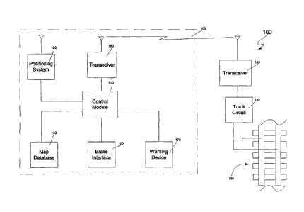
identical or corresponding parts throughout the several views, Figure 1 is a
logical
block diagram of a train control system 100 according to an embodiment of the
present invention. The train control system includes a train unit 105 and a
plurality
of pairs of track circuits 180 and transceivers 190 that monitor various
sections of
track 185. These track circuit 180/transceiver 190 pairs may be placed only at
certain locations on the track 185 (e.g., only near mountainsides when the
track
circuits 185 are of the form of avalanche detection circuits), or may be
positioned
such that the entire length of track is monitored. It should also be noted
that the
track circuit 180 is not necessarily connected to the track rails themselves
as is
shown in Fig. 1. For example, avalanche detection circuits are typically
connected
to slide fences rather than to the track itself. In this case, the circuits
detect breaks
in the slide fences, which indicate that debris has broken through the fence
and,
potentially, onto the track.
The train unit 105 includes a control module 110, which typically, but not
necessarily, includes a microprocessor. The control module 110 is responsible
for
controlling the other components of the system.
A positioning system 120 is connected to the control module 110. The
positioning system supplies the position (and, in some cases, the speed) of
the train
to the control module 110. The positioning can be of any type, including a
global
positioning system (GPS), a differential GPS, an inertial navigation system
(INS),
or a Loran system. Such positioning systems are well known in the art and will
not
be discussed in further detail herein. (As used herein, the term "positioning
system" refers to the portion of a positioning system that is commonly located
on a
mobile vehicle, which may or may not comprise the entire system. Thus, for
example, in connection with a global positioning system, the term "positioning
-5-

CA 02498927 2005-03-14
WO 2004/033267
PCT/US2003/032424
system" as used herein refers to a GPS receiver and does not include the
satellites
that transmit infonnation to the GPS receiver.)
A map database 130 is also connected to the control module 110. The map
database 130 preferably comprises a non-volatile memory such as a hard disk,
flash
memory, CD-ROM or other storage device, on which map data is stored. Other
types of memory, including volatile memory, may also be used. The map data
preferably includes positions of all track circuits in the railway. The map
data
preferably also includes information concerning the direction and grade of the
track
in the railway. By using train position information obtained from the
positioning
system 120 as an index into the map database 140, the control module 110 can
determine its position relative to track circuits.
When the control module 110 determines that the train is approaching a
track circuit 180 (which includes a transceiver 190) that monitors a section
of track
185 and is within range for conducting communications, it interrogates the
device
180 through transceiver 150. The transceiver 150 can be configured for any
type
of communication, including communicating through rails and wireless
communication. In addition to communicating with track circuit transceivers
190,
the transceiver 150 may communicate with transceivers connected to other
devices
such as switches and grade crossing gates, and may also communicate with a
dispatcher (not shown in Figure 1) from whom route information and track
warrants and authorities are received. In other embodiments, separate
communications devices are used for wayside device communication and
communication with a dispatcher.
Also connected to the control module 110 is a brake interface 160. The
brake interface 160 monitors the train brakes and reports this information to
the
control module 110, and also allows the control module 110 to activate and
control
the brakes to stop or slow the train when necessary.
A warning device 170 is also connected to the control module 110. The
warning device 170 is used to warn the conductor/engineer that a malfunction
has
been detected. The warning device 170 may also be used to allow the engineer/
-6-

CA 02498927 2009-05-06
conductor to acknowledge the warning. In some embodiments, the warning device
170
is in the form of a button on an operator display. In other embodiments, the
warning
device 170 may be a stand-alone button that illuminates when a malfunction is
detected. In yet other embodiments (e.g., those in which no acknowledgment of
a
warning is required), the warning device 170 may comprise or consist of a horn
or other
device capable of providing an audible wanting.
Figure 2 is a flowchart 200 illustrating operation of the control module 110
in
connection with a track circuit 180 in one embodiment of the invention. In
this
embodiment, which is particularly well suited for use with track circuits such
as broken
rail detection circuits and avalanche detection circuits, the train will be
preferably be
brought to a complete halt, either by the operator or automatically by the
control
module 110 if the operator fails to take action, before reaching the section
of track
monitored by the track circuit. Forcing the train to come to a complete stop
forces an
operator to take a positive decision to move the train forward through the
section of
track indicated as bad, thereby dramatically decreasing the chances that the
operator
will miss the warning provided by the track circuit. In some embodiments of
the
invention, permission from the dispatcher is required before the control
module 110
will allow the train to move again.
The control nodule 110 begins the process by obtaining the locations of nearby

track circuits 180 from the map database 130 at step 210. The control module
110 then
determines the train's current position from information provided by the
positioning
system 120 at step 212. If no track circuit 180 is within a threshold
distance, steps 210
et seq. are repeated. If a track circuit 180 is within a threshold distance at
step 214, the
transceiver 190 associated with the track circuit 110 is interrogated at step
216.
7

CA 02498927 2005-03-14
WO 2004/033267
PCT/US2003/032424
In some embodiments, this threshold distance is a predetermined distance
based upon the communication ranges of the transceiver 150 on the train and
the
transceiver 190 connected to the track circuit 180. In other embodiments, the
threshold distance is equal to a distance required to stop the train under a
worst -
case assumption (i.e., an assumption that a train having the greatest possible
weight
is traveling at a maximum allowable or possible speed in a downhill direction
on a
portion of track with the steepest grade in the system) plus an offset to
allow the
track circuit to perform the track test and respond to the interrogation. In
yet other
embodiments, the threshold is dynamically determined based on the actual speed
and weight of the train and the grade of the track between the train and the
track
circuit such that there is sufficient time for the track circuit 180 to test
the track 185
and report the results in response to the interrogation. In other embodiments,
the
calculation may take into account the distribution of weight in the train as
this will
effect the required stopping distance as discussed in the aforementioned co-
pending U.S. patent application.
In some embodiments, the interrogation includes an identification number
associated with the track circuit 180. This identification number is obtained
from
the map database 130. Only the track circuit corresponding to the
identification
number will respond to the interrogation. This avoids contention between
multiple
devices (track circuits or other devices - e.g., switches, crossing gates,
etc.)
attempting to respond to the interrogation on the same frequency. Thus, by
assigning unique device numbers to track circuits and other devices, all
devices can
share the same frequency.
If the track circuit 180 fails to respond at step 218, or reports a problem
with the track at step 220, the control module 110 warns the
conductor/engineer of
the problem via the warning device 170 at step 224. The control module 110
then
determines whether the brakes have been activated at step 226 by communicating

with the brake interface 160 directly and/or by obtaining speed information
from
the positioning system 120. Preferably, the control module 110 calculates the
braking force necessary to stop the train prior to reaching the section of
track
-8-

CA 02498927 2005-03-14
WO 2004/033267
PCT/US2003/032424
monitored by the track circuit 180 taking into account the speed and weight of
the
train, the distribution of the weight on the train, the grade of the track,
and the
characteristics of the braking system itself. If the operator has not
activated the
brakes in a manner sufficient to stop the train in time at step 226, the
control
module 110 automatically activates the brakes to stop the train at step 228.
If the track circuit 180 responds to the interrogation at step 218 and reports

that the track 185 is intact at step 220, then the control module 110 returns
to step
210 to repeat the process. Returning to step 210 will result in interrogating
the
track circuit 180 device multiple times as the train approaches. This is
desirable
for safety purposes because it will detect any problems that occur after the
initial
interrogation (e.g., a vandal dislodging a rail) from causing and accident.
Whether or not the interrogation of step 218 includes the device's
identification number, it is preferable for the device's response to include
its
identification number as this allows for greater assurance that a response
from
some other source has not been mistaken as a response from the track circuit
180 of
interest.
Figures 3a and 3b together form a flowchart 300 illustrating operation of
the control unit 110 in connection with configurable devices 180 according to
a
second embodiment of the invention. This embodiment allows a train to proceed
through a section of track at a reduced speed such that the train can be
stopped if
the operator visually determines that there is a problem with the track (e.g.,
a
broken rail or another train on the tracks) rather than forcing the train to
come to a
complete halt. This is done because track circuits sometimes give a false
indication of a problem. Steps 310-320 of the flowchart 300 are similar to
steps
210-220 of the flowchart 200 of Figure 2; therefore, the detailed discussion
of
these steps will not be repeated.
If a track circuit 180 does not respond at step 318 or reports a problem with
the track 185 at step 320 after being interrogated at step 316, the control
module
110 activates the warning device 170 at step 330. When the warning device 170
is
activated, the operator/engineer is given a period of time in which to
acknowledge
-9-

CA 02498927 2005-03-14
WO 2004/033267
PCT/US2003/032424
the warning and slow the train to a speed that is slow enough to allow the
operator
to stop the train before reaching a problem (e.g., a broken rail or another
train on
the track) that the operator detects visually. This period of time may be
predetermined based on a worst-case assumption of required distance to stop
the
train if the operator doesn't acknowledge the problem and slow the train to
the safe
speed, or may be determined dynamically based on factors such as the current
speed of the train, the braking characteristics of the brakes on the train,
the weight
of the train, the distribution of weight on the train, and/or the grade of the
track as
determined from the map database 130 using the train position from the
positioning system 120, as well as other factors that affect the required
stopping
distance/time.
If the operator acknowledges the warning at step 332 and reduces the speed
of the train to the safe speed at step 334 within the allowable time period,
the
control module 110 monitors the train's speed such that the reduced speed is
maintained at step 336 until the train has passed through the section of track
monitored by the track circuit 180 at step 338.
If the conductor/engineer fails to acknowledge the warning at step 332 or
fails to reduce the train's speed to the safe speed at step 334 within the
allowed
time period, the control module 110 commands the brake interface to stop the
train
at step 342. The control module 110 then notifies the dispatcher of the
stopped
train at step 344.
One advantage of those embodiments of the invention in which a
configurable device is interrogated as the train approaches is that such
devices are
not required to transmit information when trains are not in the area. This
saves
power as compared to those systems in which wayside devices continuously or
periodically transmit information regardless of whether a train is close
enough to
receive such information.
As discussed above, preferred embodiments of the invention include an
identification number in the interrogation messages sent to transponders 190
associated with track circuits 180. However, it is also possible to transmit
-10-

CA 02498927 2005-03-14
WO 2004/033267
PCT/US2003/032424
interrogation messages without identification numbers, in which case each
transporter that receives the interrogation will respond and include an
identification
number in its response. In either case, this allows all transponders to share
the
same frequency, which reduces complexity and cost.
In the embodiments discussed above, the control module 110 is located on
the train. It should also be noted that some or all of the functions performed
by the
control module 110 could be performed by a remotely located processing unit
such
as processing unit located at a central dispatcher. In such embodiments,
information from devices on the train (e.g., the brake interface 160) is
communicated to the remotely located processing unit via the transceiver 150.
One particularly important advantage of the invention is that it facilitates
use of track circuits in remote areas. That is, because an approaching train
transmits an interrogation message, the track detection circuit need only be
"on"
when the train approaches and may be in a low-power standby or off state with
the
transceiver in a low power "listening state" at other times when no train is
nearby.
This in turn facilitates the use of solar cells as a power source for these
track
circuit/transponder combinations. Furthermore, no high-maintenance mechanical
device is required to detect the presence of the train. An important
consequence of
this is that the invention provides the ability to include broken rail
protection in
dark territory in which no power source is available at low cost.
Another important aspect of the invention is its failsafe nature. Because the
control unit 110 ensures that corrective action is taken if the track circuit
180 does
not respond to an interrogation, there is no danger if the track circuit 180
and/or the
track circuit transceiver 190 fails to respond, thereby making the system
failsafe.
This also eliminates the need to perfolin preventive maintenance.
Additionally, no
signal lights are necessary, which eliminates a failure mode. Maintenance
costs are
dramatically reduced as a consequence of these two aspects.
-11-
'

CA 02498927 2005-03-14
WO 2004/033267
PCT/US2003/032424
Obviously, numerous modifications and variations of the present invention
are possible in light of the above teachings. It is therefore to be understood
that
within the scope of the appended claims, the invention may be practiced
otherwise
than as specifically described herein.
-12-

Representative Drawing
A single figure which represents the drawing illustrating the invention.
Administrative Status

For a clearer understanding of the status of the application/patent presented on this page, the site Disclaimer , as well as the definitions for Patent , Administrative Status , Maintenance Fee  and Payment History  should be consulted.

Administrative Status

Title Date
Forecasted Issue Date 2016-06-14
(86) PCT Filing Date 2003-10-10
(87) PCT Publication Date 2004-04-22
(85) National Entry 2005-03-14
Examination Requested 2006-06-21
(45) Issued 2016-06-14
Expired 2023-10-10

Abandonment History

There is no abandonment history.

Payment History

Fee Type Anniversary Year Due Date Amount Paid Paid Date
Registration of a document - section 124 $100.00 2005-03-14
Application Fee $400.00 2005-03-14
Maintenance Fee - Application - New Act 2 2005-10-11 $100.00 2005-03-14
Request for Examination $800.00 2006-06-21
Maintenance Fee - Application - New Act 3 2006-10-10 $100.00 2006-09-19
Maintenance Fee - Application - New Act 4 2007-10-10 $100.00 2007-09-07
Maintenance Fee - Application - New Act 5 2008-10-10 $200.00 2008-09-23
Maintenance Fee - Application - New Act 6 2009-10-13 $200.00 2009-09-30
Registration of a document - section 124 $100.00 2010-06-03
Maintenance Fee - Application - New Act 7 2010-10-12 $200.00 2010-09-27
Maintenance Fee - Application - New Act 8 2011-10-10 $200.00 2011-09-22
Maintenance Fee - Application - New Act 9 2012-10-10 $200.00 2012-09-18
Maintenance Fee - Application - New Act 10 2013-10-10 $250.00 2013-09-26
Registration of a document - section 124 $100.00 2013-11-29
Registration of a document - section 124 $100.00 2014-05-28
Maintenance Fee - Application - New Act 11 2014-10-10 $250.00 2014-09-08
Maintenance Fee - Application - New Act 12 2015-10-13 $250.00 2015-09-09
Final Fee $300.00 2016-03-31
Maintenance Fee - Patent - New Act 13 2016-10-11 $250.00 2016-09-07
Maintenance Fee - Patent - New Act 14 2017-10-10 $250.00 2017-09-07
Maintenance Fee - Patent - New Act 15 2018-10-10 $450.00 2018-09-13
Maintenance Fee - Patent - New Act 16 2019-10-10 $450.00 2019-09-05
Maintenance Fee - Patent - New Act 17 2020-10-13 $450.00 2020-09-25
Maintenance Fee - Patent - New Act 18 2021-10-12 $459.00 2021-09-13
Maintenance Fee - Patent - New Act 19 2022-10-11 $458.08 2022-09-26
Owners on Record

Note: Records showing the ownership history in alphabetical order.

Current Owners on Record
SIEMENS INDUSTRY, INC.
Past Owners on Record
HICKENLOOPER, HARRISON THOMAS
INVENSYS RAIL CORPORATION
KANE, MARK EDWARD
QUANTUM ENGINEERING, INC.
SHOCKLEY, JAMES FRANCIS
SIEMENS RAIL AUTOMATION CORPORATION
Past Owners that do not appear in the "Owners on Record" listing will appear in other documentation within the application.
Documents

To view selected files, please enter reCAPTCHA code :


To view images, click a link in the Document Description column. To download the documents, select one or more checkboxes in the first column and then click the "Download Selected in PDF format (Zip Archive)" or the "Download Selected as Single PDF" button.

List of published and non-published patent-specific documents on the CPD .

If you have any difficulty accessing content, you can call the Client Service Centre at 1-866-997-1936 or send them an e-mail at CIPO Client Service Centre.


Document
Description 
Date
(yyyy-mm-dd) 
Number of pages   Size of Image (KB) 
Abstract 2005-03-14 1 60
Claims 2005-03-14 8 336
Drawings 2005-03-14 4 59
Description 2005-03-14 12 614
Representative Drawing 2005-03-14 1 12
Cover Page 2005-05-30 2 45
Claims 2006-06-21 9 314
Claims 2006-08-11 14 537
Description 2009-05-06 12 613
Claims 2009-05-06 14 539
Claims 2010-08-06 14 538
Claims 2011-11-15 13 553
Description 2014-01-22 16 795
Claims 2014-01-22 13 549
Representative Drawing 2016-04-20 1 7
Cover Page 2016-04-20 1 42
Prosecution-Amendment 2011-08-16 2 61
Prosecution-Amendment 2010-07-19 10 379
PCT 2005-03-14 1 54
Assignment 2005-03-14 9 353
Prosecution-Amendment 2006-06-21 11 359
Prosecution-Amendment 2006-06-21 1 39
Prosecution-Amendment 2006-08-11 16 582
Correspondence 2010-07-27 1 18
Assignment 2008-09-23 38 2,008
Prosecution-Amendment 2009-03-05 2 62
Prosecution-Amendment 2009-05-06 15 541
Prosecution-Amendment 2010-02-24 2 52
Assignment 2010-06-03 19 969
Prosecution-Amendment 2010-08-06 6 223
Prosecution-Amendment 2011-11-15 13 567
Prosecution-Amendment 2013-07-22 2 43
Correspondence 2013-11-29 4 122
Assignment 2013-11-29 7 261
Correspondence 2013-12-11 1 18
Correspondence 2013-12-11 1 21
Correspondence 2013-12-30 1 22
Prosecution-Amendment 2014-01-22 20 884
Assignment 2014-05-28 7 284
Correspondence 2015-01-15 2 65
Final Fee 2016-03-31 2 74