Note: Descriptions are shown in the official language in which they were submitted.
CA 02503268 2010-04-14
1. Field of the Invention
The present invention relates to data acquisition systems and methods for oil
and gas wells. In one aspect, the present invention relates to systems and
methodologies for determining temperature gradients in connection with thermal
recovery projects involving oil or gas wells.
2. Description of the Related Art
There exists throughout the world major deposits of heavy oils which, until
recently, have been substantially ignored as sources of petroleum since the
oils
contained therein were not recoverable using ordinary production techniques.
These oil deposits are also referred to as heavy oil, or bitumen. For example,
it
was not until the 1980's that much interest was shown in the heavy oil
deposits of
the Alberta province in Canada even though many deposits are close to the
surface and represent an estimated petroleum resource upwards of many billion
barrels.
It is well known that heat can be employed to recover hydrocarbons from
underground formations such as those found in the regions noted above. Often
referred to as thermal recovery projects, the well owner uses heat to reduce
the
viscosity of the petroleum to a level where it will readily flow to wells from
which it
can be recovered to the surface of the earth. Steam and/or hot water flooding
are
commonly used for this purpose and have been very successful in some
formations for stimulating recovery of viscous petroleum which is otherwise
essentially unrecoverable. Steam flooding is a thermal oil recovery method
which
-2-
CA 02503268 2005-04-19
has enjoyed increased popularity in recent years and is often the most
commercially practical method or process.
Steam flooding can be utilized in a single well by the so called "huff-and-
puff' technique. That method involves first injecting steam into a vertical
well,
then shutting in the well for a "soak", wherein the heat contained in the
steam
raises the temperature and lowers the viscosity of the petroleum. Thereafter,
a
production period begins wherein mobilized petroleum is produced from the
well,
usually by pumping. This process can be repeated over and over again.
Steam flooding may also be utilized as a thermal drive means by injecting
steam into the reservoir through one or more vertical injection wells. This
steam
then moves through the subterranean reservoir mobilizing and volatilizing the
petroleum it encounters. This steam-flood front moves through the reservoir
towards a production well wherefrom the petroleum fluids are produced. This
steam drive process is often more effective than the "huff-and-puff" method
inasmuch as the potential volume of the reservoir which can be swept by the
process is greater.
Alternate methods are also available to heat and mobilize the oil or
bitumen in the reservoir. These include the use of hot solvent, hot gas, hot
air as
well as underground burning or combustion.
Thermal oil recovery projects such as those described above require
temperature monitoring of the downhole temperature in the reservoir.
Conventionally, temperature data is obtained via sensors positioned in both
vertical observation wells and horizontal production wells. Historically,
monitoring of thermal oil reservoirs utilized either multi-point thermocouple
sensors or distributed temperature fiber optic cable in order to obtain multi-
point
readings and therefore infer a temperature profile in the reservoir. Many
individual points are desired and therefore it is necessary to obtain a
multitude of
COR-1094-US -3-
CA 02503268 2010-05-04
readings. Twenty points are often obtained in order to create a temperature
profile across the formation. Typically, a thermocouple (e.g., a mineral
insulated (MgO) thermocouple) is positioned at each selected temperature
measurement point in the wellbore and connected to a surface interface with
two
wires. As is known, two wires are required for each thermocouple because two
different alloys are connected together at the junction of the thermocouple.
As
can be appreciated, the costs of such wiring can become considerable because
the length traversed by the wires can approach several kilometers.
Furthermore, the data transmitted across these relatively long spans of wiring
or
cables can degrade and weaken and be corrupted by noise. The long lengths
are also prone to accuracy loss caused by wire impurities, insulation
breakdown,
and low voltage signal degradation. Likewise, fiber optic cables sensors as
well
as the associated fiber optic cables are relatively expensive and prone to
degradation in signal accuracy and strength due to hydrogen related problems
with the glass fiber. Moreover, in both instances, the splices or couplings
between individual lengths of cable can introduce noise and errors into the
transmitted data. Yet another difficulty and expense arises from the need to
effectively seal and pack-off multiple wires or multiple bundles of cables
exiting
the wellhead. As is known, effective wellhead sealing can be essential to
containing a well blow out.
The present invention addresses these and other drawbacks of the prior
art.
SUMMARY OF THE INVENTION
In aspects, the present invention provides a system for acquiring data
from a heat affected zone associated with a thermal recovery hydrocarbon
reservoir in a subterranean formation that is intersected by a wellbore. A
casing
is cemented in the wellbore. A primary tubing string is in the wellbore. A
coiled tubing string is positioned along the primary tubing string. A locking
assembly releasably couples the primary tubing string to the coiled tubing
string. The locking assembly is configured to be responsive to a signal
-4-
CA 02503268 2010-05-04
transmitted from the surface. A processor is positioned at a selected location
along a wellbore that intersects the reservoir, the selected location being
substantially outside of the heat affected zone. A plurality of sensors is
distributed along the primary tubing string and at least partially along the
heat
affected zone. A data link couples the processor to a surface interface.
In other aspects, the present invention provides a system for
determining a temperature gradient for a heat affected zone associated with a
thermal recovery hydrocarbon reservoir in a subterranean formation, the
reservoir being intersected by a wellbore and being heated by an artificial
source. A casing is cemented in the wellbore. A primary tubing string is in
the wellbore. A coiled tubing string is positioned along the primary tubing
string. A locking assembly releasably couples the primary tubing string to the
coiled tubing string. The locking assembly is configured to be responsive to a
signal transmitted from the surface. A plurality of temperature sensors is
distributed along the primary tubing string and at least partially along the
heat
affected zone, the temperature sensors providing temperature measurements.
A downhole processor is positioned outside of the heat affected zone. The
processor is programmed to receive and digitize the temperature
measurements. A data cable is coupled to the downhole processor. The
data cable is adapted to convey the temperature measurements to a surface
interface.
In still other aspects, the present invention provides a method for
acquiring data from a heat affected zone associated with a thermal recovery
hydrocarbon reservoir in a subterranean formation. The method includes
cementing a casing in a wellbore intersecting the formation. A primary tubing
string is positioned in the wellbore. A coiled tubing string is positioned
along
the primary tubing string. A locking assembly releasably locks the primary
tubing string to the coiled tubing string. The locking assembly is configured
to
-5-
CA 02503268 2010-05-04
be responsive to a signal transmitted from the surface. A processor is
positioned at a selected location along a wellbore that intersects the
reservoir,
the selected location being substantially outside of the heat affected zone. A
plurality of sensors is distributed along the primary tubing string, the
wellbore
and at least partially along the heat affected zone. The processor is coupled
to a surface interface with a data link. A signal is transmitted to cause the
locking assembly to unlock the primary tubing string from the coiled tubing.
It should be understood that examples of the more important features of
the invention have been summarized rather broadly in order that detailed
-5A-
CA 02503268 2005-04-19
description thereof that follows may be better understood, and in order that
the
contributions to the art may be appreciated. There are, of course, additional
features of the invention that will be described hereinafter and which will
form the
subject of the claims appended hereto.
BRIEF DESCRIPTION OF THE DRAWINGS
For detailed understanding of the present invention, references should be
made to the following detailed description of the preferred embodiment, taken
in
conjunction with the accompanying drawings, in which like elements have been
given like numerals and wherein:
FIG. 1A schematically illustrates one embodiment of a signal / data
communication system made according to one embodiment of the present
invention;
FIG. 1B graphically illustrates an exemplary temperature gradient
associated with a formation having a "heat affected zone;"
FIG. 2 schematically illustrates an elevation view of a vertical well
provided with a signal / data communication system made according to one
embodiment of the present invention;
FIG. 3 schematically illustrates an elevation view of a well having a
horizontal section that is provided with a signal / data communication system
made according to one embodiment of the present invention;
FIG. 4A schematically illustrates a sectional view of a coiled tubing
arrangement having a signal / data communication system made according to
one embodiment of the present invention;
COR-1094-US -6-
CA 02503268 2005-04-19
FIG. 4B schematically illustrates a sectional view of a coiled tubing
arrangement having a signal / data communication system made according to
one embodiment of the present invention;
FIG. 5 schematically illustrates a signal / data communication system
made according to one embodiment of the present invention that is deployed via
a coiled tubing system;
FIG. 6 schematically illustrates a signal / data communication system
made according to one embodiment of the present invention that is deployed via
another coiled tubing system;
FIG. 7 schematically illustrates an exemplary sensor arrangement.
positioned in an open hole;
FIG. 8 schematically illustrates an exemplary sensor arrangement
positioned external to equipment positioned in a wellbore;
FIG. 9 schematically illustrates an exemplary sensor arrangement
positioned internal to a wellbore tubular and adapted to indirectly measure a
parameter of interest outside of the wellbore tubular;
FIG. 1OA-10C schematically illustrates data carrier exemplary data carrier
arrangements for thermocouples used in accordance with embodiments of the
present invention;
FIG. 11A-11C schematically illustrates data carrier exemplary data carrier
arrangements for fiber optic sensors used in accordance with embodiments of
the present invention.
COR-1094-US -7-
CA 02503268 2005-04-19
Similar reference characters denote corresponding features consistently
throughout the attached drawings.
DETAILED DESCRIPTION OF THE PREFERRED EMBODIMENT
The present invention relates to devices and methods for acquiring and
transmitting signals / data from a welibore to a surface location. The present
invention is susceptible to embodiments of different forms. There are shown in
the drawings, and herein will be described in detail, specific embodiments of
the
present invention with the understanding that the present disclosure is to be
considered an exemplification of the principles of the invention, and is not
intended to limit the invention to that illustrated and described herein.
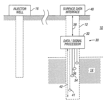
Referring initially to Fig. 1A, there is schematically an arrangement for
recovering hydrocarbons such as oil, heavy oil, or bitumen, from a
subterranean
formation 10. A wellbore 12 drilled into the formation 10 intersects a
hydrocarbon reservoir or pay zone 14. The wellbore 12 can include known
equipment such as a cemented casing. While one reservoir 14 is shown, it
should be understood that the wellbore 12 can intersect multiple pay zones.
Relative to the formation 10, the reservoir 14 has a relatively higher
temperature
that is attributed to natural sources or by an artificial source such as a
steam
injection well 16. The relatively higher temperatures can be considered to
define
a thermal oil zone, which can rise by enhanced thermal recovery, in geothermal
wells, in SAGD (steam assisted gravity drainage) wells, and other instances
where cyclic steam or a variety of other vapor or hot gas or hot liquid
injection
methods are used for thermal recovery.
Referring now to Fig. 113, there is shown a graph with depth D along the
vertical axis and temperature T along the horizontal axis. The Fig. 1B graph
shows a representative temperature gradient 18 for the formation 10 of Fig.
1A.
As can be seen, the temperature gradient 18 has two portions or intervals: a
COR-1094-US -8-
CA 02503268 2005-04-19
"heat affected zone" 20 associated with the reservoir 14 and a relatively
cooler
zone 22. It should be understood that the term "heat affected zone" generally
refers to a region or zone where the prevailing temperature is higher than the
natural geothermal temperature at that depth. The formation zone temperature
is
elevated by an artificially induced process that causes the oil or bitumen to
flow.
The term "heat affected zone" also refers to a region or zone where a
naturally
occurring heat sources raises the temperature to a level higher than what
would
otherwise occur at that depth. The elevated temperature can be outside the
normal or recommended range of temperatures for a given tool, device,
instrument, or operating condition. Thus, the term "heat affected zone" does
not
necessarily imply a specific temperature or temperature range. Rather, a zone
can be considered "hot" if the ambient temperature compromises or impairs the
structural integrity, operating efficient, operating life, or reliability of a
given tool,
device, or instrument. The "heat affected zone" can be induced by one or more
injector wells 16 or other suitable sources.
The determination of the temperature gradient for the reservoir 14 and
elsewhere can be made by a downhole data acquisition system 30 that includes
a downhole processor 32 and one or more sensors 34 that transmit data via one
or more data carriers 36 to the processor 32. The downhole processor 32 is a
device adapted to process data and can include, but is not be limited to a
digitizer, multiplexing device, switching device, microprocessor, digital
circuitry,
analog circuitry, optical filtering device, wave division multiplexor, laser
diodes,
and lasers. The downhole processor 32 processes the sensor data and
transmits the processed data via a communication / transmission link 38 to a
surface signal / data receiving interface 40. Although one set of sensors 34
is
shown for zone 14, other sensors 41 can be positioned in other locations of
the
wellbore 12. Additionally, additional communication / transmission links 42
can
be used to provide data transfer between the downhole processor 32 and other
processors (not shown) positioned elsewhere in the wellbore 12.
COR-1094-US -9-
CA 02503268 2005-04-19
As used in this description, the term data carrier refers to one or more
elements that can transmit at least data signals. The transmission can include
electrical signals, magnetic signals, pressure pulses, and optical signals.
Suitable elements include but are not limited to metal conductors, fiber optic
cables, hydraulic conduits. Moreover, terms such as wires, cable, or cable
bundle are used interchangeably and imply no particular configuration.
Moreover, the term data carrier and data links are merely used to conveniently
refer to the data transmission between the sensors and the processor and
between the processor and the surface. Accordingly, no structural or
functional
differences are intended by such terminology (e.g., data links can include
wires
or cables and data carriers can include radio or electromagnetic wave).
In one embodiment, the sensors 34 are positioned along the heat affected
zone 20 and include temperature sensors that transmit temperature
measurements via the data carriers 36 to the processor 32. The temperature
sensors can include thermocouple elements, resistive thermal devices (RTDs),
thermistors, semiconductors junction (diodes), and fiber-optic sensors. Such
sensors are well known devices and thus will not be discussed in further
detail.
Merely for convenience, thermocouples will be used as a representative
temperature sensor. The processor 32 can include a multi-channel digitizer to
digitize signal data, programs or algorithms to condition data (e.g.,
filtering noise,
decimating data, etc.), and/or other suitable electronics for processing,
recording,
and transmitting data. The processor can also include known equipment not
shown such as a power source, a signal booster to amplify signals that may
weaken during transmission, and a transceiver transmitting data. It may also
include any combination of but not be limited to a digitizer, multiplexing
device,
switching device, microprocessor, digital circuitry, analog circuitry, optical
filtering
device, wave division multiplexor, lasor diodes, and lasers. In one
arrangement,
the processor 32 is programmed to receive temperature data from multiple
thermocouples, digitize the temperature data, and transmit the temperature
data
to the surface via the communication link 38.
COR-1094-US -10-
CA 02503268 2005-04-19
The communication link 38 provides one-way or bi-directional
transmission of data / signals between the processor 32 and the surface
interface
40. The communication link 38 can include conductors such as electrical
conductors and/or a fiber optic wires and/or one or more transmitters that use
transmission media such as acoustical signals, radio frequency signals, and/or
electromagnetic signals. Moreover, the communication link 38 can include a
train of relay stations that relay signals uphole and/or downhole.
Additionally the
communication link may deliver power to the downhole tool and simultaneously
allow communication to surface either through one electrical conductor, and/or
a
fiber optic fiber or multiple electrical conductors, and/or optic fibers.
Additionally,
in applications where the processor 32 or other downhole equipment require
electrical power, the communication link 38 can include suitable power
conductors such as electrical power cables. It should be appreciated that
there
is a fractional relationship between the number of data carriers 36 associated
with the sensors 34 and the communication link 38. For instance, six carriers
36
can connect the sensors 34 to the processor 32 whereas one data cable (not
shown) associated with the communication link 38 can connect the processor 32
to the surface interface 40. This six-to-one fractional relationship is merely
illustrative. Other illustrative fractional relationships include forty sensor
carriers
to one communication link or twenty four sensor carriers to two communication
links. Generally speaking, therefore, fewer communication links such as wires
or
cables are needed than thermocouple data carriers. One advantage resulting
from this relationship is a reduction in wires or cables between the processor
32
and the surface interface 40. Minimizing the number of wires or cables in the
wellbore 12 can facilitate manufacturing, design, deployment, and maintenance
in several aspects. For example, a single cable can be more easily sealed at a
wellhead than multiple cables. Maintaining adequate seals at the wellhead is,
of
course, of significant concern because hydrocarbons in a wellbore can
sometimes be at relatively high-pressure. Failure of seals can lead to a well
blowout, a hazardous condition for personnel and equipment.
COR-1094-US -11-
CA 02503268 2005-04-19
Another advantage to effectively replacing multiple thermocouple wiring
with a fractional number of communication links (e.g., one cable) is that
thermocouple data carriers (e.g., mineral insulated thermocouples) are usually
more expensive than devices / equipment for the communication link such as
electrical cables. Thus, minimizing the length of thermocouple wiring will
generally reduce the overall cost of the system 30.
Because the processor 32 operates as a transfer or relay mechanism
between the thermocouple wiring and the communication link, it is advantageous
to position the processor 32 as close as possible to the sensors 34 to reduce
overall system cost. However, as noted above, the sensors 34 are positioned
generally within the heat affected zone 20. The appropriate distance from the
processor 32 to the sensors 34 and the heat affected zone 20 depends in part
on
the constituent components of the processor 32 and the rated operating
conditions of these components. In some arrangements, the processor 32 can
be inside or immediately adjacent to the heat affected zone 20 and be exposed
to elevated temperatures if the processor 32 is sufficiently resistant to
relatively
high temperatures. Alternatively, the processor 32 can be positioned
sufficiently
far from the heat affected zone 20 such as to limit exposure to potentially
harmful
elevated ambient temperatures. In one arrangement, the processor 32 is
positioned outside and adjacent to the heat affected zone 20.
Yet another advantage to effectively multiple thermocouple or fiber optic
wiring with a fractional number of communication links (e.g., one cable) is
that
early conditioning and/or conversion of the temperature data and transmission
of
the conditioned / converted data across more robust communication devices can
enhance overall data reliability and accuracy. As previously discussed, data
transmitted across thermocouple data carriers are susceptible to degradation
from factors such as noise and signal strength can weaken in relatively long
lengths of thermocouple wiring.
COR-1094-US -12-
CA 02503268 2005-04-19
Referring now to Fig. 2 there is shown a hydrocarbon recovery facility 43
for recovering hydrocarbons such as oil and gas from a generally vertical
wellbore 44 formed in a formation 45. A wellhead 49 and associated equipment
is positioned over the wellbore 44. The formation 45 has a hydrocarbon layer
46
and an associated heat affected zone 48 created artificially using previously
described equipment and methodologies. An illustrative data acquisition system
50 for measuring temperature in the heat affected zone 48 and/or other
downhole locations includes a multi-channel A/D processor 52, one or more
thermocouples 54 and wiring 56 connecting the thermocouples 54 to the
processor 52. In an exemplary arrangement, the thermocouples 54 are
distributed across the heat affected zone 48 so that surface personnel can
develop a temperature gradient for the hydrocarbon layer 46. This temperature
gradient can be useful for determining the efficiency of the artificial
heating
and/or overall efficiency of the hydrocarbon recovery process. The processor
52
is uphole but proximate to the heat affected zone 48. During operation, the
processor 52 converts analog temperature measurements from the
thermocouples 54 to digital data and transmits the digital data via a downhole
data link 58 and surface communication link 60 to a surface processor 62. The
downhole data link 58 includes an insulated cable 61 suitable for a wellbore
environment. The surface processor 62 can include suitable electronics to
display, record, and/or analyze the received data. In an exemplary arrangement
the processor could also be located below the heat affected zone and the
communication cable traverses the zone, thus communicating the information to
surface.
It should be appreciated that by utilizing the downhole processor 52 and
data link 58, the Fig. 2 arrangement significantly reduces the amount of
wiring 56
that would otherwise be required to obtain temperature data from the
thermocouples 54 in the heat affected zone 48. Moreover, by positioning the
processor 52 outside of the heat affected zone 48, the Fig. 2 reduces the
COR-1094-US -13-
CA 02503268 2005-04-19
complexity and expense related to designing and manufacturing electronic
components capable of withstanding ambient temperatures that could approach
exceed 150-300 degrees Centigrade in the heat affected zone 48. It should be
understood, however, that the processor 52 may still encounter relatively
higher
ambient temperature conditions than the natural geothermal gradient of the
well,
but those temperatures do not materially degrade the operation, function or
life of
the processor 52.
Also, as Fig. 2 illustrates, a single cable 61 extends from the processor 52
to the surface. Thus, a seal assembly 63 for the cable 61 at the wellhead 49
can
be configured as a single seal rather than a plurality of individuals seals.
Referring now to Fig. 3 there is shown a hydrocarbon recovery facility 70
for recovering hydrocarbons such as oil and gas from a wellbore 72 having a
horizontal section 73 that is formed in a formation 74. A wellhead 76 and
associated equipment is positioned over the wellbore 72. The formation 74 has
a
hydrocarbon layer 75 and an associated heat affected zone 78 created
artificially
using previously described equipment. An illustrative data acquisition system
70
for measuring temperature in the heat affected zone 78 and/or other downhole
locations includes a multi-channel A/D processor 82, one or more temperature
sensors 84 and conductors 86 connecting the sensors 84 to the processor 82. In
an exemplary arrangement, the sensors 84 are distributed across the heat
affected zone 78 so that surface personnel can develop a temperature gradient
for the hydrocarbon layer 75. The processor 82 is uphole but proximate to the
heat affected zone 78. During operation, the processor 52 converts analog
temperature data to digital data and transmits the digital data via a downhole
data link 88 and surface communication link 89 to a surface processor 90. The
downhole data link 88 includes a downhole transmitter 92 and a surface
transmitter 94. The transmitters 92 and 94 can be one-directional or bi-
directional. The wireless data link 88 can use a transmission media such as
acoustical signals, radio frequency signals, pressure pulses and/or
COR-1094-US -14-
CA 02503268 2005-04-19
electromagnetic signals wireless data / signal transmission arrangements
suitable for a welibore environment.
The data acquisition systems discussed above are amenable to numerous
embodiments. Merely for illustration, there is shown in Fig. 4A one embodiment
of aspects of a data acquisition system 100 adapted for use with coiled tubing
102. The data acquisition system 100 includes a downhole processor 104,
temperature sensors 106 and associating wiring 108 between the sensors 106
and the processor 104. The coiled tubing 102 has an open end 110 that allows
welibore fluid to flood the interior of the coiled tubing 102 and enable the
sensors
106 to measure a parameter of interest relating to the wellbore fluid such as
pressure, temperature, chemical make-up, etc. As shown, the downhole
processor 104 is positioned in the coiled tubing 102 and transmits temperature
data via a communication link 112 to the surface. The processor 104 can
include
suitable electronics and software to process temperature data such as an
analog-to-digital converter (A/D converter or "digitizer"). As is known, the
coiled
tubing 102 can be a continuous tubular or made up of segments or sections that
are coupled together using suitable connectors. Depending on the application,
the processor 104 and/or sensors 106 can inside of one continuous length of
coiled tubing or production tubing with no subs or ports, positioned inside a
coiled
tubing segment, in a connector coupling two coiled tubing segments, in a top
sub
at the uphole end of a coiled tubing string, or a sub that is interposed
between
coiled tubing segments. Alternatively, the processor 104 can be a separate
unit
that is positioned external (e.g., adjacent or uphole) to the coiled tubing
102.
Referring now to Fig. 4B, there is shown another embodiment of a data
acquisition system 120 adapted for use with coiled tubing 122. The data
acquisition system 120 includes a downhole processor 124 that transmits
temperature data via a communication link 125 to the surface, temperature
sensors 126 and associating wiring 128 between the sensors 126 and the
processor 124. The processor 124 can include suitable electronics and/ or
COR-1 094-US -15-
CA 02503268 2005-04-19
software to process temperature data such as an A/D converter. The coiled
tubing 122 has a closed end 130 that prevents wellbore fluids from entering
the
interior of the coiled tubing 122. Communication between the sensors 126 and
the wellbore fluids is enabled by ports 132 formed in the coiled tubing 122.
The
ports 132 can be pre-formed or cut into coiled tubing segments or sections.
Alternatively, a sub can be constructed with the system 120 and connected to
an
end of the coiled tubing or between sections of coiled tubing.
Referring now to Fig. 5, there schematically shown another embodiment
of a data acquisition system 140 for monitoring temperature of a heat affected
zone 144 associated with a hydrocarbon reservoir 146. The data acquisition
system 140 includes a primary tubing string 148 and a string of coiled tubing
150.
The primary tubing string 148 and coiled tubing 150 are secured together at
their
bottom ends by a locking assembly 152. The locking assembly 152 can include
mechanical devices or electro-mechanical devices for selectively locking
together .
the primary tubing string 148 and coiled tubing 150. For example, suitable
mechanical devices include interlocking arms or splines, a spring detent,
biased
members (e.g., piston), and shear pins. Devices such as hydraulic or electric
motors can also be used to actuate the elements of the locking assembly 152.
Additionally, the locking arrangement can use one or more locking members
formed of a material responsive to an input such as thermal energy, kinetic
energy, chemical reaction, an electrical signal or a magnetic field; e.g., the
input
responsive material can melt, disintegrate, combust, explode, or change
material
states (e.g., change from solid to liquid) to release the primary tubing
string 148
from the coiled tubing 150. The locking assembly 152 can be actuated from the
surface using a signal or actuated by a pre-set condition while downhole such
as
a timer, pressure variance, mechanical manipulation of a cable, or tubing
string,
or having a natural or induced temperature change or other means.
The data acquisition system 140 includes a processor 154 positioned
outside and adjacent to the heat affected zone 144, sensors 156 positioned
COR-1094-US -16-
CA 02503268 2005-04-19
along the primary tubing string 148, conductors 158 coupling the sensors 156
to
the processor 154, and a data transmission link 160 that transmits data
signals
from the processor 154 to a surface processor (not shown). In an exemplary
installation sequence, the relevant components of the data acquisition system
140 are installed into the primary tubing string 148. Thereafter, the primary
tubing string 148 and coiled tubing 150 are connected together using the
locking
assembly 152. The primary string 148 and coiled tubing 150 are lowered into
the
wellbore 162 and positioned as needed. In a "piggy back" fashion, coiled
tubing
150 is carried or pulled into the wellbore, particularly a deviated section of
the
wellbore, by the the primary string 148 . Either by a surface signal or upon
application of an input or occurrence of a condition (e.g., a temperature,
pressure, depth, time duration), the locking assembly 152 is actuated to
release
the primary string 148 from the coiled tubing 150. The coiled tubing string
150
can then be extracted from the wellbore 162. In other arrangements the coiled
tubing may also be banded together to the tubing string that allows both
devices
to be lowered into the wellbore together. It should be understood that this
sequence is merely illustrative and can be re-arranged as needed for a given
situation or system configuration.
Referring now to Fig. 6, there is schematically shown a data acquisition
system 180 for measuring a heat affected zone 182 associated with a
hydrocarbon reservoir 184. The data acquisition system 180 can be run in an
instrumentation string 186 run parallel with a tubular string 188. The data
acquisition system 180 includes a processor 190 positioned outside and
adjacent
to the heat affected zone 182, thermocouples (not shown) positioned along the
instrumentation string 186, conductors (not shown) coupling the sensors to the
processor 190, and a data transmission link 192 that transmits data signals
from
the processor 190 to a surface processor (not shown). For illustrative
purposes,
there is shown another processor 191 positioned within the heat affected zone
182. The processor 191 can be in addition to or in lieu of the processor 190.
COR-1094-US -17-
CA 02503268 2005-04-19
The processor 191 is adapted for operation in the relatively hot environment
of
the heat affected zone 182.
In the Fig. 6 embodiment, which can include features discussed in Fig.
4A-B, the instrumentation string 186 includes a plurality of tubular segments
194
connected together by a plurality of tubular subs 196. The subs 196 are
positioned at spaced apart locations where sensor measurements such as
pressure and/or temperature are to be taken. Each sub 196 has a port 200 for
communicating with the reservoir 184. A plurality of hard-wired temperature-
measuring thermocouple sensors (not shown) extend from each sub 196 to the
processor 190. The sensors (not shown) are operatively connected with the
ports 200 at the various measurement locations. It should be understood that
the
terms "subs" and "segments" are used in their functional sense rather than the
structural sense. For example, a coiled tubing segment can be modified to
include ports. The section so modified thereby becomes the "sub". Thus, the
subs are not necessarily structurally separate from the coiled tubing
segments.
In an embodiment functionally and structurally equivalent to that shown in
Fig. 6, a single continuous string of coiled tubing is modified by cutting
windows
at spaced apart intervals along the coiled tubing. One or more sensors and/or
processors are inserted into the side of the coiled tubing string followed by
the
window being closed by welding or bolting.
While embodiments of the present invention have been discussed in the
context of coiled tubing, any number of arrangements can be used to instrument
a vertical and/or a horizontal well with temperature sensors to obtain
temperature
gradients or profiles for a selected heat affected zone. For example, the data
acquisition system can be position outside of wellbore equipment such as
casing,
cemented in an open hole, and deployed either inside or outside wellbore
equipment and tubulars such as drill pipe, production pipe, casing, liner,
slotted
liner or screen, or on the inside or outside of tubing or coiled tubing.
Referring
COR-1094-US -18-
CA 02503268 2005-04-19
now to Fig. 7, there is shown a sensor package 220 in an open hole section 222
of a wellbore 224. The sensor package 220 can optionally be cemented in
place. Referring now to Fig. 8, there is shown a sensor package 230 positioned
outside a casing, liner, or screen 232 in a wellbore 234. The casing liner or
screen can be slotted or unslotted. The sensor package 220 can optionally be
cemented in place during cementing of the casing liner, or screen 232.
Referring now to Fig. 9, there is shown an instrumentation string 260
formed of tubing 262 having a sealed end 264. The tubing 262 can be coiled
tubing, production tubing, drill pipe, liners, casing, or other tubulars used
in a
wellbore. Sensors 266 mounted inside the tubing 264 indirectly measure one or
more selected parameters such as pressure or temperature by sensing a
phenomena related to an effect outside of the coiled tubing 262. For example,
an approximate temperature outside the tubing 262 can be obtained through
thermal conduction of the temperature through the wall of the tubing 262 to a
temperature sensor 266 located inside the tubing 262. In another example, a
strain sensor 266 mounted inside of the tubing 262 indirectly measures the
strain
or stressed applied to the tubing 262 or adjacent material such as cement,
fluid
or an earthen formation. In other embodiments, the tubing 262 remains open,
i.e., does not have a sealed end 264.
Referring now to Figs. 10A-10C, there are shown illustrative
arrangements for data carriers suitable for connecting a thermocouple to a
processor. Fig. 10A illustrates a basic arrangement, or "simplex," wherein a
pair
of conducting wires 300 made from different metals connect a thermocouple end
point 302 to a processor (not shown). Fig. 10B illustrates a "duplex"
arrangement wherein a lead conducting wire 310 from a processor (not shown)
connects to a first and a second thermocouple end point 312, 314 but each
thermocouple end point 312,314 has a separate return wire 316,318 respectively
connecting to a processor (not shown). The lead wire 310 is made from metal
different from the return wires 316,318. Fig. 10C illustrates a "triplex"
COR-1094-US -19-
CA 02503268 2005-04-19
arrangement wherein a lead conducting wire 320 from a processor (not shown)
connects to a first, a second, and a third thermocouple end point 322,324,326
but
each thermocouple end point 322,324,326 has a separate return wire
328,330,332 respectively connecting to a processor (not shown). The lead wire
320 is made from metal different from the return wires 328,330,332.
Referring now to Figs. 11A-11 C, there are shown illustrative
arrangements for data carriers adapted for use in conjunction with fiber optic
sensors. A fiber optic system can be configured to multiplex multiple fiber
optic
sensors on the same fiber using frequency division techniques and thereby
reduce the number of wires or cables connecting individual sensors to a
processor. Fig. 11A illustrates an arrangement wherein individual wires 400
connect each fiber optic sensor 402 to a processor (not shown). Fig. 11B
illustrates an arrangement wherein one fiber optic cable 410 from a processor
(not shown) connects to a first and a second fiber optic sensors 412, 414. The
processor (not shown) communicates with each sensor 412,414 via a different
frequency, thereby enabling the use of a single cable 410. Fig. 11C
illustrates an
arrangement wherein a fiber optic wire 420 from a processor (not shown)
connects to a first, a second, and a third fiber optic sensor 422,424,426 via
branches 428,430,432. As can be see, the above-described arrangements allow
multiple sensors to be connected to the processor using one or more fiber data
carriers.
From the above, it should be appreciated that in aspects the present
invention provides systems and methods for obtaining parameter measurements
from selected locations in a wellbore associated with thermal recovery
projects.
Because the selected locations can be distributed along zones of interest,
such
as a heat affected zone, a well operator can determine a profile or gradient
for a
selected parameter of interest. While temperature measurements have been
discussed at length above, it should be appreciated that the teachings of the
present invention can also be used to obtain pressure measurements, fluid flow
COR-1094-US -20-
CA 02503268 2005-04-19
rates, fluid make up, and other parameters relating to the weilbore
environment.
In other aspects, sensors used in connection with the present invention can be
used to monitor one or more parameters relating to the condition of weilbore
tubulars and equipment. Exemplary sensors for such applications include casing
corrosion monitors, casing and tubular strain sensors.
The foregoing description is directed to particular embodiments of the
present invention for the purpose of illustration and explanation. It will be
apparent, however, to one skilled in the art that many modifications and
changes
to the embodiment set forth above are possible without departing from the
scope
of the invention. It is intended that the following claims be interpreted to
embrace
all such modifications and changes.
COR-1094-US -21-