Note: Descriptions are shown in the official language in which they were submitted.
CA 02503372 2009-07-27
INFORMATION STORAGE MEDIUM AND METHOD OF
RECORDING/ REPRODUCING THE SAME
Technical Field
The present invention relates to an information storage medium having
user data areas and additional data areas and a method of reproducing
information recorded on the information storage medium, and more particularly,
to an information storage medium having an improved, structure in which user
data areas are distinguished from additional data areas and a method of
recording information thereon and/or reproducing information from the
information storage medium.
Background Art
Optical discs are generally used as information storage media of optical
pickup devices which record information on and/or reproduce information from
the optical discs without contacting the optical discs. Optical discs are
classified
as either compact discs (CDs) or digital versatile discs (DVDs) according to
their
information recording capacity. Optical discs can also be classified as either
recordable discs or read-only discs according to their recording potential.
Here,
the recordable discs include 650MB CD-Rs, CD-RWs, 4.7GB DVD+R/RWs, DVD-
random access memories (DVD-RAMs), DVD-R/rewritables (DVD-R/RWs), and so
forth. The read-only discs include 650MB CDs, 4.7GB DVD-ROMs, and the like.
Referring to FIG. 1, the recordable information storage medium includes
user data areas A and additional data areas B located before and after the
user
data areas A. Here, the user data areas A are physical clusters in which data
is
recorded. The additional data areas B are divided into run-in areas and run-
out
areas.
1
CA 02503372 2009-07-27
The additional data areas B serve as spare areas in which data can be
recorded even when a recording position of the information storage medium is
changed with a variation in the speed of a spindle motor during rotating of
the
information storage medium on a turntable.
In a case where a read-only information storage medium is manufactured
according to the above-described format, the read-only information storage
medium is required to have the same structure as the recordable information
storage medium so as to have reproduction compatibility in a drive and a
format
consistent with the recordable information storage medium. In other words, the
read-only information storage medium has a structure including user data areas
A and additional data areas B. Here, the additional data areas B are located
before and after the user data areas A and must have the same length as the
aforementioned run-in areas and run-out areas. In this case, the additional
data
areas B have to be separated from the user data areas A.
Disclosure of the Invention
Additional aspects and advantages of the invention will be set forth in part
in the description which follows and, in part, will be obvious from the
description,
or may be learned by practice of the invention.
The present invention provides an information storage medium having
user data areas and additional data areas, and sync patterns to distinguish
the
additional data areas from the user data areas, and a method of recording
information on and/or reproducing information from the same.
According to an aspect of the present invention, an information storage
medium includes a user data area in which user data is recorded and an
additional data area located in at least one of areas before and after the
user
data area, where second sync patterns used in the additional data area are
different from first sync patterns used in the user data area.
2
CA 02503372 2005-04-21
WO 2004/053870 PCT/KR2003/002627
According to another aspect of the present invention, a method of
recording information on and/or reproducing information from an
information storage medium includes preparing user data area in which
user data is recorded and an additional data area located in at least one
of areas before and after the user data area, where second sync patterns
used in the additional data area are formed differently from first sync
patterns used in the user data area.
Brief Description of the Drawings
FIG. I illustrates the data structure of a conventional recordable
information storage medium such as a CD-R or a CD-RW.
FIG. 2 illustrates the data structure of a recording unit of an
information storage medium according to an embodiment of the present
invention.
FIG. 3 illustrates the data structure of the information storage
medium.
FIG. 4 is a block diagram of a recording and/or reproducing
apparatus according to an embodiment of the present invention.
Best mode for carrying out the Invention
Reference will now be made in detail to the present embodiments
of the present invention, examples of which are illustrated in the
accompanying drawings, wherein like reference numerals refer to the like
elements throughout. The embodiments are described below in order to
explain the present invention by referring to the figures.
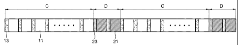
Referring to FIGs. 2 and 3, an information storage medium
according to an embodiment of the present invention includes user data
areas C in which user data is recorded and additional data areas D
located before and/or after the user data areas C. The information
storage medium may be a recordable information storage medium or a
read-only information storage medium.
Each of the user data areas C contains a plurality of user data 11
separated by a plurality of first sync patterns 13. According to an aspect
3
CA 02503372 2005-04-21
WO 2004/053870 PCT/KR2003/002627
of the invention, the user data areas C include error correcting code
(ECC) recording units.
Each of the additional data areas D contains a plurality of
additional data 21 separated by a plurality of second sync patterns 23.
Here, as will be explained later, the first sync patterns 13 have
modulation codes corresponding to sync numbers shown in Tables 1 and
2 and are formed by combining predetermined selected sync numbers.
The second sync patterns 23 are formed of predetermined type of
patterns denoted by reference numerals 23a and 23b according to the
same method as the plurality of first sync patterns 13.
According to an aspect of the invention, the second sync patterns
23 are different from the first sync patterns 13. In other words, the
second sync patterns 23 are formed of patterns which are not used as
the first sync patterns 13. By forming the second sync patterns 23 to be
different from the first sync patterns 13, a reproducing system such as
that shown in FIG. 4 can manage the additional data areas D by being
able to differentiate the additional data areas D, with certainty, from the
user data areas C.
The number of second sync patterns 23 depends on the length of
the additional data areas D. It is preferable, but not required, that the
second sync patterns 23 are arranged at equal intervals in order to
increase an effective additional data efficiency of the additional data
areas D. In addition, sync data can be easily restored during reproducing.
While not required, according to an aspect of the invention, the
size of each of the plurality of user data 11 in the user data areas C is
equal to a size of each of the plurality of additional data 21 in the
additional data areas D. This structure can be realized by adjusting the
positions of the second sync patterns 23.
It is preferable, but not required, that the entire size of additional
data 21 in the additional data areas D be integer multiples of the size d1
of user data 11 recorded between two adjacent first sync patterns 13a
and 13b. In other words, referring to FIG. 2, the size d2 of additional data
21 recorded between two adjacent second sync patterns 23a and 23b is
4
CA 02503372 2005-04-21
WO 2004/053870 PCT/KR2003/002627
equal to the size d1 of the user data 11 recorded between first sync
patterns 13a, 13b, and the additional data 21 are recorded in two parts of
each of the additional data areas D. Thus, the total size of the additional
data 21 is an integer multiple of (i.e., is twice the size of) the size d1 of
the user data 11. As a result, since sync signals are detected at regular
intervals in all areas during reproducing of data, it is advantageous to
restore the sync signals.
The structure of the information storage medium using a run-
length-limited (RLL) (d, k) code will be described below. The RLL code
indicates how many bits of value "0" exist between two bits of value "1".
Thus, the RLL (d, k) code represents that the minimum number d and the
maximum number k of bits of value "0" between two bits of value "1 ",
respectively.
In the structure using the RLL (d, K) code, the first sync patterns
13 generally include sync bodies that do not satisfy the RLL (d, k) code
and sync identifications (IDs) that satisfy the RLL (d, k) code. In other
words, the sync bodies have a run length k + i when i is an integer that is
greater than or equal to 1". The sync IN contain different patterns to
distinguish N different sync patterns.
The second sync patterns 23 include sync bodies that do not
satisfy the RLL (d, k) code and sync IN that satisfy the RLL (d, k) code.
Here, the sync IN contain different patterns to distinguish N different
sync patterns.
FIG. 3 illustrates an embodiment of the data structure of an
information storage medium including additional data areas D each
having two additional data frames. Sync bodies and sync IN of the
information storage medium having the above data structure are shown
in Tables 1 and 2 below.
As can be seen in Table 1, a RLL (1,7) code is used. Each sync
body has 18 bits, and each sync ID has 6 bits. The user data area C
includes 9 user data frames for sync data, and the additional data area D
includes two user data frames for sync data.
CA 02503372 2005-04-21
WO 2004/053870 PCT/KR2003/002627
Table 1
Sync No. 18-Bit Sync Body 6-Bit Sync ID Remark
0 001 001 010 000 000 010 000 001
1 001 001 010 000 000 010 010 010
2 001 001 010 000 000 010 101 000
3 001 001 010 000 000 010 100 001
User Data Area
4 001 001 010 000 000 010 000 100
001 001 010 000 000 010 001 001 Sync Data
6 001 001 010 000 000 010 010 101
7 001 001 010 000 000 010 010 000
8 001 001 010 000 000 010 101 010
9 001 001 010 000 000 010 100 101 Additional Data
001 001 010 000 000 010 101 001 Area Sync Data
As can be seen in Table 2, a RLL (2,10) code is used. Each sync
body has 22 bits, and each sync ID has 10 bits. The user data area C
includes 7 user'data frames for sync data, and the additional data area D
includes 2 user data frames for sync data.
Table 2
Sync No. 22-Bit Sync Body 10-Bit Sync ID Remark
0 100 001 000 000 000 000 010 0 010 001 000 1
1 100 001 000 000 000 000 010 0 0001001001
2 100 001 000 000 000 000 010 0 010 000 010 0 User Data
3 100 001 000 000 000 000 010 0 001 0000000 Area
4 100 001 000 000 000 000 010 0 1001001000 Sync Data
5 100 001 000 000 000 000 010 0 010 000 100 0
6 100001 0000000000000100 0000100000
7 100 001 000 000 000 000 010 0 010 001 000 1
6
CA 02503372 2005-04-21
WO 2004/053870 PCT/KR2003/002627
8 100 001 000 000 000 000 010 0 0100100100 Additional
Data Area
Sync Data
As shown in Tables I and 2, the sync data in the additional data D
area has different patterns as compared to the sync data in the user data
area C. In other words, the sync IDs of the second sync patterns 23
have sync patterns not used as the first sync patterns 13. Therefore, the
additional data areas D can be managed and can be distinctly
differentiated from the user data areas C.
A method of recording information on and/or reproducing
information from the information storage medium having the above-
described structure will be described. As shown in FIG. 2, the user data
areas C including basic ECC recording blocks and the additional data
areas D located before and/or after the user data areas C are prepared in
the information storage medium. Next, the second sync patterns 23 used
in the additional data areas D are formed differently from the first sync
patterns 13 used in the user data areas C.
Here, the second sync patterns 23 are plural and arranged at
equal intervals. It is preferable, but not required, that the second sync
patterns 23 are arranged in the additional data areas D so that the size of
each of user data 11 in the user data areas C is equal to the size of each
of additional data 21 in the additional data areas D.
Sync data in the additional data areas D contains sync bodies
having second sync patterns that do not comply with the RLL (d, k) code
and sync IDs having second sync patterns that comply with the RLL (d, k)
code. The total size of additional data 21 in the additional data areas D is
an integer multiple of the size of user data 11 recorded between two first
sync patterns 13a and 13 b.
While not specifically so limited, it is understood that the
information storage medium can include the CD-Rs, CD-RWs, DVD-RWs,
DVD-RAMs, DVD+RWs, as well as next generation high definition DVDs,
7
CA 02503372 2005-04-21
WO 2004/053870 PCT/KR2003/002627
such as Blu-ray discs, Advanced Optical Discs (AODs) and other optical
storage media not listed above and/or to be developed.
FIG. 4 is a block diagram of a recording and/or reproducing
apparatus according to an embodiment of the present invention.
Referring to FIG. 4, the recording and/or reproducing apparatus includes
a recording/reading unit 1001, a controller 1002, and a memory 1003.
The recording/reading unit 1001 records data on a disc 1000, which is an
embodiment of an information storage medium of the present invention,
and reads the data from the disc 1000. The controller 1002 records and
reproduces the user data 11 and the additional data 21 according to the
present invention as set forth above in relation to FIGs. 2 and 3.
While not required in all aspects, it is understood that the controller
1002 can be a computer implementing the method using a computer
program encoded on a computer readable medium. The computer can
be implemented as a chip having firmware, or can be a general or special
purpose computer programmable to perform the method.
In addition, it is understood that, in order to achieve a recording
capacity of several dozen gigabytes, the recording/reading unit 1001
could include a low wavelength, high numerical aperture type unit usable
to record dozens of gigabytes of data on the disc 1000. Examples of
such units include, but are not limited to, those units using light
wavelengths of 405 nm and having numerical apertures of 0.85, those
units compatible with Blu-ray discs, and/or those units compatible with
Advanced Optical Discs (AOD).
While the present invention has been particularly shown and
described with reference to exemplary embodiments thereof, it will be
understood by those of ordinary skill in the art that various changes in
form and details may be made therein without departing from the spirit
and scope of the present invention as defined by the following claims and
equivalents thereof.
Industrial Applicability
8
CA 02503372 2005-04-21
WO 2004/053870 PCT/K1R2003/002627
As described above, an information storage medium and a
method of recording information thereon and/or reproducing information
therefrom according to the present invention can maintain consistency
with the formats of different types of recordable information storage
media and have reproduction compatibility in a drive.
Also, since sync patterns used in user data areas can be formed
differently from sync patterns used in additional data areas, the additional
data areas can be further efficiently separated from the user data areas.
Furthermore, by uniformly maintaining the length of data recorded
in the user data areas and the additional data areas, sync signals can be
detected at regular intervals in all areas during reproducing of data. Thus,
it is advantageous to restore the sync signals.
9