Note: Descriptions are shown in the official language in which they were submitted.
CA 02508086 2005-05-20
-1-
Title: ROCKER RAILS
Field of the invention
This invention relates generally to chairs and, more specifically,
to rocking chairs.
Backcround of the invention
Maintaining the attention span of students, especially young
students, in a classroom situation has always been a difficult task. Providing
the student with a desk and desk chair which is comfortable and provides
good ergonomics throughout the many long hours in a typical school day is
increasingly understood to be a critical factor in maintaining the student's
attention span.
Also, the dramatic increase in student hours spent in high-
intensity computing has created a need for ergonomically sound classroom
furniture designed for such activities. Such ergonomically sound classroom
furniture tends to prevent distracting discomfort and reduces the risk of
injuries associated with long-term exposure to poor ergonomics.
Accordingly, there is a need for a student desk chair which is
comfortable throughout the long hours in a typical school day, especially
where such long hours may include work at a computer terminal and
keyboard.
Such a desk chair must, in addition to being comfortable, must
be relatively inexpensive to manufacture, have a relatively small foot print,
be
easy and safe for ingress and egress and be conveniently storable above the
floor (to facility cleaning of the classroom).
CA 02508086 2005-05-20
_2_
Summary of the invention
The invention satisfies this need. The invention is a rocking chair and
a rocking chair/classroom desk combination. In one embodiment of the
invention, the rocking chair comprises: (a) a seating surface; (b) a backrest
disposed above the seating surface; and (c) a support carriage comprising a
left side reverse cantilevered rocker rail and an opposed right side reverse
cantilevered rocker rail, both rocker rails being disposed generally parallel
to
the longitudinal axis of the seating surface, the support carriage being
adapted to support the seating surface above the floor.
In another embodiment, the rocking chair comprises: (a) a
seating surface having a horizontal longitudinal axis, a forward edge which
terminates at a vertical forward edge seating surface plane disposed generally
perpendicular to the longitudinal axis of the seating surface, a left side
edge
which terminates at a vertical left side seating surface plane disposed
generally parallel with the longitudinal axis of the seating surface and a
right
side edge which terminates at a vertical right side seating surface plane
disposed generally parallel with the longitudinal axis of the seating surface;
(b)
a backrest disposed above the seating surface, the backrest having an upper
edge which terminates at a vertical backrest plane disposed generally
perpendicular to the longitudinal axis of the seating surface; and (c) a
support
carriage having a left side rocker rail and an opposed right side rocker rail,
the
support carriage being adapted to support the seating surface at an elevation
above a floor, the pair of rocker rails being generally parallel to the
longitudinal axis of the seating surface, each rocker rail having a forward
most
portion, a rearward most portion and a central portion, the forward most
portion extending forwardly no more than about 3 inches beyond the forward
edge seating surface plane, the rearward most portion extending rearwardly
no more than about 1 inch beyond the backrest plane, the left side rocker rail
extending laterally no more than about 1 inch beyond the left side seating
surface plane and the right side rocker rail extending laterally no more than
about 1 inch beyond the right side seating surface plane, the central portions
of both rocker rails being at least about 20 inches in length and having lower
CA 02508086 2005-05-20
-3-
surfaces with identical curvatures, both curvatures having one or more
degrees of curvature, none of which is greater than about 70 degrees.
Brief description of the drawincts
These and other features, aspects and advantages of the present invention
will become better understood with reference to the following description,
appended claims and accompanying drawings where:
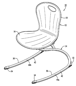
Figure 1 is a perspective view of a rocking chair having features of the
invention;
Figure 2 is a front view of the rocking chair illustrated in Figure 1;
Figure 3 is a side view of a classroom chair and desk combination
having features of the invention, including a side view of the rocking chair
illustrated in Figure 1;
Figure 4 is a top view of the rocking chair illustrated in Figure 1;
Figure 5 is a bottom view of the rocking chair illustrated in Figure 1;
Figure 6 is a rear view of the rocking chair illustrated in Figure 1; and
Figure 7 is a second perspective view of the rocking chair illustrated in
Figure 1, showing the underside of the rocking chair.
Detailed description of the invention
The following discussion describes in detail one embodiment of the
invention and several variations of that embodiment. This discussion should
not be construed, however, as limiting the invention to those particular
CA 02508086 2005-05-20
-4-
embodiments. Practitioners skilled in the art will recognize numerous other
embodiments as well.
The invention is a rocking chair 10 having unique characteristics
which make it suitable as a classroom chair.
As illustrated in the drawings, a typical rocking chair 10 of the
invention comprises a seating assembly 12 mounted on a support carriage
14. The seating assembly 12 comprises a generally horizontal seating
surface 16 and a generally vertical backrest 18 disposed above the seating
surface 16. The seating assembly 12 is preferably contoured to conform to
the body of the user for whom the rocking chair 10 is designed.
The seating assembly 12 can be made from a variety of
materials, including metals, woods and plastics. Plastic materials, such as
polypropylene, have been found to be suitable for use in the seating assembly
12.
The seating surface 16 has a horizontal longitudinal axis 20 and
a forward edge 22 which terminates at a vertical forward edge seating surface
plane 24 which is disposed generally perpendicular to the longitudinal axis 20
of the seating surface 16. The seating surface 16 further comprises (i) a left
side edge 26 which terminates at a vertical left side seating surface plane 28
which is generally parallel to the longitudinal axis 20 of the seating surface
16
and (ii) a right side edge 30 which terminates at a vertical right side
seating
surface plane 32 which is generally parallel to the longitudinal axis 20 of
the
seating surface 16.
The backrest 18 has an upper edge 34 which terminates at a
vertical backrest plane 36 which is disposed generally perpendicular to the
longitudinal axis 20 of the seating surface 16. An aperture 38 can be provided
in the backrest 18 to provide a hand-hold for the convenient lifting of the
rocking chair 10.
In the embodiment illustrated in the drawings, a plurality of
parallel reenforcing ribs 40 are provided on both the rear side of the
backrest
18 and the underside of the seating surface 16 to provide additional rigidity.
CA 02508086 2005-05-20
-5-
The seating assembly 12 can be provided in a plurality of
assembled parts or, as illustrated in the drawings, as an integral unit.
The seating assembly 12 is attached to the support carriage 14
such that the seating surface 16 is supported at an appropriate height above a
floor. The support carriage 14 can have any number of configurations. In the
embodiment illustrated in the drawings, the support carriage 14 is comprised
of rolled steel tubing.
The support carriage 14 comprises a pair of opposed generally
parallel rocker rails 42. Preferably, as illustrated in the drawings, the
rocker
rails 42 comprise a left side reverse cantilevered rocker rail 44a and an
opposed right side reversed cantilevered rocker rail 44b. The use of
cantilevered rocker rails 42 provide the support carriage 14 with a degree of
flexure not found where the rocker rails 42 are supported by linear struts.
The use of reverse cantilevered rocker rails 42 provides
additional advantages over conventional cantilevered rocker rails 42. The
forwardmost portions 46 of the rocker rails 42 in embodiments having
reversed cantilevered rocker rails 42 do not protrude as far forward and are
not disposed as far above the floor as are the forwardmost portions 46 of the
cantilevered rocker rails 42 which are not reversed in design. Accordingly,
the
use of reverse cantilevered rocker rails 42 facilitate the safe and easy
ingress
and egress by the user and facilitate the construction of a classroom rocking
chair 10 having a reduced footprint.
Rocking chairs 10 having minimized footprints are very
important in classroom situations to efficiently make use of the limited space
available within the classroom and to safely and efficiently retain a large
number of students within the classroom. A smaller foot print also reduces
the risk of tripping over the rocker rails 42. Thus, it is preferably that the
forwardmost portion 46 extends forwardly no more than about 3 inches
beyond the forward edge seating surtace plane 24, the rearwardmost portion
48 extends rearwardly no more than about 1 inch beyond the backrest plane
36, the left side rocker cantilevered rocker rail 44a extends laterally no
more
than about 1 inch beyond the left side seating surface plane 28 and the right
CA 02508086 2005-05-20
-6-
side reverse cantilevered rocker rail 44b extends laterally no more than about
1 inch beyond the right side seating surface plane 32.
An additional advantage of using reverse cantilevered rocker
rails 42 is that the use of reverse cantilevered rocker rails 42 encourages
both
relaxed and attentive seating. All rocker rails 42 allow the user to lean
back,
tipping the seat angle rearward into a relaxed position. Traditional
cantilevered rocker rails 42 allow the rocking chairs 10 to emphasize this
because their frame-flex naturally rotates the seating surface 16 further
back.
However, with reverse cantilevered rocker rails 42, the seating surface 16
angle tends to tip forward during the front portion of the rocker rails'
travel (as
the backrest 18 flexes into a more closed position), particularly when the
user's weight and sitting position shifts slightly forward on the seating
surface
16 (as when the user is operating a keyboard) which allows better back
support, permits the pelvis to rotate forward for better ergonomics and
comfort
during focused work (by encouraging proper reversed curvature of the lumbar
spine) and opens up the leg-body angle for better blood flow to the legs and
feet.
The use of reverse cantilevered rocker rails 42 also provides the
advantage of allowing the rocking chair 10 to be simply and easily stored
above the floor (such as for cleaning the floor) by resting the underside of
the
seating surface 16 on the top of the desk 58 while sliding the rocker rails 42
immediately below the desktop.
The support carriage 14 and the rocker rails 42 are configured
and constructed of materials so that the amount of spring in the support
carriage 14 when in use by a user is not excessive and is not too stiff. In
one
embodiment, the rocker rails 42 are made of 12-gage (0.1046) steel tube with
a nominal 1-inch outside diameter.
The rocker rails 42 each have a forwardmost portion 46, a
rearwardmost portion 48 and a central portion 50. Typically, the central
portion 50 of both rocker rails 42 is at least about 20 inches in length and
have lower surfaces with identical curvatures. Typically, the curvature of
both
rocker rails 42 have a single degree of curvature between about 50 degrees
CA 02508086 2005-05-20
-7-
and about 70 degrees, preferably between about 55 degrees and about 65
degrees. In one embodiment, the radius of the two rocker rails 42 is 60.17
degrees.
Preferably, the forward motion of the rocking chair 10 and the
rearward motion of the rocking chair 10 are carefully controlled so as to
provide sufficient forward and rearward motion, while preventing excessive
forward and rearward motion. In the embodiment illustrated in the drawings,
the furthest forward motion of the rocking chair 10 is about 8.5 degrees from
its at-rest position. The furthest rearward motion of the rocking chair 10 is
about 7 degrees from the at-rest position.
Typically, the rearwardmost portion 48 of both rocker rails 42
comprises a rocker stop 52 to effectively prevent rearward rocking motion of
the rocking chair 10. The rocker stop can be made from a resilient material.
Typically, the forwardmost portions 46 of both rockers 10 are
covered with a cap 54 made of a resilient material.
The invention is also a classroom desk and chair combination
56 comprising (i) a student desk 58 having an elevated, generally horizontal
work surface 60 and an open space 62 defined below the work surface 60
and (ii) a rocking chair 10 as described above. Typically, the work surface 60
defines a work surface area of at least about 50 square inches, most typically
of at least about 225 square inches, such as between about 500 square
inches and about 1000 square inches. In the desk and chair combination 56,
the rocking chair 10 is sized and dimensioned to allow the forward portion of
the rocking chair 10 to be positioned within the open space 62 below the work
surface 60. The work surface 60 is disposed at an elevation between about
10 inches and about 15 inches above the elevation of the seating surface 16
of the rocking chair 10. Such a design of a classroom desk and chair
combination 56 allow a student to comfortably sit within the rocking chair 10
and work at the work surface 60. Such desk and chair combination 56 are
especially suited for comfortably retaining students within a classroom
situation for many hours at a time, even where the students are working at
CA 02508086 2005-05-20
_ 8 _
computer terminals disposed on top of the work surfaces 60, for example,
laptop computer terminals placed upon the work surfaces 60.
The rocking chair 10 of the invention provides both good
ergonomics and comfort in a product that is also attractive and fun to use.
Such a rocking chair 10 will provide students with positive feelings about
their
school and about their classroom environment. Such positive feelings are
recognized by educators to be critical factors in the improvement of a
student's academic performance.
Having thus described the invention, it should be apparent that
numerous structural modifications and adaptations may be resorted to without
departing from the scope and fair meaning of the instant invention as set
forth
hereinabove.