Note: Descriptions are shown in the official language in which they were submitted.
CA 02509740 2005-06-09
BACKGROUND OF THE INVENTION
(1) Field of the Invention
[0001]The present invention relates to a bioreactor including one or more
features
that improve bioreactor liquid infiltration and gas recovery. The bioreactor
of this
invention described creates an extremely large area for infiltration and gas
recovery.
It further eliminates the vertical gas wells and replaces them, in part, with
self
draining angular wells in the infiltration area. The surface area for gas
recovery
based on the porous media supplied is an order of magnitude greater than the
vertical well based gas recovery systems.
to (2) Description of the Art
[0002] About 15 years ago, landfill owners began using leachate recirculation
as a
remediation method. The dominant techniques have been to inject leachate into
landfills using horizontal leachate piping, vertical wells, or applying
leachate to the
working landfill face surface. Distribution of the liquid over a large area
has always
been concern. Often landfill material surrounding the leachate injection sites
become
clogged with slime, fines.or calcium/iron complexes. Additionally, the gas
recovery
wells, that are typically vertical, often filled with water and or leachate.
These
flooded wells resulted in poor gas collection and the need to place expensive
liquid
pumps in the gas well casings.
[0003] Differential landfill settlement complicates compliance with the
environmental
regulations related to gas and simultaneously increases maintenance costs
dramatically. Since the 1980s' over 90% of the landfill gas recovery systems
in the
United States and Canada use vertical gas extraction wells. Standard practice
is to
-2-
CA 02509740 2005-06-09
drill a 30" to 36" diameter well and insert a 6" to 8" diameter gas pipe and
then fill
the boring with stone. This system was designed for landfills that do not
apply large
volumes of liquid, such as leachate, to landfills. Over the years with the
development
of leachate recirculation, air operated pumps have become standard in wet
landfills.
This has resulted in a high maintenance costs. Along-with these pumps, many
landfills are increasing the density of the gas recovery wells.
[0004]Advances in landfill remediation have been made recently. U.S. Patent
No.
6,742,962 discloses a horizontal infiltration and gas recovery system. The
system is
designed to eliminate some of these problems with gas recovery in wet landfill
io systems. While the system is an improvement over vertical gas recovery
systems it
still requires liquid pumps associated with the gas recovery wells and the
system is
subject to oxygen intrusion if the cover soil is not properly compacted.
Another issue
with this system is the potential for limited liquid coverage due to non-
homogeneous
waste placement and chemical blinding of the trenches. U.S. Patent No.
6,283,676
discloses systems that employ short-term compressed air addition into a
landfill in
order to initiate aerobic bacterial growth and degradation.
[0005] Despite these advances, there remain problems with existing leachate
recirculation and/or landfill gas recovery systems including (1) the continued
dependency on vertical gas wells; (2). The requirement to pump liquids out of
vertical gas wells as the infiltration field became saturated; (3)
historically, infiltration
systems do not allow for surface application initially followed by deep
infiltration and
the landfill is filled for the apparatus is covered; (4) the need for a system
that would
allow for infiltration and gas recovery simultaneously. Furthermore, there is
a need
-3-
CA 02509740 2005-06-09
to be able-to drain liquids from the gas collection system and improve gas
recovery
for the saturated infiltration field. Additionally gas systems in older wet
landfills are
prone to maintenance issues related to settling of the gas system. Vertical
wells
sheer off and crush and the interconnecting horizontal gas headers often water
out.
-
-4-
CA 02509740 2005-06-09
SUMMARY OF THE INVENTION
[0006] In one aspect, this invention is a bioreactor comprising a compostable
material and at least one bioreactor located in the compostable material
wherein the
bioreactor cell further comprises: (i) a central core including liquid
infiltration piping;
(ii) a porous gas recovery material including at least one gas collection
pipe; and (iii)
a berm separating the central core from the porous gas recovery material.
[0007] In another aspect, this invention is a method for constructing a
landfill
bioreactor comprising the steps of: (a) placing a layer of compostable
material in a
landfill; (b) locating a bioreactor comprising (i) a central core including
liquid
io infiltration piping; (ii) a porous gas recovery material including at least
one gas
collection pipe; and (iii) a berm separating the central core from the porous
gas
recovery material on top of the layer of compostable material; and (c) placing
a layer
of material over the bioreactor.
[0008] In yet another aspect, this invention is a landfill including at least
one
is bioreactor comprising a central core including liquid infiltration piping;
(ii) a porous
gas recovery material including at least one gas collection pipe; and (iii) a
berm
separating the central core from the porous gas recovery material on top of
the layer
of compostable material.
-5-
CA 02509740 2005-06-09
Description Of The Figures
[0009] Figure 1 is a top view of an embodiment of an infiltration/gas recovery
bioreactor of this invention;
[0010] Figure 2 is a side view of a landfill including a plurality of
bioreactor
s embodiments of this invention wherein the bioreactors are located on the
same or
different horizontal planes;
[0011] Figure 3 is a side cut-away view, along line A-A of the
infiltration/gas recovery
bioreactor embodiment of Figure 1;
[0012] Figure 4 is a side cut-away view, along line B-B of the
infiltration/gas recovery
io bioreactor embodiment of Figure 1;
[0013] Figure 5 is a view of an infiltration pipe system useful in
infiltration/gas
recovery bioreactor embodiments of this invention;
[0014] Figure 6 is a close up view of the portion of the infiltration pipe
system
designated by the letter C in Figure 5;
15 [0015] Figure 7 is a close up view of the portion of the infiltration pipe
system
designated by the letter D in Figure 5;
[0016] Figure 8 is an overhead view of a landfill including a bioreactor
embodiment
of this invention: and
[0017] Figure 9 is an overhead view of a stand-alone bioreactor embodiment of
this
20 invention.
-6-
CA 02509740 2005-06-09
DESCRIPTION OF THE CURRENT EMBODIMENT
[0018]The present invention relates to a bioreactor including one or more
features
that improve bioreactor liquid infiltration and gas recovery. The bioreactor
of this
invention creates an extremely large area for infiltration and gas recovery.
It further
eliminates the vertical gas wells and replaces them, in part, with self
draining angular
wells in the infiltration area. The surface area for gas recovery based on the
porous
media supplied is an order of magnitude greater than the vertical well based
gas
recovery systems.
[0019]The present invention solves one or more of the following problems
existing in
io prior art landfill liquid infiltration systems - with or without gas
recovery. Specifically
this invention does one or more the following or has one or more of the
following
features:
= eliminates vertical wells and their requisite dewatering pumps.
= moves horizontal gas headers from the interior of the landfill to the outer
slopes where they can be easily maintained and drained;
= provides inner wells with improved drainage of the gas collection piping
system by angling the gas collection pipes to facilitate automatic drainage
back into the wet mass;
= may iriclude an internal dam between the infiltration area and the gas
collection area that forces moisture downward and away from the landfill
edges;
-7-
CA 02509740 2007-07-12
= may include a geotextile such as Geonet or felt to inhibit liquid clogging
of the
gas collection area and to prevent solid waste fines from filling voids in the
porous gas recovery material;
= may include the placement of a 10 to 30 mil plastic sheet below the long
term
or permanent cover of a landfill to improve surface gas emissions ad to make
it easier to comply with New Source Pollutions Standards (NSPS) when a
=bioreactor of this invention is installed at the last lift (the highest lift
vertically)
of a landf II;
= before eacfi landfill field, including one or more bioreactor is covered,
the
infiltration center of each bioreactor can be used to apply liquids to the
exposed landfill surface;
= the horizontal gas recovery pipes may be strategically located to allow for
convenient vacuum pressure adjustment on the interior of the landfill;
= the landfill surface may be sloped to one end to allows for gravity drainage
in
the event of flooding;
= The piping for gas recovery may be sloped so that the lowest end of the gas
recovery piping can be used as a liquid drain;
= the soil or clay edge of the landfill may be inwardly sloped at the surface
of
this bioreactor systems of this invention to inhibit_gas and leachate
breakouts
or leaks;
= the infiltration piping and horizontal gas recovery piping can optionally be
used for air addition.
-s-
CA 02509740 2005-06-09
[0020] One embodiment of a bioreactor system of this invention is shown in the
Figures. This invention will be described with reference to the bioreactor
system
shown in Figures 1-9. However, this description of an exemplary embodiment is
not
intended to limit the scope of the claims in any manner.
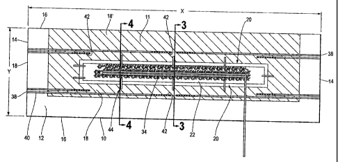
[0021] Figure 1 is a top view of a bioreactor 10 of this-invention associated
with a
landfill slope without a cover material. Figure 9 is an overhead view of a
stand-alone
bioreactor embodiment 10 of this invention. In most instances, the bioreactors
of
this invention will be installed as lifts are being added to landfills. Once a
lift is
complete, a bioreactor system of this invention will be installed and then
addition
io compostable material such as municipal solid waste will be placed over the
bioreactor systems of this invention. If the bioreactor system is installed on
top of
the last landfill lift, then the bioreactor system can be covered with a cap
material as
discussed below. Alternatively, the bioreactor systems of this invention may
be
stand alone bioreactors that are constructed independently from a landfill in
order to
remediate compostable materials including, but not limited to municipal solid
waste,
yard waste, agricultural waste, and so forth as well as combinations of
different
types of waste materials. For purposes of this invention, the term compostable
material should be broadly interpreted to include any liquid or solid material
that can
act as a food source for aerobic and/or anaerobic microorganisms under aerobic
2o and/or anaerobic compositing conditions.
[0022] Bioreactor 10 shown in Figure 1 can have any length (X) with a total
length of
up to 2000 feet or more being possible. Moreover the landfill can have a width
(Y) of
any useful length with a maximum length exceeding 2000 feet. For purposes of
this
-9-
CA 02509740 2005-06-09
invention, -the term "length" and "width" and their associated definitions may
be
switched. For example, if the landfill is long and narrow, the landfill width
may be
longer than the length. Generally, however, the dimension of the landfill that
is
parallel to the gas withdrawn and/or liquid infiltration piping will be the
"length"
s dimension of bioreactor 10. The length to width ratio is not critical.
However, it is
preferred that the length to width ratio be at least 2:1 and at most about
5:1.
[0023] In Figure 1, a confining layer 12 is located at the ends 14 and sides
16 of the
bioreactor 10. When bioreactor 10 is associated with a landfill, then
confining layer
12 will be associated only with the ends and sides of the bioreactor that lie
on the
1o outside perimeter of the landfill. In this instance, inner side 11 of
bioreactor 10
includes a porous material layer 18' contiguous with the sidewall or slope of
an
adjoining bioreactor cell. A typical width of confining layer 12 is from about
50 feet to
about 60 feet. However, the width of confining layer 12 may range from about
20
feet to about 80 feet and will still be useful.
15 [0024] Inside confining layer 12 is a porous gas recovery layer 18 such as
tire chips,
gravel, glass cullet, selected (low dust and drywall content) construction and
demolition debris, or a double-sided geocomposite manufactured by GSE Lining
Technology, Inc. Double-sided geocomposite is a sheet material consisting of a
sheet of netting material sandwiched between two layers of felt material. The
--~.-
2o double-sided geocomposite material promotes the lateral transmission of
water that
permeates into the mesh center of the material. Porous gas recovery layer 18
may
be covered with a geotextile sheet 19 (shown in Figure 3) to further protect
the gas
recovery piping from liquid infiltration and to protect gas recovery layer 18
from
-io-
CA 02509740 2005-06-09
becoming-fouled and plugged with compostable material fines. Porous gas
recovery
layer 18 may have a thickness ranging from about 1 inch to about 24 inches or
more
with a thickness of from about 6 inches to about 18 inches being preferred.
Porous
gas recovery layer 18 defines a gas collection volume in which gas collection
piping
s is preferably located. If Porous gas recovery layer 1$. is a double-sided
geocomposite, then the double-sided geocomposite sheet will be located above
the
gas collection piping.
[0025] Porous gas recovery layer 18 will vary in length depending upon the
length of
the bioreactor. A typical porous material layer will have a width of from
about 60 feet
io to about 100 feet wide or greater. The ends of the porous material layer
are typically
about 40 feet to about 80 feet wide. If the landfill cell is greater than 400'
to 500' in
width, then more that one bioreactor can be placed laterally in the cells so
liquids
can be distributed across with width of the cell. Moreover, porous gas
recovery layer
18 may be continuous - running the entire length and width of the bioreactor.
Or
15 porous gas recovery layer 18 may be discontinuous in which case porous
material
layer should be constructed in locations that essentially correspond to the
locations
where the gas recovery piping is perforated.
[0026] Next a berm 20 is placed inside the porous gas recovery layer 18. The
purpose of berm 20 is to force liquids downward to inhibit liquids from
entering the
20 gas collection system. Berm 20 is typically made of a material selected
from soil or
day. However, the material selected may be any material that is capable of
containing a liquid and/or creating a liquid barrier between central core 22
of
bioreactor 10 and porous gas recovery layer 18. In this regard, the preferred
soil or
-11-
CA 02509740 2005-06-09
clay material used in berm 20 can be substituted with a special waste material
such
as fly ash, asphalt, contaminated soil, a soil like material or waste
material, or with a
synthetic sheet by itself or in combination with the soil or clay or special
waste
material in order to decrease the area or thickness of berm 20. If a synthetic
sheet
is used for berm 20, then the synthetic sheet may be a single layer sheet or
it may
preferably be an impervious synthetic material sheet on which a material such
as
sand, dirt, or the like has been placed on a portion of the sheet after which
the
uncovered portion of the sheet is folded over the top of the material such
that the
edges of the synthetic material sheet are essentially united.
1o [0027] Berm 20 may be a continuous berm or discontinuous with a continuous
berm
being preferred. In Figure 1 a continuous berm surrounds a liquid infiltration
area
that has a central core 22 that is preferably several feet wide. Central core
22 may
be comprised of any liquid permeable material including but not limited to
liquid
permeable compostable material, stone, tire chips, glass cullet, selected
is construction and demolition debris, or any other similar liquid permeable
materials.
Central core 22 may be as narrow as about 10 feet and as wide as about 500
feet or
wider. Central core 22 will typically be from about 40 feet to about 80 feet
wide and
it is typically terminated from about 25 to about 200 feet and more preferably
from
about 100 feet to about 150 feet from the edge of the bioreactor or landfill.
2o [0028] Figure 2 is a side view of a landfill including a plurality of
bioreactors 10 of this
invention wherein the bioreactors are located on the same or different
horizontal
planes. When bioreactors are located on different horizontal planes, then they
may
be offset by a distance Z wherein Z may be from 10 feet to 100 feet or more
but is
-12-
CA 02509740 2005-06-09
preferably-about 15 feet to about 25 feet. When a bioreactor 10 is located in
the
top-most lift of a landfill, then it is preferred that the bioreactor is
covered with a
compostable material layer 24 having a depth of from about 5 feet to about 50
feet
and preferably from about 5 feet to 20 feet. Compostable material layer 24
forms a
buffer zone between the top-most bioreactor 10' and 1he landfiil surface that
inhibits
oxygen infiltration into the bioreactor, and/or that allows for better
landfill surface
grading. Bioreactors located at the top-most lift of a landfill may also be
covered
with a cap material 26 that is preferably selected from soil or clay. The
optional cap
material will generally have a thickness of from about 1 foot to 10 feet or
more with a
io thickness of from 2 feet to 5 feet being more preferred. An optional
barrier material
layer 28 may be located between cap material 26 and bioreactor 10 and
preferably
between cap material 26 and compostable material layer 24. Barrier material
layer
28 may be any material that inhibits water infiltration into bioreactor 10. An
example
of a useful barrier material layer 28 would include a plastic sheet material
having a
thickness of from about 10 to about 40 mils.
[0029] If a barrier material layer 28 is used in conjunction with one or more
bioreactors located in a landfill, then barrier material layer 28 may cover
one to all of
the plurality of bioreactors. It is preferred however that barrier material
layer 28
covers only those bioreactors 10 that are not located below a landfill slope
30 as
2o shown in Figure 2. Moreover, slope 30 should be great enough to allow rain
water to
run off of the landfill without causing flooding. A slope 30 having a grade of
from 1:1
to about 10:1 or more would be useful with slopes ranging from about 2.5:1 to
5.6:1
being more preferred.
-13-
CA 02509740 2005-06-09
[0030] Figure 3 is a cross section along line "A" in Figure 1. This cross
section
shows some of the major infrastructure of bioreactor 10. However, the Figure 3
cross-section does not show gas extraction piping, infiltration piping, and in
situ well
pipes. These features are, however, shown in the Figure 4 cross-section and
discussed below. As discussed above, ends 14 and sides 16 of bioreactor 10
include a confining layer 12 for example, soil or clay that is preferably 12
inches to
18 inches deep but that may be deeper or shallower as required. According to
Figure 3, confining layer 12 is preferably sloped towards central core 22 of
bioreactor 10. Inside confining layer 12 is a porous gas recovery layer 18
that
io optionally covered with geotextile sheet 19 which includes felt.
[0031] Inside porous gas recovery layer 18 is berm 20. Berm 20 will typically
be
formed of soil and it may have a width of from about 6 inches to about 20 feet
Berm 20 is more typically from about 6 feet to about 15 feet wide with about
10 feet
wide being most preferred. However, berm 20 can be less than 10 feet wide.
[0032] Inside berm 20 is a central core 22 of porous material. Inside central
core 22
is a central porous material layer 32. Central porous material layer 32 can be
rock,
gravel, tire chips, wood chips, selected construction and demolition debris,
glass
cullet or any combination of materials that form a porous layer. According to
Figures
3-4, liquid infiltration piping 34 is located within central porous material
layer 32.
--_~-
2o Liquid infiltration piping 34 includes a plurality of perforations 36 and
is preferably
located in central porous material layer 32 such that essentially every
perforation 36
is covered by central porous material layer 32.
-14-
CA 02509740 2005-06-09
[0033] In the center of the inner most rectangle of Figure 3 is central porous
material
layer 32 in which liquid infiltration piping 34 is located. In a preferred
embodiment,
liquid infiltration piping 34 is a 3" to 6" diameter HDPE perforated double
pipe
system as shown in Figure 5. Central porous material layer 32 is preferably a
coarse material such as non-calcareous stone or other non-compressible inert
materials not affected by organic acids A preferred coarse material is a
coarse rock
and more preferably, a coarse rock that is non-calcareous in nature so as not
to add
in precipitation of iron, calcium and magnesium complexes. In another
preferred
embodiment, the course material is poorly graded rounded non-calcareous stones
io having a size of from about 318 inch to about 1 inch. In some instances
liquid
infiltration piping 34 can be used to inject compressed air into this area of
the
bioreactor. Moreover, when sufficient liquids have been added to a bioreactor
though liquid infiltration piping 34, the liquid infiltration piping 34 can be
converted
into vacuum gas recovery piping.
[0034] In an optional embodiment, liquid infiltration piping 34 and/or central
porous
material layer 32 may be, covered with a geotextile material sheet (not shown)
such
as felt or some other material useful in landfills as a barrier. The
geotextile material
acts as a barrier to prevent the porous material layer 32 and/or perforations
36 in
liquid infiltration piping 34 from becoming plugged with compostable waste or
any
2o other material that is placed over bioreactor 10.
[0035] Figure 4 is a cross-section of cell at section B/B. In the porous gas
recovery
layer 18, described previously, gas collection pipes 38 are placed on each
side of
the infiltration gallery which includes berm 20 and all of the features inside
berm 20.
-i5-
CA 02509740 2005-06-09
Gas collection pipes 38 may be horizontal or non-horizontal with non-
horizontal
piping being preferred. The term "non-horizontal" as used herein means that
gas
collection pipes 38 are at most 10 degrees from horizontal, preferably no less
than %z
a degree from horizontal, and most preferably no more than 6 degrees from
horizontal and no less than about 1 degree from horizontal. Non-horizontal gas
collection piping is preferred because any water that infiltrates the gas
collection
piping has a chance to be drained from the system. It is also preferred that
the end
of gas collection piping 38 that emerges from the bioreactor and that is
connected to
the gas recovery system is lower that the end of the gas collection piping 38
that is
io located in porous gas recovery layer 18 to allow liquid to be drained from
gas
collection piping 38 to the exterior of the bioreactor or fandfill. If the
field or
bioreactor is long enough, two gas collection pipes 38 and 38' are located on
either
side of the infiltration gallery.
[0036] Pictured in plan view in Figure 4 are a plurality of well pipes 44 that
have a
first end 46 that is placed adjacent to or in porous gas recovery layer 18.
Well pipes
44 are angled downward(y towards of the inner portion of the celi such that
well pipe
second end 48 is located adjacent to or below the central core 22 where
liquids are
applied to the bioreactor. First end 46 of well pipes 44 will typically be
about 2 feet
to 20 feet and more preferably from about 5 feet to 12 feet higher than well
pipe
2o second end 48. Moreover, well pipe 44 will typically be 3 inches to 6
inches in
diameter but may be larger or smaller as required. The spacing of these "in-
situ"
well pipes 44 is preferably between about 50 feet to about 200 feet but may be
more
or less as required. Well pipes 44 serve the dual function of recovery of gas
from
-16-
CA 02509740 2005-06-09
the saturated area, and drainage of liquid from the gas recovery layer. The
vertical
window installed in the trash for drainage, also functions to break up the
daily cover
that remained after filling operations. This, in tum, leads to improved liquid
drainage.
Additional windows may be installed at the edge of the outer berm in order to
s facilitate vertical drainage and to improve gas collection. In a preferred
embodiment,
second end 48 of in situ well pipe 44 can be located in a sump 50. Sump 50 is
a
lateral sump constructed from a liquid permeable material or pipe that allows
liquids
in the bioreactor to flow to a collection point where they can be recirculated
or
pumped from the bioreactor or landfill and disposed of.
io [0037] According to Figures 1 and 4, bioreactors 10 of this invention
include one or
more gas collection pipes 38. Gas collection pipes 38 will typically enter a
bioreactor
from both ends. In shorter bioreactors - bioreactors less than 500' to 600' in
length - only single short pipes of 150 feet to 200 feet in length each need
to be
placed so that they are located in the porous gas recovery layer 18. Typically
gas
collection pipes 38 will include a solid (non-perforated) portion 40 and a
perforated
portion 42. The length of the solid and perforated portions will vary
depending upon
the length of bioreactor 10. Typically gas collection pipe will have a length
that is
from about 10% to about 50% or more of the length of the bioreactor. The
length. of
the solid portion 40 will be from about 10% to about 50% of the total length
of the
gas collection pipe 38. The diameter of gas collection pipes 38 will typically
vary
from about 2 inches to about 12 inches in diameter and more preferably from
about
3 inches to 8 inches. 4 inch piping is the most commonly used piping for
bioreactor
applications.
-17-
CA 02509740 2007-07-12
[ *
[0038] If bioreactor 10 is long (>600 feet) additional gas coilection pipes 38
may
optionally be added at one or both ends 14 of the bioreactor. Preferably, such
extensions will have a perforated portion 42 that is in a different lateral
location in
the bioreactor in comparison to an adjacent gas collection pipe 38. Such
adjacent
gas collection pipes are identified by numerals 38 and 38' in Figure 1. Such
extensions are important as they allow for low vacuum pressure extraction from
across the entire bioreactor 10. Without the optional extensions, too much
vacuum
will would have to be applied to the gas collection pipes 38 to extract gas
resulting in
the potential for short circuit and the possible collection of oxygen.
io [0039] Gas collection pipes 38 and extension pipes 38' can also be used for
extemal
air addition to the bioreactor. Compressed air addition for short periods of
time up to
about 120 days or more and perhaps yearly may be useful to facilitate
accelerated
aerobic bacteriai degradation of the compostable material and generate heat as
set
forth in U.S. Patent No. 6,288,676
[0040] Figures 5 is an example of one embodiment of liquid infiltration piping
34 that
is useful in the bioreactors of this invention. Any type of piping that can be
perforated may be used in the bioreactors of the present invention. Because of
cost
and corrosion issues, It is preferred that liquid infiltration piping 34 is a
plastic or
TM
2o resin piping materiai such as HDPE or SDR17 if.the piping is buried less
than 60 feet
in the landfill. If the piping will be buried deeper than 60 feet, tile
piping'that is
bedded in stone or SDR11 piping is preferred. In some cases liquid infitration
piping
34 can be enclosed in reinforced manifolds that allow heavy equipment to
travel over
-18-
CA 02509740 2005-06-09
the piping-without damaging the piping while the pipes are still at a shallow
location
in the landfill. Black iron piping, HYEX (a registered Trademark of Landfill
Services
Corp.) piping, or other reinforced material piping can also be used.
[0041] Figure 5 depicts an embodiment of a liquid infiltration pipe 34. Liquid
s infiltration pipe 34 has to parallel lengths 35 linked by a plurality of
crossover pipes
37. One or more crossover pipes 37 may be used. Crossover pipes may be solid
or they may be perforated with solid crossover pipes being preferred. Figure 6
is a
close up view of crossover pipes 37 associated with to parallel lengths 35 of
piping.
Figure 7 is a view & a piping manifold 39 that unites a plurality of parallel
lengths of
to piping 35 with the liquid infiltration piping inlet 41.
[0042] Functionally the bioreactors of this invention does one or more of the
following: they eliminate vertical wells and their maintenance; place the gas
collection headers on the outside landfill slope where they can be easily
maintained;
they allow for the addition of large volumes of liquid with gas collection
compliance;
15 and they allow for tuning of the wells, while minimizing the number of
wells that have
to monitored. The bioreactors of this invention provide secondary useful
features
including separating liquid addition and gas recovery but allowing for
simultaneous
liquid addition and gas removal. Furthermore the angled gas collection wells
allows
for gas recovery from a saturated area. In addition, the bioreactors of this
invention
2o allow for compressed air addition in both the infiltration and gas recovery
area.
Moreover, the systems of this invention provides an extremely large gas
recovery
area. For example, when the bioreactors of this invention are installed in, a
landfill
of 5.9 acres, then 184,800 square feet can be used for gas recovery. If the
-19-
CA 02509740 2005-06-09
infiltration-area is removed the gas recovery area is 135,800 square feet.
This type
of cell configuration in the prior art would employ 6 to 12 vertical wells.
The porous
surface area per well (3' diameter x 70' deep) is about 675 square feet, thus
the
comparable filtration area is 4050 to 8100 square feet. Thus the bioreactors
of this
s invention provide up to two orders of magnitude more surface area than
conventional systems.
[0043] Figure 8 is a bioreactor embodiment of this invention installed in a
sloped
landfill and including infiltration and gas recovery systems. Bioreactor 10
includes
liquid infiltration piping 34 and gas collection piping 38. Gas collection
piping 38
io includes an end that emerges from side 16 of bioreactor 10. The emerging
end of
gas collection piping 38 enters a valve vault 60 including valves for
directing liquid
and gases withdrawn from gas collection piping 38 to the appropriate
collection
system. A barometric trap 62 for collecting liquids that drain from sloped gas
collection piping 38 lies downstream of valve vault 60. A conduit 64 links
each
15 barometric trap 62 with typical leachate collection system. A conduit 66
links gas
collection piping 38 with a landfill gas processing unit 68. Landfill gas
processing
unit 68 may be selected from any devices known to those of ordinary skill in
the art
for processing landfill gases. Such processing units include flares, gas
recovery
systems in which the gasses are scrubbed and burned for heat or to operate
2o equipment and so forth.
[0044]The landfill bioreactor of Figure 8 further includes a liquid injection
conduit 70
associated with liquid infiltration piping 34. Liquid injection conduit may be
used to
supply leachate, water or other liquids from a tank 72. The landfill
bioreactor of
-20-
CA 02509740 2005-06-09
Figure 8 further includes an optional air injection conduit 74 associated with
air
compressor 76. Air injection conduits 74 can be used to inject compressed air
into
the landfill via liquid infiltration piping 34 and/or gas collection piping
38.
[0045] From the foregoing it will be appreciated that, although specific
embodiments
of the invention have been described herein for purposes of illustration,
various
modifications may be made without deviating from the spirit and scope of the
invention
-21-