Note: Descriptions are shown in the official language in which they were submitted.
CA 02511422 2005-07-05
-1-
Title: System and Method for Attenuating Mechanical Vibrations
Field of the invention
[0001] This invention relates to systems for attenuating mechanical
vibrations.
Background of the invention
[0002] Many types of devices produce or affected by unwanted
mechanical vibrations. For example, audio/video equipment can vibrate when
sound is produced. These vibrations distort the acoustical output, resulting
in
inferior sound reproduction. These vibrations may also transmit to the floor
supporting the device. In a situation where tenants are nearby, the unwanted
noise is a nuisance. This is particularly the case in apartment buildings when
audio/video equipment is operated at times likely to inconvenience other
tenants.
[0003] Unwanted vibrations can arise in a device from a number of
sources. The preeminent source is the device itself. Loudspeakers cause
components coupled thereto, such as speaker cabinets, to vibrate. Also, the
sound produced by loudspeakers when incident on other components of an
audio/video system cause these components to vibrate. Other sources of
vibration are external to the audio/video system and arise from other
electrical
devices, such as appliances like refrigerators, furnaces and air conditioners.
Likewise, vehicular traffic (e.g., automobiles, trains, airplanes) can cause
unwanted vibrations. All these sources of external vibrations can rattle
audio/video equipment producing deleterious effects in sound reproduction.
These unwanted vibrations are often at resonant frequencies that can lead to
large amplitude vibrations.
[0004] Unwanted vibrations can distort sound in a number of ways.
Low-level detail may be blurred or concealed. Bass, which is typically
difficult
to reproduce, is compromised. Fidelity and musicality can be adulterated.
Oftentimes, manufacturers spend a lot of time an energy producing equipment
that has superior musical output without giving much thought to how
unwanted vibrations can reduce the quality of the sound experience. It is not
CA 02511422 2005-07-05
_2_
uncommon for high-end equipment to cost tens of thousands of dollars
without being able to perform to its potential because of extraneous
mechanical vibrations.
[0005] While audio/video equipment has been emphasized above,
there are many other types of devices where unwanted mechanical vibrations
are a problem. A few of these include, operating theaters, where vibrations
can have serious consequences when performing microsurgery, and laser
systems where the precise application of a laser to a particular area is of
paramount importance.
[0006] Therefore, a system that can reduce or eliminate unwanted
mechanical vibrations by effectively dampening these vibrations would be
most welcome.
Summary of the invention
[0007] Described herein is a system for reducing mechanical vibrations
in a device. The system includes a base for resting on a surface, such as a
floor, and a platform for resting the device thereon. Compressible spokes
connect the platform to the base. Mechanical vibrations of the device are
attenuated by the base, platform and spokes when the device is resting on the
platform. The spokes are composed of a dampening material such as
polyurethane.
Detailed description of the invention
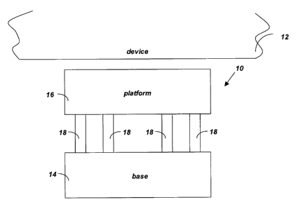
[0008] Figure 1 shows a block diagram of an attenuating system 10 for
attenuating mechanical vibrations in a device 12. In a typical application,
the
device 12 includes audio/video equipment, such as CD players, DVD players,
pre-amplifiers and amplifiers. By reducing vibrations, the system 10 helps
improve the sound quality and fidelity of the audio/video equipment. In
another application, the device can be an operating table at a hospital.
[0009] The system 10 includes a base 14, a platform 16 and
compressible spokes 18 connecting the platform 16 to the base 14.
CA 02511422 2005-07-05
-3-
[0010] The base 14 rests on a surface, such as a floor, desk or cabinet.
The device 12 rests on the platform 16. Compressible spokes 18 connect the
platform 16 to the base 14. Mechanical vibrations of the device 12 are
attenuated as vibrational energy travels from the device 12, to the platform
16,
to the spokes 18 and then finally to the base 14. Most of the vibrational
energy is absorbed before reaching the base 14. Consequently, the surface
on which the base 14 rests, such as a floor, does not vibrate, which is
particularly helpful where such vibrations would inconvenience others, such
as would be the case in a high-rise apartment building.
[0011] The system 10 also finds use in many other areas where a
reduction of mechanical vibrations is desired, such as in operating theaters,
where the elimination of vibrations are important for surgery, especially
microsurgery, and in research environments where precise measurements
require the diminution of unwanted vibrations.
[0012] The compressible spokes 18 may be composed of self-skinned
polyurethane molded foam. In such case, the whole system 10 may be
conveniently composed of polyurethane using a single mold. Other cured or
porous materials may also be used.
[0013] To support a device 12, any number of systems 10 can be used.
Typically, four systems 10 can be placed at the corners of a box-shaped
device 12. However, more or less than four systems 10 may be placed under
the device 12, as appropriate.
[0014] Figures 2A and 2B show in side and plan views, respectively, an
attenuating system 30 for attenuating mechanical vibrations in a device 32,
such as audio/video equipment, consistent with the principles of the present
invention. The system 30 includes a ring-shaped base 34 of diameter d,, and
a disk-shaped platform 36 of diameter d2<d,, the platform 36 being co-axial
with the base 34 and disposed above the base 34. Compressible spokes 38
connect the platform 36 to the base 34.
CA 02511422 2005-07-05
-4-
[0015] The ring-shaped base 34 rests on a surface, such as a floor,
desk or cabinet. The device 32 rests on the disk-shaped platform 36. The
compressible nature of the spokes 38 help to reduce mechanical vibrations of
the device 32, as vibrational energy travels from the disk-shaped platform 36
to the ring-shaped base 34 via the spokes 38.
[0016] The compressible spokes 38 may be composed of self-skinned
polyurethane molded foam. In such case, the whole system 30 may be
conveniently composed of polyurethane using a single mold. If desired, the
external polyurethane surface of the system 30 may be painted. Various
colours that would be attractive alongside the audio/video equipment can be
used.
[0017] The number of compressible spokes 38 is usually three or more.
The precise number can depend on the weight of the device 32. In particular,
as the weight increases, a system 30 with more spokes 38 can be used to
prevent the platform 36 from otherwise collapsing. In addition, the density of
the polyurethane comprising the components of the system 30 can vary
according to the weight of the device 32, the lower the density of the
polyurethane the smaller the weight of the device 32.
[0018] Figures 3A and 3B show in side and plan views, respectively, an
attenuating system 50 for attenuating mechanical vibrations of a device 52.
The system 50 includes a disk-shaped base 54 of diameter d,, and a ring-
shaped platform 56 of diameter d2> d,, the platform 56 being co-axial with the
base 54 and disposed above the base 54. Compressible spokes 58 connect
the platform 56 to the base 54.
[0019] As will immediately be recognized, system 50 is the same as
system 30 but inverted so that the device 52 rests on the wider ring-shaped
platform 56 instead of the narrower disk shaped base 54. The disk-shaped
base 54 rests on a surface, such as a floor, desk or cabinet. The
compressible nature of the spokes 58 help to reduce mechanical vibrations of
the device 52, as vibrational energy travels from the ring-shaped platform 56
CA 02511422 2005-07-05
-5-
to the disk-shaped base via the spokes 58. As described above, the system
50 may be composed of polyurethane and derived from a single mold.
[0020] Figure 4 shows a stack system 70 comprised of the systems 30
and 50 of Figures 2 and 3. Such a stack system 70 is formed by stacking
systems 30 and 50 so that the disk-shaped platform 36 abuts the disk-shaped
base 54. The ring-shaped base 34 rests on a surface, such as a floor, and
the device 52 rests on the ring-shaped platform 56. The stack system 70 can
be used to attenuate particularly large mechanical vibrations, where system
30 or system 50 alone might not be adequate. Another application of the
stack formation arises when the height of device 32 resting thereon needs to
be raised. It should be appreciated that a plurality of pairs of systems 30
and
50 may be stacked to form a stack system 70 that is arbitrarily tall.
[0021] Figure 4 shows the system 50 of Figure 3 stacked on top of the
system 30 of Figure 2. It should be understood that in another embodiment,
system 30 may be stacked on top of system 50. In such case, the disc-
shaped base rests on a surface, such as a floor or cabinet surface, while the
device 32 rests on the disc-shaped platform 36.
[0022] Figure 5A shows an attenuating system 90 exemplifying another
embodiment for attenuating mechanical vibrations of a device 92. The system
90 includes a three-walled, box-shaped base 94, a rectangular-shaped
platform 96 and compressible spokes 98 connecting the platform 96 to the
base 94. The spokes 98 are individually removably attached to the platform
96 and to the base 94.
[0023] The base 94 rests on a surface, such as a floor, desk or cabinet.
The device 92 rests on the platform 96. Compressible spokes 98 connect the
platform 96 to the base 94. Mechanical vibrations of the device 92 are
attenuated as vibrational energy travels from the device 92, to the platform
96,
to the spokes 98 and then finally to the base 94, with most of the vibrational
energy being absorbed before reaching the base 94.
CA 02511422 2005-07-05
-6-
[0024] Figure 5B shows an exploded view of a portion of Figure 5A with
the platform 96 omitted, and Figure 5C shows an exploded view of the
underside 100 of the platform 96 of Figure 5A with the base 94 omitted. In
Figure 5B, three base female receptors 102, 104 and 106 are shown on the
base 94. In Figure 5C, three complementary platform female receptors 108,
110 and 112 are shown on the underside 100 of the platform 96.
[0025] Each of the female receptors 102, 104 and 106 can receive a
single compressible spoke 98. One compressible spoke 98 is shown, one
portion 114 of which is manually inserted into the base female receptor 104.
An opposite portion 116 is inserted into the complementary platform female
receptor 110 on the underside 100 of the platform 96.
[0026] Although Figures 5B and 5B each only display three female
receptors 102, 104 and 106, and 108, 110 and 112, it should be understood
that more receptors are present around the periphery of both the base 94 and
platform 96. For a particular application, however, not all receptors need
contain a spoke 98. The number of spokes 98 present in the system 90
depends on the amplitude of the mechanical vibrations that are to be
attenuated and on the weight of the device, the greater the amplitude or
weight, the larger the number of spokes 98 that can be used. By adding
enough spokes 98, collapse of the platform 96 due a heavy device 92 resting
thereon is avoided. The spokes 98 are individually removable by hand and fit
into the female receptors 102, 104 and 106, and 108, 110 and 112. Because
the spokes 98 are compressible, they may be made to fit snugly, perhaps by
having to squeeze the spokes 98 before insertion into the receptors. Each
spoke 98 is bone-shaped with two "knobs" on either side. The knobs prevent
the spokes from sliding out of the receptors 102, 104 and 106, and 108, 110
and 112 under the weight of the device 92. That is, although the spokes 98
are designed to stretch when a device 92 is placed on the platform, the knobs
do not stretch to the point where the spoke 98 can slip out of the receptor.
It
should be understood that the density and the size of the spokes 98 (and the
CA 02511422 2005-07-05
-7-
size of the corresponding receptors) may vary. For example, a heavier device
load might require the use of denser or larger receptors.
[0027] The embodiment that is the system 90 of Figure 5 may be
modified in a number of ways. First, the rear vertical wall of the base 94 and
the rear edge of the platform 96 may also include receptors. By inserting
spokes 98 therein, the base 94 and the platform 96 may be further connected
at the rear. In addition, the base 94 may be constructed to include a front
fourth wall, whose height may be different than the heights of the other three
walls of the base 94. For example, the front fourth wall may be shorter than
the other three walls with the top of the front wall substantially flush with
the
platform 96. Making the front fourth wall shorter in this manner allows
devices
to be easily inserted into a stack arrangement of systems 90 (see Figure 6,
described below).
[0028] It should also be understood that the "linear density" of spokes
98 (i.e., the number of spokes per unit length) and/or receptors need not be
uniform along the various walls of the base 94. If the system 90 is designed
for a device that has a non-uniform weight distribution, then more receptors
and spokes can be added to whichever side bears the greater amount of
weight of the device.
[0029] The base 94 and platform 96 can be composed of any one of
number of materials including wood, plywood, MasoniteT"", acrylic and
medium density fiberboard (MDF). The spokes 98 can be composed of any
compressible material, such as polyurethane.
[0030] Figure 6 shows a system 130 for attenuating mechanical
vibrations that is comprised of a plurality of the attenuating systems 90
stacked one on top of each other. The back wall of the base 94 can have a
gap at the bottom to allow electrical wires from the device 92 to exit the
back.
The system can accommodate several devices 92, 132 and 134. For
example, the devices 92, 132 and 134 can be components of an audio/video
system, such as a CD player, amplifier and DVD player.
CA 02511422 2005-07-05
_$_
[0031] Figures 7A and 7B show a plan view and cross section of a
system 150 for attenuating mechanical vibrations of a device 152, especially
designed for devices such as speaker systems but which may also be used
for other devices that produce unwanted vibrations. The system 150 includes
a compressible component 154 and a dense component 156. The
compressible component 154 can be composed of polyurethane, for example.
The dense component 156 has a covered portion 158 and an uncovered
portion 160. The covered portion 158 is covered and in contact with the
compressible component 154.
[0032] The dense component 156 need not be monolithic, but can
instead be made from a number of subparts. In one embodiment, for
example, a center core of the dense component 156 may be hollow. Later in
the manufacturing process, a complementary piece of dense component can
be removably or, preferably, permanently inserted into the hollow center core.
[0033] The device 152 rests on a part of the uncovered portion 160,
vibrational energy from the device 152 being attenuated by the compressible
component 154.
[0034] In the embodiment of the system 150 shown in Figure 7, the
system 150 is disk-shaped. The disk has an external surface the largest
fraction of which is composed of the compressible component 154. A smaller
fraction of the external surface, near the center of the disk on either side
thereof, is composed of the dense component 156. At the center of the disk,
on either side, is a notch 162 that can be used with speaker systems, and
other audio/video equipment, having spikes 163 at the base. Each spike 163
of the speaker system can be inserted into a notch 162.
[0035] Because the dense component 156 is designed to sustain the
pressure below the notch 162 due to the weight of the device 152, it is
desirable that the dense component 156 be composed of a dense material,
such as acrylic, nylon, plastic, polyvinylchloride or any other material that
can
be injected and which dries to form a dense solid.
CA 02511422 2005-07-05
_g_
[0036] A component of an audio/video system typically contains four
spikes 163 at the base, and under each such spike 163, a system 150 can be
placed to attenuate vibrations.
[0037] Vibrational energy is received from the device 152 by the dense
component 156. In turn, the dense component 156 transmits the vibrational
energy to the compressible component 154, where the vibrations are
dampened.
[0038] In other applications, the system 150 can be used for devices
having no spikes. For example, spikeless speakers can rest directly on the
compressible component 154. Likewise, the legs of an operating table can
rest directly on the compressible component to reduce vibrations of the table
during an operation.
[0039] It should be understood that various modifications could be
made to the embodiments described and illustrated herein, without departing
from the present invention. For example, although emphasis has been placed
on a system for attenuating mechanical vibrations in audio/video equipment,
the present system and method can be also applied to other devices where
unwanted vibrations exist, such as medical equipment, and manufacturing
equipment. The scope of the invention is defined in the appended claims.