Note: Descriptions are shown in the official language in which they were submitted.
CA 02512208 2005-06-29
WO 2004/061460 PCT/US2003/041329
IMPLANTABLE MARKER WITH A WIRELESS SIGNAL TRANSMITTER COMPATIBLE
FOR USE IN MAGNETIC RESONANCE IMAGING DEVICES AND/OR SUITABLE FOR
USE IN RADIATION IMAGING PROCESSES
TECHNICAL FIELD
The present invention is directed toward markers with signal transmitters that
wirelessly transmit location signals. The markers are compatible for use in
magnetic
resonance devices and/or suitable for use in radiation imaging processes.
Several
embodiments of the markers are permanently implantable or semi-permanently
implantable
in patients for locating at least one target in and/or on the patient.
BACKGROUND
Medical procedures often require locating and treating target areas within a
patient.
Radiation therapy and many surgical procedures require locating the target
with a high
degree of precision to limit collateral damage to healthy tissue around the
target. It is
particularly important to know or estimate the precise location of the target
in radiation
oncology because it is (a) desirable to accurately determine the accumulated
dosage
applied to the target and (b) detrimental to expose adjacent body parts to the
radiation. In
applications for treating prostate cancer, for example, it is detrimental to
irradiate the colon,
bladder or other neighboring body parts with the high-intensity radiation
beam. Surgical
applications, such as breast surgery and other procedures involving soft
tissue, also require
knowing the precise location of a target because a lesion in soft tissue is
not necessarily
fixed relative to external landmarks on the patient.
Many imaging systems have been used to locate areas or particular targets in a
patient before performing radiation oncology or surgical procedures. Although
x-ray,
Magnetic Resonance Imaging (MRI), CT and other imaging techniques are useful
to locate
targets within the body at a pre-operative stage of a procedure, they are
often not suitable
or difficult to use in real time during surgery or radiation therapy. For
example, the location
of a lesion in soft tissue or in an organ may shift relative to external
landmarks on the
patient between the pre-operative imaging procedure and the actual radiation
or surgical
procedure. Additionally, when imaging systems are used during a radiation or
surgical
procedure, they may not provide sufficiently accurate measurements of the
location of the
lesions and they may interfere with the radiation or surgical procedure.
Therefore, imaging
CA 02512208 2005-06-29
WO 2004/061460 PCT/US2003/041329
techniques by themselves are generally not well suited for accurately
identifying the actual
location of a target for many medical applications.
Another technique to locate a target in a patient is to implant a marker
relative to the
target. Several types of tags or markers with resonating magnetic circuits
have been
developed to track feeding tubes, tag items, and mark tissue. For example,
implantable
markers that generate a signal have been proposed for use to locate a selected
target in a
patient in radiation oncology procedures. U.S. Patent No. 6,385,482 B1 issued
to
Boksberger et al. discloses a device having an implanted emitter unit located
inside or as
close as possible to a target object, and a plurality of receiver units that
are located outside
of the patient. Boksberger discloses determining the location of the target
object by
energizing the emitter unit using a generator and sensing the signal from the
emitter unit
with the receiver units. Boksberger discloses and claims that the receiver
units are
configured to determine the gradient of the magnetic field generated by the
emitter unit.
Boksberger further discloses that the emitter unit is energized using a wired
connection to
the external generator. Boksberger also indicates that it is conceivable to
use an emitter
unit that is energized by a battery or excited by an electromagnetic field
generated by the
external generator. The wired device disclosed in Boksberger, however, may not
be
suitable for use in radiation oncology and many surgical procedures because it
is
impractical to leave a wired marker implanted in a patient for the period of
time of such
procedures (e.g., five to forty days). Moreover, Boksberger does not disclose
or suggest
anything with respect to providing an implantable emitter unit that is (a)
suitable for use in
radiation imaging processes or (b) compatible for use in magnetic resonance
imaging
devices after being implanted in a patient.
Another technique to locate a target in a patient is to implant passive, gold
fiducials
in or near the target site. The positions of the gold fiducials are determined
periodically
using radiation. Although gold fiducials are useful for localizing a target
within a patient,
these systems do not provide sufficiently accurate real time measurements of
the target
site location during radiation oncology procedures.
Other types of tags or markers with resonating magnetic circuits have been
developed. These markers have been used to tag sponges and other items used
during
surgery or locate the general location of feeding tubes or other instruments
in other
procedures. One significant challenge of miniature, wireless markers is to
provide a
sufficiently strong signal to be accurately detected by sensors outside of the
body.
Additionally, a challenge of using markers with resonating magnetic circuits
is
determining the relative location between the marker and the target so that
the target can
-2-
CA 02512208 2005-06-29
WO 2004/061460 PCT/US2003/041329
be tracked during a procedure or therapy. Accurately determining the location
of the
marker relative to the target is a precondition for accurately tracking the
target based on the
resonating magnetic field generated by the implanted marker. One reason that
it is difficult
to accurately determine the location of the marker relative to the target is
that it can be
difficult to identify magnetic resonating markers in radiographic images. The
markers are
difficult to see in radiographic images because (a) they should be very small
so that they
may be implanted for an extended period of time, and (b) they may not be
sufficiently
visible in high voltage radiation applications (i.e., megavolt radiation
imaging). Moreover,
even when a magnetic marker can be identified in an image, it can still be
challenging to
determine the orientation of the magnetic field generated by the marker
relative to the
target because it is often difficult to determine the orientation of the
marker in the image.
As such, implantable markers with resonating magnetic circuits may be
difficult to use in
radiation therapies and surgical procedures that require highly accurate
localization of the
target.
BRIEF DESCRIPTION OF THE DRAWINGS
Figure 1 is an isometric view of an implantable wireless marker in accordance
with
an embodiment of the invention with a section cut away to illustrate internal
components.
Figure 2 is a cross-sectional view taken along a longitudinal axis of an
embodiment
of the marker of Figure 1.
Figure 3 is a cross-sectional view in a plane normal to a longitudinal axis of
a
marker in accordance with an embodiment of the marker shown in Figure 1.
Figure 4 is a cross-sectional view taken along a longitudinal axis of a marker
in
accordance with an embodiment of the invention after being implanted in a
patient.
Figure 5 is a diagram of a display of a magnetic resonance image with an
artifact by
a magnetic marker.
Figure 6 is a cross-sectional view taken along a longitudinal axis of a marker
in
accordance with another embodiment of the invention.
Figure 7A is an isometric view of a wireless marker in accordance with an
embodiment of the invention with a section cut away to illustrate internal
components.
Figure 7B is a cross-sectional view of the wireless marker of Figure 7A taken
along
line 7B-7B.
Figure 7C is an illustration of a radiographic image of the marker of Figures
7A-B.
Figure 8A is an isometric view of a wireless marker in accordance with another
embodiment of the invention.
-3-
CA 02512208 2005-06-29
WO 2004/061460 PCT/US2003/041329
Figure 8B is a cross-sectional view of the wireless marker of Figure 8A taken
along
line 8B-8B.
Figure 9A is an isometric view of a wireless marker in accordance with another
embodiment of the invention.
Figure 98 is a cross-sectional view of the wireless marker of Figure 9A taken
along
line 9B-9B.
Figure 10 is an isometric view of a wireless marker in accordance with yet
another
embodiment of the invention with a section cut away to illustrate internal
components.
Figure 11 is an isometric view of a wireless marker in accordance with still
another
embodiment of the invention with a section cut away to illustrate internal
components.
DETAILED DESCRIPTION
A. Overview
The following disclosure describes several embodiments of wireless markers
configured to be attached to a patient either by being implanted into the
patient or adhered
externally to the skin of the patient. Several embodiments of the markers are
highly
suitable for use in radiographic imaging systems and other types of imaging
systems to
determine the location and orientation of the magnetic field with respect to
the target of the
patient. Other embodiments of the markers are compatible for use in powerful
magnetic
fields generated by magnetic resonance imaging devices either in addition to
or in lieu of
being suitable for use in radiographic imaging systems. Several embodiments
and features
of markers in accordance with the invention are set forth and described in
Figures 1-11. It
will be appreciated that other embodiments of markers in accordance with the
invention can
include additional or different features than those shown in Figures 1-11.
Additionally, it will
be appreciated that several embodiments of markers in accordance with the
invention do
not include all of the features shown in these figures. For purposes of
brevity, like
reference numbers refer to similar or identical components.
One embodiment of a wireless marker for localizing the position of a target
within a
patient comprises:
a casing configured to be positioned at a selected location relative to a
target site in
the patient;
a resonating circuit without external electrical lead lines extending through
the
casing, the resonating circuit having an inductor within the casing comprising
a plurality of windings of a conductor; and
-4-
CA 02512208 2005-06-29
WO 2004/061460 PCT/US2003/041329
a ferromagnetic element at least partially within the inductor, the
ferromagnetic
element having a volume such that when the marker is in an imaging
magnetic field having a field strength of 1.5 T and a gradient of 3 T/m, then
force exerted on the marker by the imaging magnetic field is not greater than
gravitational force exerted on the marker.
Another embodiment of a wireless marker for localizing the position of a
target
within a patient comprises:
a casing configured to be permanently implanted in the patient;
a ferromagnetic element in the casing, the ferromagnetic element having a
volume
such that when the marker is in an imaging magnetic field having a field
strength of 1.5 T and a gradient of 3 T/m, then force exerted on the marker
by the magnetic field is not greater than gravitational force exerted on the
marker; and
a resonating circuit without external electrical lead lines extending through
the
casing, the resonating circuit having an inductor within the casing comprising
a plurality of windings of a conductor around at least a portion of the
ferromagnetic element, wherein the resonating circuit is configured to be
energized by an excitation magnetic field and produce a response signal for
identifying the position of the marker relative to a reference sensor
assembly.
Still another embodiment of a wireless marker for localizing the position of a
target
within a patient comprises:
a ferromagnetic core having a length and a cross-sectional dimension normal to
the
length, wherein the cross-sectional dimension is not greater than 0.7 mm;
a resonating circuit comprising a conductive element having a plurality of
windings
surrounding at least a portion of the ferromagnetic core, wherein the
resonating circuit is not coupled to external electrical leads; and
a casing around the ferromagnetic core and the resonating circuit.
Yet another embodiment of a wireless marker for localizing the position of a
target
within a patient comprises:
a ferromagnetic core having an outer diameter not greater than approximately
0.7
mm;
a coil having windings positioned around at least a portion of the core; and
a casing around the core and the coil without external electrical leads
projecting
from the casing.
-5-
CA 02512208 2005-06-29
WO 2004/061460 PCT/US2003/041329
An alternative embodiment of a wireless marker for localizing the position of
a target
within a patient comprises]
a ferromagnetic core having a volume that produces an image artifact not
greater
than 1500 mm2 in an image from a magnetic resonance device using a
magnetic field strength of 1.5 T and a gradient of 3 T/m;
a resonating circuit comprising a conductive element having a plurality of
windings
surrounding at least a portion of the ferromagnetic core, wherein the
resonating circuit is not coupled to external electrical leads; and
a casing enclosing the core and the resonating circuit.
Yet a further embodiment of a wireless marker for localizing the position of a
target
within a patient comprises:
a ferromagnetic element having a first end and a second end;
a resonating circuit comprising an inductor having a plurality of windings of
a
conductor surrounding at least a portion of the ferromagnetic element and a
capacitor at the first end of the ferromagnetic element;
a module at the second end of the ferromagnetic element, the module being
symmetrical relative to the capacitor; and
a casing around the ferromagnetic element, the resonating circuit and the
module.
Alternative embodiments of wireless markers can be suitable for radiographic
imaging in addition to or in lieu of being compatible with magnetic resonance
imaging
equipment. For example, one embodiment of a wireless marker for localizing a
target of a
patient comprises a casing and a magnetic transponder at least partially
received in the
casing. The magnetic transponder produces a wirelessly transmitted magnetic
field in
response to a wirelessly transmitted excitation energy. The magnetic
transponder also has
a magnetic centroid. The marker also comprises an imaging element carried by
the casing
and/or the magnetic transponder. The imaging element has a radiographic
profile in a
radiographic image such that the marker has a radiographic centroid at least
approximately
coincident with the magnetic centroid.
The imaging element can have several different configurations and be composed
of
many different materials. For example, to be visible on megavoltage x-ray
images, the
imaging element can comprise a single contrast element or a plurality of
contrast elements
composed of a high density material and having a sufficient thickness and
cross-sectional
area to absorb a substantial fraction of photons incident on the imaging
element. The
image is formed by the reduction of photon flux density in the path from the x-
ray source
through the imaging element to a radiographic imaging device or film. In other
applications
-6-
CA 02512208 2005-06-29
WO 2004/061460 PCT/US2003/041329
that use lower acceleration voltages for the imaging radiation, the imaging
element can be
a contrast element having a lower density or a different configuration that is
not suitable for
use with megavoltage x-ray images.
In one embodiment the imaging element comprises first and second contrast
elements configured symmetrically with respect to the magnetic transponder.
The first and
second contrast elements can comprise first and second rings positioned
symmetrically
with respect to the radiographic and magnetic centroids. The first and second
rings can be
continuous rings or discontinuous members having a gap. The first and second
contrast
elements can alternatively be spheres, cubes, or other suitable shapes for
identifying the
profile of the marker in a radiographic image.
Another embodiment of a wireless marker for localizing a target of a patient
in
accordance with the invention comprises a casing and a magnetic transponder in
the
casing. The magnetic transponder produces a wirelessly transmitted magnetic
field in
response to a wirelessly transmitted excitation field, and it has a first
density. The marker
of this embodiment further comprises an imaging element carried by the casing
and/or the
magnetic transponder. The imaging element has a second density greater than
the first
density of the magnetic transponder.
In yet another embodiment of the invention, a wireless marker for localizing a
target
of a patient comprises a casing and a magnetic transponder that produces a
wirelessly
transmitted magnetic field in response to a wirelessly transmitted excitation
field. The
marker further comprises an imaging element (e.g., a contrast element) carried
by the
casing and/or the magnetic transponder. In this embodiment, the imaging
element is
sufficiently absorbent of incident photon fluence of a megavolt photon therapy
beam to be
visible in a radiographic image generated using such a therapy beam.
Another embodiment of the wireless marker for localizing a target in a patient
comprises a casing and a magnetic transponder that produces a wirelessly
transmitted
magnetic field in response to a wirelessly transmitted excitation field. The
marker of this
embodiment further comprises an imaging element carried by the casing and/or
the
magnetic transponder. The imaging element of this embodiment has a density of
at least
19 g/cm3.
The invention further includes methods for tracking a target of a patient. For
example, one embodiment of such a method comprises imaging a marker attached
to the
patient using a first energy to obtain an image of the marker. The marker has
a magnetic
transponder that produces a wirelessly transmitted signal in response to a
wirelessly
-7-
CA 02512208 2005-06-29
WO 2004/061460
PCT/US2003/041329
_
transmitted excitation energy. The method further includes locating the marker
by
transmitting the excitation energy to the marker.
B. Embodiments of Markers for Use In MRI Procedures
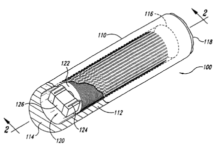
Figure 1 is an isometric view of an implantable marker 100 in accordance with
an
embodiment of the invention with a portion cut away to illustrate internal
components. The
embodiment of the marker 100 shown in Figure 1 includes a casing 110 and a
magnetic
transponder 120 (e.g., a resonating circuit) in the casing 110. The terms
magnetic
transponder 120 and resonating circuit 120 are used interchangeably
throughout. The
casing 110 is a biocompatible barrier configured to be implanted in the
patient or otherwise
attached to the patient. The casing 110 can be a generally cylindrical capsule
that is sized
to fit within a 14 gauge needle for percutaneous implantation, but the casing
can have
other configurations and be larger or smaller. The casing 110, for example,
can have barbs
to anchor the casing 110 in soft tissue or an adhesive for attaching the
casing 110
externally to the skin of a patient. Suitable anchoring devices are disclosed
in International
Publication No. WO 02/39917 Al, which designates the United States and is
incorporated
herein by reference. In one embodiment, the casing 110 includes (a) a glass
capsule or
shell 112 having a closed end 114 and an open end 116, and (b) a sealant 118
in the open
end 116 of the shell 112. The casing 110 and sealant 118 can be made from
plastics,
ceramics, glass or other suitable biocompatible materials.
The resonating circuit 120 produces a wirelessly transmitted signal in
response to a
wirelessly transmitted excitation signal. In one embodiment, the resonating
circuit 120
comprises a coil 122 defined by a plurality of windings of a conductor 124.
Many
embodiments of the resonating circuit 120 also include a capacitor 126 coupled
to the coil
122. The coil 122 resonates at a selected resonant frequency. The coil 122 can
resonate
at the selected resonant frequency solely using the parasitic capacitance of
the windings
without having a capacitor, or the selected resonant frequency can be produced
using the
combination of the coil 122 and the capacitor 126. The coil 122 by itself or
in combination
with the capacitor 126 accordingly defines a signal transmitter that generates
an alternating
magnetic field at the selected resonant frequency in response to the
excitation signal. The
conductor 124 of the illustrated embodiment can be hot air or alcohol bonded
wire having a
gauge of approximately 45-52. The coil 122 can have 800-2000 turns. The
windings are
preferably wound in a tightly layered coil.
The resonating circuit 120 is powered by a wirelessly transmitted excitation
signal
such that the resonating circuit is leadless, i.e., not connected to external
lead wires which
extend through or project from the casing 110. In one embodiment, the
resonating circuit
-8-
CA 02512208 2005-06-29
WO 2004/061460 PCT/US2003/041329
120 can be energized by an alternating excitation magnetic field generated
externally with
respect to the patient at the resonant frequency of the resonating circuit. In
response to
the excitation field, the resonating circuit 120 produces a marker signal or
response signal
that can be measured by a sensor array positioned externally with respect to
the patient.
Suitable devices for generating the magnetic excitation field and sensing the
marker signal
are disclosed in U.S. Patent Application Nos. 10/027,675 filed on December 20,
2001;
10/044,056 filed on January 11,2002; and 10/213,980 filed on August 7,2002,
all of which
are herein incorporated by reference.
Figure 2 is a cross-sectional view of an embodiment of the marker 100 taken
along
a longitudinal axis 2-2 shown in Figure 1. The marker 100 further includes a
ferromagnetic
element 140 having a first end 142 and a second end 144. The ferromagnetic
element 140
is at least partially surrounded by the coil 122. In the particular embodiment
shown in
Figure 2, the coil 122 surrounds the ferromagnetic element 140 from the first
end 142 to the
second end 144. In other embodiments, the coil 122 surrounds only a portion of
the
ferromagnetic element 140. The capacitor 126 can be positioned at the first
end 142 of the
ferromagnetic element 140. Additionally, the resonating circuit 120 and the
ferromagnetic
element 140 can be fixed to the casing 110 by an adhesive 150.
The ferromagnetic element 140 is preferably composed of ferrite or other
materials
that have high magnetic permeability compared to free space. The amount of
energy that
the inductor is capable of storing is limited, in part, by the magnetic field
saturation of the
ferromagnetic element 140. To store more energy in a miniature wireless
marker, the prior
art taught that the size of the ferromagnetic material should be maximized
within the limited
space of the marker. As shown in Figure 2, however, the volume of the
ferromagnetic
element 140 is significantly less than the available volume within the casing
110. The
smaller volume of the ferromagnetic element 140 reduces the force exerted on
the marker
100 when the marker 100 is placed in a magnetic resonance imaging device
having a
magnetic field strength of 1.5 T with a corresponding gradient field of
approximately 3 T/m.
In one embodiment, the ferromagnetic element has a volume such that when the
marker is
in a magnetic resonance device, then the force exerted on the marker by the
magnetic field
is less than gravitational force exerted on the marker. Additionally, the
small volume of the
ferromagnetic element 140 reduces the size of the artifact in an image from a
magnetic
resonance device. It will be appreciated that ferromagnetic materials will
produce an
artifact (i.e., a region in which image information is suppressed) in an image
produced by a
magnetic resonance imaging device. The volume of the ferromagnetic element 140
can be
reduced to a size such that it produces a small artifact in an image from a
magnetic
-9-
CA 02512208 2005-06-29
WO 2004/061460 PCT/US2003/041329
resonance device. In general, such ferromagnetic elements 140 have small
diameters less
than the size of commercially available ferrite rods for transponder
applications, which are
as small as 0.75mm in diameter (i.e., ferrite rods available from Ferroxcube
of Spain).
Figure 3 is a cross-sectional view of the marker 100 taken along line 3-3 of
Figure 2.
In one embodiment, the ferromagnetic element 140 is a ferrite rod having a
diameter D1 of
approximately 0.20-0.70 mm, but the ferromagnetic element 140 can have other
cross-
sectional configurations in other embodiments. For example, an extruded
ferrite rod can
have an elliptical, oval or polygonal cross section. The ferromagnetic element
140 can
have a length of approximately 2.0-20 mm. In
one particular embodiment the
ferromagnetic element 140 has a diameter of approximately 0.25-0.50 mm and a
length of
2-12 mm, and in another embodiment the ferromagnetic element 140 has a
diameter of
0.30-0.35 mm and a length of 4.0-6.0 mm. The coil 122 has an inner diameter of
approximately 0.20-0.80 mm and an outer diameter D2 of approximately 0.6-1.4mm
or 0.8-
1.9 mm. The casing 110 can have an outer diameter D3 of approximately 1.0-3.0
mm. In
other embodiments, the coil 122 can have different inner and outer diameters,
and the
casing 110 can have a different outer diameter. In another particular
embodiment, the
diameter D1 of the ferromagnetic element 140 is approximately 0.30-0.50 mm,
the inner
diameter of the coil 122 is approximately 0.30-0.60 mm, the outer diameter D2
of the coil
122 is approximately 1.2-1.9 mm (or 1.2-1.4 mm), and the outer diameter D3 of
the casing
110 is approximately 1.8-2.0 mm. The volume of the ferromagnetic element 140
can be
approximately 0.5-19.0 mm3.
The marker 100 is constructed by manufacturing the ferromagnetic element 140,
placing the coil 122 around the ferromagnetic element 140, and encapsulating
the
resonating circuit 120 and the ferromagnetic element 140 in the casing 110.
The
ferromagnetic element 140 can be manufactured using extrusion, coring, or high
pressure
molding processes to form a ferrite rod having a diameter of approximately 0.2-
0.7 mm.
The coil 122 is formed by winding the conductor 124 around either the
ferromagnetic
element 140, a sleeve around the ferromagnetic element 140, or a mandrel
separate from
the ferromagnetic element 140. In one embodiment, the conductor 124 is wrapped
directly
onto the ferromagnetic element 140, but this may not be feasible in many
applications
because it may break ferromagnetic elements having a diameter less than 0.5
mm. In
another embodiment, a retractable sleeve can slide along the ferromagnetic
element 140
as the conductor 124 is wound directly onto the ferromagnetic element. The
sleeve is
expected to support the ferromagnetic element 140 as the first layer of turns
are wrapped
around the ferromagnetic element 140. The first layer of turns supports the
rod so that
-10-
CA 02512208 2005-06-29
WO 2004/061460 PCT/US2003/041329
subsequent layers of turns can be wound onto the first layer. In still another
embodiment,
the coil 122 is wound around a mandrel separately from the ferromagnetic
element 140.
The coil 122 is then removed from the mandrel and the ferromagnetic element
140 is
inserted into the inner diameter of the coil 122. This embodiment can result
in a small gap
between the ferromagnetic element 140 and the inner diameter of the coil 122.
This gap
should be minimized in optimal circumstances to increase the performance of
the
resonating circuit 120. After the ferromagnetic element 140 is positioned
within the coil
122, this assembly is adhered to the casing 110 using the adhesive 150, and
the sealant
118 is used to close the open end 116 of the casing 110.
Figure 4 is a representative view of the operation of the marker 100 in an
magnetic
field M generated by a magnetic resonance imaging device (not shown). The
magnetic
field M is an imaging magnetic field. In this embodiment, a patient is placed
in a magnetic
resonance imaging device to image a portion P of the patient. The imaging
magnetic field
M includes a plurality of flux lines F. Because the ferromagnetic element 140
has a high
magnetic permeability, the ferromagnetic element 140 exerts a magnetic force
Fm in the
presence of the magnetic field M due to the presence of DC and gradient
magnetic fields.
The magnitude of the magnetic force Fm is a function of the volume and the
type of material
(i.e., magnetic saturation) of the ferromagnetic element 140. The
volume of the
ferromagnetic element 140 is selected so that the magnetic force Fm caused by
the
interaction between the ferromagnetic element 140 and the magnetic field M is
less than
the gravitational force FG exerted against the marker 100. This will ensure
that the
magnetic field M does not cause the marker 100 to move within the portion P of
the patient
any more than the force of gravity will cause movement of the marker 100.
Figure 5 is a schematic representation of a magnetic resonance image 500 that
shows a target location T within a body part of a patient. The image 500
includes an
artifact 510 caused by the ferromagnetic element 140 of the marker 100. The
artifact 510
is typically much larger than the size of the marker, and thus it tends to
obscure the actual
location of the marker and the images of tissue adjacent to the marker. The
size of the
artifact 510 is related to the size of the ferromagnetic element 140 in the
marker 100. In
several embodiments, the volume of the ferromagnetic element 140 is selected
to produce
an artifact not greater than 1,500 mm2 in an image produced by a resonance
imaging
device field having a DC field strength of 1.5 T. In other embodiments, the
volume of the
ferromagnetic element 140 is selected to produce an artifact not greater than
400-1,200
mm2, and in other cases not greater than 400-800 mm2 in an image produced by a
magnetic resonance imaging device field having a DC field strength of 1.5 T.
-11-
CA 02512208 2005-06-29
WO 2004/061460 PCT/US2003/041329
C. Embodiments of Markers with Enhanced Radiographic Properties
Figure 6 is a cross-sectional view of a marker 600 in accordance with another
embodiment of the invention. The marker 600 is substantially similar to the
marker 100
shown in Figure 2, but the marker 600 further includes a module 610 at the
second end
144 of the ferromagnetic element 140. The module 610 is preferably configured
to be
symmetrical with respect to the capacitor 126 at the first end 142 of the
ferromagnetic
element 140. The module 610, more specifically, is configured to produce a
similar
radiographic image as the capacitor 126 in an x-ray. In one embodiment, the
module 610
is configured such that the magnetic centroid of the marker is at least
substantially
coincident with the radiographic centroid of the marker. In other embodiments
that use CT
or other types of imaging modalities, the module 610 is configured to produce
a
symmetrical image relative to the capacitor 126. For example, the module 610
can be
another capacitor identical to the capacitor 126 that may or may not be
electrically coupled
to the coil 122. In other embodiments, the module 610 can be an electrically
inactive
element that is not electrically connected to the resonating circuit 120 or
another type of
electrically active element that is electrically coupled to the resonating
circuit 120. Suitable
electrically inactive modules include ceramic blocks shaped like the capacitor
126. In either
case, one purpose of the module 610 is to have the same characteristics as the
electrically
active capacitor 126 in x-ray, CT, and other imaging techniques. Since the
markers may be
located via radiographic methods (e.g., CT, or x-ray) to determine the marker
centroid
positions relative the target tissue prior to therapy, an error in the
position of the marker
radiographic and magnetic centroids may result in a fixed positional error
during therapy.
Figure 7A is an isometric view of a marker 700 in accordance with an
embodiment
of the invention with a portion cut away to illustrate internal components.
The marker 700
shown in Figure 7A is similar to the marker 100 shown in Figure 1 or the
marker 600 shown
in Figure 6, and like reference numbers refer to like components. As such, the
embodiment
of the marker 700 shown in Figure 7 includes a casing 110 and a magnetic
transponder
120 in the casing 110. The magnetic transponder 120 can be a resonating
circuit that
produces a wirelessly transmitted signal in response to a wirelessly
transmitted excitation
field. The magnetic transponder 120 can accordingly comprise the coil 122, the
capacitor
126, and a core 728. The core 728 can be a ferromagnetic element that is
configured to be
compatible in MRI devices as set forth above with reference to Figures 1-6,
but the core
728 need not be MRI compatible. As such, the core 728 does not necessarily
have the
same dimensions as the ferromagnetic element 140 described above in Figures 1-
6.
-12-
CA 02512208 2005-06-29
WO 2004/061460 PCT/US2003/041329
The marker 700 also includes an imaging element that enhances the radiographic
image of the marker to make the marker more discernible in radiographic
images. The
imaging element also produces a radiographic profile in a radiographic image
such that the
marker has a radiographic centroid at least approximately coincident with the
magnetic
centroid of the magnetic transponder 120. As explained in more detail below,
the
radiographic and magnetic centroids do not need to be exactly coincident with
each other,
but rather can be within an acceptable range.
Figure 7B is a cross-sectional view of the marker 700 along line 7B-7B that
illustrates an adhesive 729 to adhere the magnetic transponder 120 to the
casing 110 and
an imaging element 730 in accordance with an embodiment of the invention. The
imaging
element 730 illustrated in Figures 7A-B includes a first contrast element 732
and second
contrast element 734. The first and second contrast elements 732/734 are
generally
configured with respect to the magnetic transponder 120 so that the marker 700
has a
radiographic centroid Rc that is at least substantially coincident with the
magnetic centroid
Mc of the magnetic transponder 120. For example, when the imaging element 730
includes
two contrast elements, the contrast elements can be arranged symmetrically
with respect to
the magnetic transponder 120 and/or each other. The contrast elements can also
be
radiographically distinct from the magnetic transponder 120. In such an
embodiment, the
symmetrical arrangement of distinct contrast elements enhances the ability to
accurately
determine the radiographic centroid of the marker 700 in a radiographic image.
The first and second contrast elements 732/734 illustrated in Figures 7A-B are
continuous rings positioned at opposing ends of the core 728. The first
contrast element
732 can be at or around a first end 736a of the core 728, and the second
contrast element
734 can be at or around a second end 736b of the core 728. The continuous
rings shown
in Figures 7A-B have substantially the same diameter and thickness. The first
and second
contrast elements 732/734, however, can have other configurations and/or be in
other
locations relative to the core 728 in other embodiments. For example, the
first and second
contrast elements 732/734 can be rings with different diameters and/or
thicknesses.
The radiographic centroid of the image produced by the imaging element 730
does
not need to be absolutely coincident with the magnetic centroid Mc, but rather
the
radiographic centroid and the magnetic centroid should be within an acceptable
range. For
example, the radiographic centroid Rc can be considered to be at least
approximately
coincident with the magnetic centroid Mc when the offset between the centroids
is less than
approximately 5 mm. In more stringent applications, the magnetic centroid Mc
and the
radiographic centroid R, are considered to be at least substantially
coincident with each
-13-
CA 02512208 2005-06-29
WO 2004/061460 PCT/US2003/041329
other when the offset between the centroids is 2 mm or less. In other
applications, the
magnetic centroid Mc is at least approximately coincident with the
radiographic centroid IRc
when the centroids are spaced apart by a distance not greater than half the
length of the
magnetic transponder 120 and/or the marker 700.
The imaging element 730 can be made from a material and configured
appropriately
to absorb a high fraction of incident photons of a radiation beam used for
producing the
radiographic image. For example, when the imaging radiation has high
acceleration
voltages in the megavoltage range, the imaging element 730 is made from, at
least in part,
high density materials with sufficient thickness and cross-sectional area to
absorb enough
of the photon fluence incident on the imaging element to be visible in the
resulting
radiograph. Many high energy beams used for therapy have acceleration voltages
of 6 MV
¨25 MV, and these beams are often used to produce radiographic images in the 5
MV ¨ 10
MV range, or more specifically in the 6 MV ¨ 8 MV range. As such, the imaging
element
730 can be made from a material that is sufficiently absorbent of incident
photon fluence to
be visible in an image produced using an beam with an acceleration voltage of
5 MV ¨ 10
MV, or more specifically an acceleration voltage of 6 MV ¨ 8 MV.
Several specific embodiments of imaging elements 730 can be made from gold,
tungsten, platinum and/or other high density metals. In these embodiments the
imaging
element 730 can be composed of materials having a density of 19.25 g/cm3
(density of
tungsten) and/or a density of approximately 21.4 g/cm3 (density of platinum).
Many
embodiments of the imaging element 730 accordingly have a density not less
than 19
g/cm3. In other embodiments, however, the material(s) of the imaging element
730 can
have a substantially lower density. For example, imaging elements with lower
density
materials are suitable for applications that use lower energy radiation to
produce
radiographic images. Moreover, the first and second contrast elements 732/734
can be
composed of different materials such that the first contrast element 732 can
be made from
a first material and the second contrast element 734 can be made from a second
material.
Referring to Figure 7B, the marker 700 can further include a module 740 at an
opposite end of the core 728 from the capacitor 126. In the embodiment of the
marker 700
shown in Figure 7B, the module 740 is configured to be symmetrical with
respect to the
capacitor 126 to enhance the symmetry of the radiographic image. As with the
first and
second contrast elements 732/734, the module 740 and the capacitor 126 are
arranged
such that the magnetic centroid of the marker is at least approximately
coincident with the
radiographic centroid of the marker 700. The module 740 can be another
capacitor that is
identical to the capacitor 126, or the module 740 can be an electrically
inactive element.
-14-
CA 02512208 2012-03-21
WO 2004/061460 PCT/US2003/041329
Suitable electrically inactive modules include ceramic blocks shaped like the
capacitor 126
and located with respect to the coil 122, the core 728 and the imaging element
730 to be
symmetrical with each other. In still other embodiments the module 740 can be
a different
type of electrically active element electrically coupled to the magnetic
transponder 120.
The module 740 can accordingly perform much the same function and be
constructed in
much the same manner as the module 610 described above.
One specific process of using the marker involves imaging the marker using a
first
modality and then tracking the target of the patient and/or the marker using a
second
modality. For example, the location of the marker relative to the target can
be determined
by imaging the marker and the target using radiation. The marker and/or the
target can
then be localized and tracked using the magnetic field generated by the marker
in response
to an excitation energy. Suitable applications for such bi-modal use of the
marker 700 and
suitable systems for localizing/tracking the marker are disclosed and
described in the
following pending U.S. patent publication Nos.: US 2003/0192557 Al, US
2004/0125916
Al, US 2002/0193685 Al, US 2003/0052785 Al, US 2003/0117270 Al,
US 2004/0176931 Al, and US 2004/0123871 Al.
The marker 700 shown in Figures 7A-B is expected to provide an enhanced
radiographic image compared to conventional magnetic markers for more
accurately
determining the relative position between the marker and the target of a
patient. Figure 7C,
for example, illustrates a radiographic image 750 of the marker 700 and a
target T of the
patient. The first and second contrast elements 732R34 are expected to be more
distinct
in the radiographic image 750 because they can be composed of higher density
materials
than the components of the magnetic transponder 120. The first and second
contrast
elements 732/734 can accordingly appear as bulbous ends of a dumb-bell shape
in
applications in which the components of the magnetic transponder 120 are
visible in the
image. In certain megavolt applications, the components of the magnetic
transponder 120
may not appear at all on the radiographic image 750 such that the first and
second contrast
elements 732/734 will appear as distinct regions that are separate from each
other. In
either embodiment, the first and second contrast elements 732R34 provide a
reference
frame in which the radiographic centroid R. of the marker 700 can be located
in the image
750. Moreover, because the imaging element 730 is configured so that the
radiographic
centroid R. is at least approximately coincident with the magnetic centroid
M., the relative
offset or position between the target T and the magnetic centroid M. can be
accurately
determined using the marker 700. The embodiment of the marker 700 illustrated
in Figures
-15-
CA 02512208 2005-06-29
WO 2004/061460 PCT/US2003/041329
7A-C, therefore, is expected to mitigate errors caused by incorrectly
estimating the
radiographic and magnetic centroids of markers in radiographic images.
Figure 8A is an isometric view of a marker 800 with a cut away portion to
illustrate
internal components, and Figure 8B is a cross-sectional view of the marker 800
taken along
line 8B-8B of Figure 8A. The marker 800 is similar to the marker 700 shown
above in
Figure 7A, and thus like reference numbers refer to like components. The
marker 800
differs from the marker 700 in that the marker 800 includes an imaging element
830 having
a single contrast element. The imaging element 830 is generally configured
relative to the
magnetic transponder 120 so that the radiographic centroid of the marker 800
is at least
approximately coincident with the magnetic centroid of the magnetic
transponder 120. The
imaging element 830, more specifically, is a ring extending around the coil
122 at a medial
region of the magnetic transponder 120. The imaging element 830 can be
composed of
the same materials described above with respect to the imaging element 730 in
Figures 7A-
B. The imaging element 830 can have an inner diameter that is approximately
equal to the
outer diameter of the coil 122, and an outer diameter within the casing 110.
As shown in
Figure 8B, however, a spacer 831 can be between the inner diameter of the
imaging
element 830 and the outer diameter of the coil 122.
The marker 800 is expected to operate in a manner similar to the marker 700
described above. The marker 800, however, does not have two separate contrast
elements that provide two distinct, separate regions in a radiographic image.
The imaging
element 830 is still highly useful in that it identifies the radiographic
centroid of the marker
800 in a radiographic image, and it can be configured so that the radiographic
centroid of
the marker 800 is at least approximately coincident with the magnetic centroid
of the
magnetic transponder 120.
Figure 9A is an isometric view of a marker 900 having a cut away portion, and
Figure 9B is a cross-sectional view of the marker 900 taken along line 9B-9B.
The marker
900 is substantially similar to the marker 800 shown in Figures 8A-B, and thus
like
reference numbers refer to like components in Figures 7A-9B. The imaging
element 930
can be a high density ring configured relative to the magnetic transponder 120
so that the
radiographic centroid of the marker 900 is at least approximately coincident
with the
magnetic centroid of the magnetic transponder 120. The marker 900, more
specifically,
includes an imaging element 930 around the casing 110. The marker 900 is
expected to
operate in much the same manner as the marker 800 shown in Figures 8A-B.
Figure 10 is an isometric view with a cut away portion illustrating a marker
1000 in
accordance with another embodiment of the invention. The marker 1000 is
similar to the
-16-
CA 02512208 2005-06-29
WO 2004/061460 PCT/US2003/041329
marker 700 shown in Figures 7A-C, and thus like reference numbers refer to
like
components in these Figures. The marker 1000 has an imaging element 1030
including a
first contrast element 1032 at one end of the magnetic transponder 120 and a
second
contrast element 1034 at another end of the magnetic transponder 120. The
first and
second contrast elements 1032/1034 are spheres composed of a suitable high
density
material(s). The contrast elements 1032/1034, for example, can be composed of
gold,
tungsten, platinum and/or other suitable high-density materials for use in
radiographic
imaging. The marker 1000 is expected to operate in a manner similar to the
marker 700
described above.
Figure 11 is an isometric view with a cut away portion of a marker 1100 in
accordance with yet another embodiment of the invention. The marker 1100 is
substantially similar to the markers 700 and 1000 shown in Figures 7A-C and
Figure 10,
and thus like reference numbers refer to like components in these Figures. The
marker
1100 includes an imaging element 1130 including a first contrast element 1132
and a
second contrast element 1134. The first and second contrast elements 1132/1134
can be
positioned proximate to opposing ends of the magnetic transponder 120. The
first and
second contrast elements 1132/1134 can be discontinuous rings having a gap
1135 to
mitigate eddy currents. The contrast elements 1132/1134 can be composed of the
same
materials as described above with respect to the contrast elements of other
imaging
elements in accordance with other embodiments of the invention.
Additional embodiments of markers in accordance with the invention can include
imaging elements incorporated into or otherwise integrated with the casing
110, the core
728 (Figure 7B) of the magnetic transponder 120, and/or the adhesive 729
(Figure 7B) in
the casing. For example, particles of a high density material can be mixed
with ferrite and
extruded to form the core 728. Alternative embodiments can mix particles of a
high density
material with glass or another material to form the casing 110, or coat the
casing 110 with a
high-density material. In still other embodiments, a high density material can
be mixed with
the adhesive 729 and injected into the casing 110. Any of these embodiments
can
incorporate the high density material into a combination of the casing 110,
the core 728
and/or the adhesive 729. Suitable high density materials can include tungsten,
gold and/or
platinum as described above.
From the foregoing, it will be appreciated that specific embodiments of the
invention
have been described herein for purposes of illustration, but that various
modifications may
be made without deviating from the spirit and scope of the invention. For
example, the
imaging elements can be composed of more than one material, or the imaging
elements of
-17-
CA 02512208 2012-03-21
WO 2004/061460 PCT/US2003/041329
the various embodiments can be interchanged or combined with each other.
Another
embodiment could accordingly have the following: (a) a casing; (b) a magnetic
transponder
at least partially in the casing that produces a wirelessly transmitted signal
in response to a
wirelessly transmitted excitation energy; and (c) an imaging element including
a ring-like
contrast element at one end of the transponder and a spherical contrast
element at the
other end of the transponder. Still another embodiment can include the MRI
compatible
ferromagnetic element 140 described above with reference to Figures 1-6 as a
core and
the imaging elements described above with reference to Figures 7A-11. For
example, this
embodiment of the marker comprises: (a) a casing configured to be positioned
at a
selected location relative to a target of the patient; (b) a magnetic
transponder that
produces a wirelessly transmitted signal in response to a wirelessly
transmitted excitation
energy, wherein the magnetic transponder includes a ferromagnetic core having
a volume
such that when the marker is in an imaging magnetic field having a field
strength of 1.5 T
and a gradient of 3 T/m, then the force exerted on the marker by the imaging
magnetic filed
is not great than gravitational force exerted on the marker; and (c) an
imaging element
incorporated with the casing and/or the magnetic transponder, wherein the
imaging
element produces a radiographic profile in a radiographic image such that the
marker has a
radiographic centroid at least approximately coincident with the magnetic
centroid.
Accordingly, the scope of the claims should not be limited by the preferred
embodiments set forth in the
description, but should be given the broadest interpretation consistent with
the description as a whole.
-18-