Note: Descriptions are shown in the official language in which they were submitted.
CA 02512480 2005-07-19
CONTROLLING TRANSIENT PRESSURE CONDITIONS IN A WELLBORE
TECHNICAL FIELD
[0001 ] The invention relates to improving reservoir communication within a
wellbore.
BACKGROUND
[0002] To complete a well, one or more formation zones adjacent a wellbore are
perforated to allow fluid from the formation zones to flow into the well for
production to
the surface or to allow injection fluids to be applied into the formation
zones. A
perforating gun string may be lowered into the well and the guns fired to
create openings
in casing and to extend perforations into the surrounding formation.
[0003] The explosive nature of the formation of perforation tunnels shatters
sand grains
of the formation. A layer of "shock damaged region" having a permeability
lower than
that of the virgin formation matrix may be formed around each perforation
tunnel. The
process may also generate a tunnel full of rock debris mixed in with the
perforator charge
debris. The extent of the damage, and the amount of loose debris in the
tunnel, may be
dictated by a variety of factors including formation properties, explosive
charge
properties, pressure conditions, fluid properties, and so forth. The shock
damaged region
and loose debris in the perforation tunnels may impair the productivity of
production
wells or the injectivity of injector wells.
[0004] One popular method of obtaining clean perforations is underbalanced
perforating.
The perforation is carried out with a lower wellbore pressure than the
formation pressure.
The pressure equalization is achieved by fluid flow from the formation and
into the
wellbore. This fluid flow carries some of the damaging rock particles.
However,
underbalance perforating may not always be effective and may be expensive and
unsafe to
implement in certain downhole conditions.
[0005] Fracturing of the formation to bypass the damaged and plugged
perforation may
be another option. However, fracturing is a relatively expensive operation.
Moreover,
clean, undamaged perforations are required for low fracture initiation
pressure (one of the
1
CA 02512480 2008-10-16
78543-189
pre-conditions for a good fracturing job). Acidizing,
another widely used method for removing perforation damage,
is less effective in removing the perforation damage, or for
treating sand and loose debris left inside the perforation
tunnel. Additionally, having undamaged perforations implies
a better matrix or acid fracture job in a carbonate
formation.
[0006] A need thus continues to exist for a method and
apparatus to improve fluid communication with reservoirs in
formations of a well.
SUMMARY
[0007] In general, a method and apparatus for use in a
wellbore includes running a tool string to an interval of
the wellbore, and activating a first component in the tool
string to create a transient underbalance pressure condition
in the wellbore interval. A second component in the tool
string is activated to create a transient overbalance
pressure condition in the wellbore interval.
[0008] In general, according to another embodiment, a
method and apparatus for use in a wellbore includes running
a tool string to an interval of the wellbore, and activating
a first component in the tool string to create a transient
overbalance pressure condition in the wellbore interval. A
second component in the tool string is activated to create a
transient underbalance pressure condition in the wellbore
interval.
In general, according to a further embodiment,
there is provided a method for use in a wellbore,
comprising: running a tool string to an interval of the
wellbore; activating a first component in the tool string to
2
CA 02512480 2008-10-16
78543-189
create a transient underbalance pressure condition in the
wellbore interval; and activating a second component in the
tool string to create a transient overbalance pressure
condition in the wellbore, wherein activating the second
component comprises initiating a propellant in the second
component.
In general, according to a still further
embodiment, there is provided a tool string comprising: a
first component activatable to create a transient
underbalance pressure condition in a wellbore interval
proximal the tool string; and a second component activatable
to create a transient overbalance pressure condition in the
wellbore interval, wherein the second component comprises a
propellant.
In general, according to yet another embodiment,
there is provided a method for use in a welibore,
comprising: running a tool string to an interval of the
wellbore; activating a first component in the tool string to
create a transient overbalance pressure condition in the
wellbore interval; and activating a second component in the
tool string to create a transient underbalance pressure
condition in the wellbore interval, wherein activating the
second component comprises initiating a propellant in the
second component.
[0009] Other or alternative features will become apparent
from the following description, from the drawings, and from
the claims.
BRIEF DESCRIPTION OF THE DRAWINGS
[0010] Fig. 1 illustrates a tool string for applying
transient underbalance and/or overbalance pressure
2a
CA 02512480 2008-10-16
78543-189
conditions in a wellbore interval, according to some
embodiments.
[0011] Fig. 2 is an exploded view of a portion of the
tool string of Fig. 1.
5[0012] Fig. 3 illustrates a perforating gun according to
an embodiment of the invention.
[0013] Fig. 4 illustrates a tool according to another
embodiment of the invention.
2b
CA 02512480 2005-07-19
[0014] Figs. 5-7 are timing diagrams to illustrate generation of transient
underbalance
and overbalance pressure conditions in a wellbore.
[0015] Figs. 8 and 9 illustrate tools according to other embodiments for
creating a
transient underbalance condition.
[0016] Fig. 10 illustrates a tool for generating a controlled, transient
overbalance
condition, according to an embodiment.
DETAILED DESCRIPTION
[0017] In the following description, numerous details are set forth to provide
an
understanding of the present invention. However, it will be understood by
those skilled
in the art that the present invention may be practiced without these details
and that
numerous variations or modifications from the described embodiments may be
possible.
[0018] As used here, the terms "up" and "down"; "upper" and "lower";
"upwardly" and
"downwardly"; "upstream" and "downstream"; "above" and "below" and other like
terms
indicating relative positions above or below a given point or element are used
in this
description to more clearly described some embodiments of the invention.
However,
when applied to equipment and methods for use in wells that are deviated or
horizontal,
such terms may refer to a left to right, right to left, or other relationship
as appropriate.
[0019] According to some embodiments of the invention, transient overbalance
and
underbalance pressure conditions are generated in a wellbore to enhance
communication
of formation fluids with the wellbore. The well operator is able to control a
sequence of
underbalance and overbalance conditions to perform desired cleaning and/or
stimulating
tasks in one or plural wellbore intervals in a well.
[0020] There are several potential mechanisms of damage to formation
productivity and
injectivity due to perforation. One may be the presence of a layer of low
permeability
sand grains (grains that are fractured by explosive shaped charge) after
perforation. As
the produced fluid from the formation may have to pass through this lower
permeability
3
CA 02512480 2005-07-19
zone, a higher than expected pressure drop may occur resulting in lower
productivity.
The second major type of damage may arise from loose perforation-generated
rock and
charge debris that fills the perforation tunnels. Debris in perforation
tunnels may cause
declines in productivity and injectivity (for example, during gravel packing,
injection, and
so forth). Yet another type of damage occurs from partial opening of
perforations.
Dissimilar grain size distribution can cause some of these perforations to be
plugged (due
to bridging, at the casing/cement portion of the perforation tunnel), which
may lead to
loss of productivity and injectivity.
[0021] To address these issues, pressure in a wellbore interval is manipulated
in relation
to the reservoir pressure to achieve removal of debris from perforation
tunnels. The
pressure manipulation includes creating a transient underbalance condition
(the wellbore
pressure being lower than a formation pressure) or creating an overbalance
pressure
condition (when the wellbore pressure is higher than the reservoir pressure)
prior to
detonation of shaped charges of a perforating gun or a propellant. Creation of
an
underbalance condition can be accomplished in a number of different ways, such
as by
use of a low pressure chamber that is opened to create the transient
underbalance
condition, the use of empty space in a perforating gun to draw pressure into
the gun right
after firing of shaped charges, and other techniques (discussed further
below).
[0022] Creation of an overbalance condition can be accomplished by use of a
propellant
(which when activated causes high pressure gas buildup), a pressurized
chamber, or other
techniques.
[0023] The manipulation of wellbore pressure conditions causes at least one of
the
following to be performed: (1) enhance transport of debris (such as sand, rock
particles,
etc.) from perforation tunnels; (2) achieve near-wellbore stimulation; and (3)
perform
fracturing of surrounding formation.
[0024] In accordance with some embodiments of the invention, the sequence of
generating underbalance and overbalance pressure conditions is controllable by
a well
operator. For example, the well operator may cause the creation of a transient
4
CA 02512480 2005-07-19
underbalance, followed by a transient overbalance condition. Alternatively,
the well
operator may start with a transient overbalance condition, followed by a
transient
underbalance condition. In yet another scenario, the well operator can create
a first
transient underbalance condition, followed by a larger transient underbalance
condition,
followed by a transient overbalance condition, and so forth. Any sequence of
transient
underbalance and overbalance pressure conditions can be set by the user, in
accordance
with the needs of the well operator.
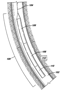
[0025] Fig. 1 illustrates a tool string 100 that has been lowered into an
interval of a
wellbore 102. The tool string 100 is carried into the wellbore 102 by a
carrier structure
104, such as a wireline, slickline, coiled tubing, or other carrier structure.
The tool string
100 includes several components, including a first component 106 (referred to
as an
"underbalance pressure creating component") for generating a transient
underbalance
pressure condition in the wellbore 102, a second component 108 (referred to as
an
"overbalance pressure creating component") to generate a transient overbalance
pressure
condition, and a perforating gun 110 for creating perforations into
surrounding formation
112. Note that the perforating gun I 10 can be combined with either of the
underbalance
pressure creating component 106 or the overbalance pressure creating component
108. In
other implementations, the perforating gun 110 can be omitted or replaced with
another
tool.
[0026] The first component 106 can be activated first to create the
underbalance pressure
condition, followed by activating the second component 108 to create the
overbalance
pressure condition. In some scenarios, the second component 108 can be
activated while
the underbalance pressure condition is still present. Conversely, the second
component
108 can be activated first to create the overbalance pressure condition,
followed by
activating the first component 106 to create the underbalance pressure
condition. In some
scenarios, the first component 106 can be activated while the overbalance
pressure
condition is still present.
[0027] As used here, a "component" can refer to either a single module or an
assembly of
modules. Thus, for example, an underbalance pressure creating component can
include a
CA 02512480 2005-07-19
low pressure module (such as an empty chamber), a second module containing
explosive
devices, and other modules (such as connector modules to connect to other
parts of a tool
string). The modules may be separate items or integrated into a single tool.
[0028] To create an underbalance pressure condition in the wellbore interval,
the well
operator provides a control signal (which can be an electrical signal, optical
signal,
pressure pulse signal, mechanical signal, hydraulic signal, and so forth) to
cause
activation of the underbalance pressure creating component 106. Once the
underbalance
condition is created in the wellbore interval, a downhole task (such as a
perforating task)
is performed. Next, the well operator may cause the overbalance pressure
creating
component 108 to generate an overbalance condition in the wellbore interval.
The
overbalance condition may cause creation of a sufficient pressure to cause
fracturing or
other stimulation of the surrounding formation (such as after perforation
tunnels have
been extended by the perforating gun 110 into the formation 112).
[0029] Although the following describes some specific embodiments of
components, the
present invention can use other components and methods to achieve the desired
result.
Fig. 2 illustrates a component 200 that is usable with the tool string 100
depicted in Fig.
1. The component 200 can be any of a selected one of the component 106, 108,
or 110 in
the tool string 100 of Fig. 1. The component 200 includes an upper head
assembly for
attaching to another part of the tool string above the component 200, and a
lower head
assembly 204 for attaching the component 200 to a portion of the tool string
below the
component 200. Between the upper and lower head assemblies 202 and 204 is
attached a
carrier 206.
[0030] The carrier 206 is a hollow housing that is capable of receiving either
a propellant
loading tube 208 or a standard loading tube 210. The standard loading tube 210
is
capable of carrying shaped charges that are mounted at positions corresponding
to
openings 212 in the loading tube 210. When activated, the shaped charges cause
perforating jets to fire through respective openings 212. In the illustrated
embodiment,
the loading tube 210 has a generally cylindrical shape. In other embodiments,
the loading
tube 210 can have other shapes, including non-cylindrical shapes.
6
CA 02512480 2005-07-19
[0031 ] The propellant loading tube 208 is a propellant pre-cast to a
cylindrical shape
(according to one example implementation) or another shape. The propellant has
cavities
for receiving shaped charges 214. Thus, in effect, the propellant is a loading
tube that has
cavities for carrying shaped charges 214. In such an arrangement, the loading
tube is
formed of the propellant instead of more conventional metal housings. If the
propellant
loading tube 208 is provided in the carrier 206, then firing of the shaped
charges 214 also
causes activation of the propellant. Burning of the propellant causes high
pressure gas to
build up.
[0032] In operation, a detonating cord (or other type of detonator) is
ballistically coupled
to the shaped charges 214 of the propellant loading tube 208. The detonating
cord or
other detonator is also ballistically coupled to the propellant. A firing head
causes
initiation of the detonating cord (or other detonator) which in turn causes
initiation of the
propellant and the shaped charges 214. The shaped charges 214, once fired,
shoots out
perforating jets that blast corresponding holes through the carrier 206. The
perforating
jets extend through any casing or liner that lines the wellbore 102, and
further extends
perforations into the surrounding formation 112. At this time, after firing of
the shaped
charges 214, the propellant continues to burn, which causes buildup of high
pressure gas
in the wellbore interval. The buildup of high pressure gas causes an
overbalance
condition to be created in the wellbore interval.
[0033] The burning of the propellant can cause pressure to increase to a
sufficiently high
level to fracture the formation. The fracturing allows for better
communication of
reservoir fluids from the formation into the wellbore or the injection of
fluids into the
surrounding formation.
[0034] In an alternative embodiment, instead of shaped charges 214 that can
extend
perforating jets through surrounding casing/liner and formation, smaller
shaped charges
can be used that have sufficient energy to blow holes through the carrier 206
(but does not
cause the perforation of the surrounding casing/liner in formation). In this
case,
perforations are not created in the formation 112-instead, openings are
created in the
carrier 206 to enable burning of the propellant to cause buildup of pressure
to achieve an
7
CA 02512480 2005-07-19
overbalance condition. In this alternative embodiment, the shaped charges are
referred to
as "punchers" or "puncher charges" since the charges are able to punch through
the
carrier 206 without cutting through the surround liner or casing.
[0035] Shaped charges in the standard loading tube 210 are similarly activated
by a
detonating cord or other detonator to cause generation of perforating jets
that extend
through the openings 212 of the loading tube 210. The perforating jets also
create
openings in the carrier 206. The difference is that a propellant is not burned
in the
standard loading tube 210 so that buildup of gas pressure does not occur with
the
activation of the shaped charges in the loading tube 210.
[0036] Fig. 3 illustrates a different arrangement of a perforating gun 300,
which can be
used as perforating gun 110 in Fig. 1. The perforating gun 300 includes a
carrier strip
302 on which are mounted shaped charges 304. As depicted, the shaped charges
304 are
arranged in a spiral pattern. A detonating cord 306 extends along the length
of the
perforating gun 300 in a generally spiral path to enable the detonating cord
306 to be
ballistically connected to each of the shaped charges 304.
[0037] In the embodiment of Fig. 3, the shaped charges 304 are capsule shaped
charges,
which include sealed capsules for housing a shaped charge within each sealed
capsule.
The capsule shaped charges 304 do not have to be carried within a sealed gun
carrier
housing (such as carrier 206 in Fig. 2), but rather, the capsule shaped
charges can be
exposed to wellbore fluids.
[0038] In addition, propellant elements 308 in the form of inserts are
provided in spaces
available between capsule shaped charges 304 and around capsule charges 304.
The
propellant elements 308 are initiated in response to a detonation wave
traveling through
the detonating cord 306. Here again, activation of the shaped charges 304 also
causes
activation of the propellant inserts 308 to cause buildup of high pressure gas
and creation
of an overbalance condition in the wellbore interval.
[0039] Fig. 4 illustrates a tool string according to another embodiment of the
invention.
The tool string 400 of Fig. 4 includes several sections 402A, 402B, 402C,
402D, and
8
CA 02512480 2005-07-19
402E. The section 402A includes a control module 404, and a gun and propellant
module
406. The gun and propellant module 406 includes both shaped charges and
propellant
elements. For example, the gun and propellant module 406 can either be the
perforating
gun 300 of Fig. 3 or the propellant loading tube 208 installed in the carrier
206 of Fig. 2.
[0040] The second section 402B includes a control module 408 and a perforating
gun
410. In the second section 402B, a propellant is not provided. However, the
perforating
gun 410 can be designed to have a relatively large amount of empty space
within the
perforating gun 410. The empty space (space other than the shaped charges, the
main
core, and other components of the perforating gun 410) is initially sealed
from the
wellbore pressure. Upon firing of the shaped charges, openings are formed in
the sealed
housing of the perforating gun 410. Following shaped charge detonation, hot
detonation
gas fills the internal chamber of the gun 410. If the resultant detonation gas
pressure is
less than the wellbore pressure, then the cooler wellbore fluids are drawn
into the gun
housing. The rapid acceleration through perforation openings in the gun
housing breaks
the fluid up into droplets and results in rapid cooling of the gas. Hence,
rapid loss of
pressure in the gun that results in rapid wellbore fluid drainage causes a
drop in the
wellbore pressure. The drop in wellbore pressure creates the underbalance
condition in
the desired wellbore interval.
[0041 ] The next section 402C in the tool string 400 includes a control module
412 and a
gun and propellant module 414. The gun and propellant module 414 can be
similar to the
gun and propellant module 406 (containing shaped charges that can extend
perforations
into surrounding formation) or the gun and propellant module 414 can include
smaller
shaped charges that are designed to blow openings through the housing of the
module 414
but do not have sufficient energy to extend perforations into surrounding
formation.
[0042] The next section 402D of the tool string 400 includes a control module
416 and a
gun module 418. The gun module 418 can be similar to the gun module 410. The
other
section 402E includes a control module 420 and a gun and propellant module
422, which
also includes both shaped charges and propellant elements. Note that sections
402A,
402C, and 402E when activated causes the creation of overbalance conditions in
wellbore
9
CA 02512480 2005-07-19
intervals proximal respective sections 402A, 402B, and 402C. Each of the
sections 402B
and 402D is able to cause creation of an underbalance conditions in wellbore
intervals
proximal the sections.
[0043] The order of the modules illustrated in Fig. 4 is provided for the
purpose of
example. In other implementations, other orders of the modules can be
employed. Also,
the order in which the modules are activated can also be controlled by the
well operator.
Activation of each section 402 is controlled by a respective control module.
In some
implementations, each of the control modules can include a timer that, when
activated,
causes a delay of some preset period before activation of the section.
[0044] Fig. 5 is a timing diagram illustrating a sequence of transient
pressure conditions
generated by activation of different modules of a tool string (such as tool
string 400 of
Fig. 4 or tool string 100 of Fig. 1) in the wellbore interval. According to
Fig. 5, a
perforating gun is first fired (which initially causes a relatively small
transient
overbalance condition 450 to be generated in the wellbore interval). The
pressure then
drops back to the normal pressure of the wellbore, which due to existence of
the
perforations in the surrounding formation is at the formation pressure.
[0045] Next, if a propellant has been initiated, then a larger overbalance
condition 452
(having higher pressure than overbalance condition 450) is generated. After
burning of
the propellant, the pressure drops back down to the normal wellbore pressure.
Next, a
perforating gun that includes a module for creating a transient underbalance
condition is
activated, which causes a transient underbalance condition 454 to be
generated. The
module can be a hollow carrier that contains low pressure gas that when opened
(such as
by firing of shaped charges) causes surrounding pressure to drop (as discussed
above).
After activation of this module, the wellbore pressure returns to close to the
normal
wellbore pressure. Next, in response to initiation of another propellant, a
transient
overbalance condition 456 is created in the wellbore interval. Thus, in Fig.
5, the
sequence of overbalance and underbalance conditions is as follows: first
overbalance,
second overbalance, underbalance, and third overbalance.
CA 02512480 2005-07-19
[0046] Fig. 6 shows another sequence of overbalance and underbalance
conditions. After
the first initiation of a perforating gun that is associated with an
underbalance pressure
creating module, a transient underbalance condition 460 is created. Next,
after the
wellbore interval has returned to the normal wellbore pressure, a propellant
is activated to
create an overbalance condition 462. Subsequently, additional underbalance
conditions
464 and 468 and overbalance conditions 466 and 470 are created.
[0047] Fig. 7 shows yet another sequence of underbalance conditions and
overbalance
conditions. Note that Figs. 5-7 show some example sequences. Many other
sequences of
underbalance and overbalance conditions are possible.
[0048] The intervals among the various pressure conditions illustrated in
Figs. 5-7 can be
on the order of milliseconds, seconds, or even minutes apart if timers are
provided in
tools according to some embodiments. If timers are not provided, then the
intervals
among the various pressure conditions in Figs. 5-7 can be on the order of
microseconds.
[0049] Fig. 8 illustrates a tool for creating an underbalance condition, in
accordance with
an embodiment. Note that the tool of Fig. 8 can be used as part of the tool
string
illustrated in Fig. 1. The Fig. 8 tool includes an atmospheric container 510A
used in
conjunction with a perforating gun 530. In the embodiment of Fig. 8, the
container 510A
(which can be expendable in one implementation) is divided into two portions,
a first
portion above the perforating gun 530 and a second portion below the
perforating gun
530. The container 510A contains a low-pressure gas (e.g., air, nitrogen,
etc.) or other
compressible fluid.
[0050] The container 510A includes various openings 516A that are adapted to
be opened
by an explosive force, such as an explosive force due to initiation of a
detonating cord
520A or detonation of explosives connected to the detonating cord 520A. The
detonating
cord is also connected to shaped charges 532 in the perforating gun 530. In
one
embodiment, as illustrated, the perforating gun 530 can be a strip gun, in
which capsule
shaped charges are mounted on a carrier 534. Such a perforating gun 530 is
also referred
11
CA 02512480 2005-07-19
to as a capsule perforating gun. In alternative embodiments, the shaped
charges 532 may
be non-capsule shaped charges that are contained in a sealed container.
[0051 ] The openings 516A, in alternative embodiments, can include a valve or
other
element that can be opened to enable communication with the inside of the
container
510A. Once opened, the openings 516A cause a fluid surge into the inner
chamber of the
atmospheric container 510A.
[0052] The fluid surge can be performed relatively soon after perforating. For
example,
the fluid surge can be performed within about one minute after perforating. In
other
embodiments, the pressure surge can be performed within (less than or equal
to) about 10
seconds, one second, or 100 milliseconds, or 10 milliseconds, as examples,
after
perforating. The timing delay can be set by use of a timer in the tool.
[0053] Referring to Fig. 9, yet another embodiment for creating an
underbalance
condition during a perforating operation is illustrated. A perforating gun 700
includes a
gun housing 702 and a carrier line 704, which can be a slickline, a wireline,
or coiled
tubing. In one embodiment, the perforating gun 700 is a hollow carrier gun
having
shaped charges 714 inside a chamber 718 of a sealed housing 716. In the
arrangement of
Fig. 9, the perforating gun 702 is lowered through a tubing 706. A packer (not
shown)
can be provided around the tubing 706 to isolate an interva1712 in which the
perforating
gun 700 is to be shot (referred to as the "perforating interval 712"). A
pressure Pw is
present in the perforating interva1712.
[0054] During detonation of the shaped charges 714, perforating ports 720 are
formed in
the housing 702 as a result of perforating jets produced by the shaped charges
714.
During detonation of the shaped charges 714, hot gas fills the internal
chamber 718 of the
gun 716. If the resultant detonation gas pressure, PG, is less than the
wellbore pressure,
Pw, by a given amount, then the cooler wellbore fluids will be drawn into the
chamber
718 of the gun 702. The rapid acceleration of well fluids through the
perforation ports
720 will break the fluid up into droplets, which results in rapid cooling of
the gas within
the chamber 718. The resultant rapid gun pressure loss and even more rapid
wellbore
12
CA 02512480 2005-07-19
fluid drainage into the chamber 718 causes the wellbore pressure Pw to be
reduced.
Depending on the absolute pressures, this pressure drop can be sufficient to
generate a
relatively large underbalance condition (e.g., greater than 2000 psi), even in
a well that
starts with a substantial overbalance (e.g., about 500 psi). The underbalance
condition is
dependent upon the level of the detonation gas pressure PG, as compared to the
wellbore
pressure, Pw.
[0055] When a perforating gun is fired, the detonation gas is substantially
hotter than the
wellbore fluid. If cold wellbore fluids that are drawn into the gun produce
rapid cooling
of the hot gas, then the gas volume will shrink relatively rapidly, which
reduces the
pressure to encourage even more wellbore fluids to be drawn into the gun. The
gas
cooling can occur over a period of a few milliseconds, in one example.
Draining
wellbore liquids (which have small compressibility) out of the perforating
interva1712
can drop the wellbore pressure, Pw, by a relatively large amount (several
thousands of
psi).
[0056] In accordance with some embodiments, various parameters are controlled
to
achieve the desired difference in values between the two pressures Pw and PG.
For
example, the level of the detonation gas pressure, PG, can be adjusted by the
explosive
loading or by adjusting the volume of the chamber 718 or adjusting the area of
opening(s)
into the chamber 718. The level of wellbore pressure, Pw, can be adjusted by
pumping up
the entire well or an isolated section of the well, or by dynamically
increasing the
wellbore pressure on a local level.
[0057] Fig. 10 illustrates an embodiment of a too1600 (useable in the tool
string of Fig.
1) that can be used to generate an overbalance pressure condition for the
purpose of
stimulating a wellbore interval. The tool 600 includes a propellant 602 and a
pressure
chamber 604. The pressure chamber 604 is used to collect gas byproducts
created by
initiation of the propellant 602. The too1600 further includes a rupture
element 606 (e.g.,
rupture disk) at one end of the pressure chamber 604. The tool 600 also
incudes a vent
sub 608 attached to the pressure chamber 604. The vent sub 608 includes
multiple
openings 610.
13
CA 02512480 2005-07-19
[0058] In operation, upon initiation of the propellant 602, high-pressure gas
is collected
in the pressure chamber 604. When the pressure in the pressure chamber 604
reaches a
sufficiently high level, the rupture element 606 is ruptured. Upon rupture of
the rupture
element 606, the gas pressure in the pressure chamber 604 is released through
the
openings 610 of the vent sub 608.
[0059] The rupture element 606 is designed to rupture at a predetermined
pressure, such
as when '/2, 3/4, or some other fraction of the propellant 602 is consumed.
The rupture
pressure can be varied by changing the number of rupture disks used in the
rupture
element 606. By employing the tool 600 according to some embodiments, the
pressure
pulse that is applied to the surrounding formation can be controlled. This
control can also
be achieved by varying the volume of the pressure chamber 604, and/or by
varying the
area of the openings 610 in the vent sub 608. A reservoir of high-pressure gas
is thus
provided by the pressure chamber 604 and released in a controlled manner to
the
surrounding formation through the vent sub 608. In this manner, by controlling
the
release of high-pressure gas, damage to the surrounding formation due to
unpredictable
high pressure applied against the formation.
[0060] While the invention has been disclosed with respect to a limited number
of
embodiments, those skilled in the art will appreciate numerous modifications
and
variations therefrom. It is intended that the appended claims cover such
modifications
and variations as fall within the true spirit and scope of the invention.
14