Note: Descriptions are shown in the official language in which they were submitted.
CA 02512836 2005-07-21
GARMENT HAVING IlVIPROVED CONTACT AREAS
BACKGROUND OF THE INVENTION
Field of the Invention
[01l The present invention relates to a garment having improved contact areas
and, more
specifically, to a garment which includes one or more relatively high-friction
areas to resist
sliding of, for example, protective pads worn over the garment.
Description of the Related Art
[02] Many different athletics and activities require that a participant wear
protective pads.
For example, football, lacrosse and hockey players and participants in other
contact sports, as
well as baseball umpires, wear elaborate padding systems under their uniforms.
Similarly,
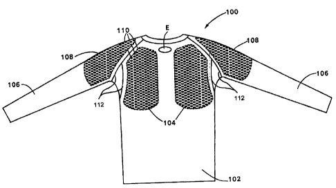
soldiers and other security personnel often wear body armor. Protective pads
of all types are
generally at least partially made of plastic for strength and lightness, but
may be
uncomfortable when worn next to a user's bare skin because of the plastic's
stiffness and lack
of breatheability. Also, ambient conditions may cause a user to desire an
extra layer of
clothing, which commonly must not alter the outside appearance of the user's
uniform. For
at least these reasons, it is common for users to wear clothing underneath
protective pads.
[03] Recently, many manufacturers have marketed specialty underclothing for
use
underneath protective pads. This underclothing is often made of a synthetic
material
designed to reduce chafing from the plastic of the protective pads and to
quickly wick away
perspiration from the user's skin to keep the user dry. However, such
synthetic material often
has a smooth or even somewhat slippery texture and hence a very low
coefficient of friction
when contacting protective pads. Consequently, the protective pads may shift
or slide from a
desired position during rigorous use (such as during a football game) and
therefore might fail
to protect the user's body.
-1-
CA 02512836 2005-07-21
[04] An example of a system for securing apparel to protective equipment is
disclosed in
U.S. Application Publication No. 2003/0115663, to Turner et al. (hereafter
referenced as
`663). Unlike the present invention, the `663 system is intended to prevent
relative
movement between outer apparel and underlying protective pads. However, even
if the `663
apparel were located between the user's body and outer protective pads,
several undesirable
effects would occur.
[051 First, the `663 system uses patches of hooked material (e.g., hook-side
VELCRO ) to
secure the protective pads, with the hook-side patch attached to the
protective pad. The `663
hook-side patch of the protective pads mates with loops formed on the apparel.
Therefore,
protective pads must be adapted to work with the `663 system, and a user
accordingly must
take the time and effort to prepare equipment for use with the `663 system
before achieving
the non-slip benefits of the system. Also, if the `663 system were adapted as
suggested
above, the hooks of the hook-side patch might protrude through the material of
the user's
undergarment and scratch the user or opponent.
[06] Second, while apparel, such as a football jersey, is generally relatively
inexpensive
and personal to one user, protective pads are much more expensive and might be
shared by
different users or borrowed for a game or for a season from a common pool,
such as from a
sports rental office. Therefore, the user is inconvenienced by having to
remove the `663
hook-side patch from the protective pads to return the borrowed pads to their
original
condition if such is a requirement of the loan. Moreover, the `663 hook-side
patches may be
attached with single-use adhesive, which would require the user to purchase
additional `663
hook-side patches or use inconvenient and messy replacement glues when using
the hook-
side patches of the `663 system with multiple sets of protective pads.
[07] Finally, the `663 hook-side patches are made of a continuous piece of
high-density
material. Even if the protective pads themselves allowed for ventilation of
the user's skin,
-2-
CA 02512836 2005-07-21
such a continuous covering would instead promote and even trap perspiration
next to the
user's skin, thus causing user discomfort contrary to the intent of the
perspiration-wicking
undergannent.
SUMMARY OF THE INVENTION
[08] The present invention is directed to a garment including a fabric and
numerous bulge
shaped gripping members located on at least a portion of the fabric. The
gripping members
are a material that exerts a greater frictional force on an object in contact
with the gripping
members than the frictional force exerted by the fabric on the object.
Preferably, the gripping
members are oval-shaped discrete elements of material having the greater
frictional force,
and the discrete elements are each attached to the fabric which may itself be
a shirt. The
gripping members are preferably grouped into two areas on the chest area of
the shirt, and
may also be located on the sleeve and back areas of the shirt.
[09] The present invention is also preferably directed to an athletic garment
for use in
combination with protective padding. The athletic garment includes a fabric
and numerous
bulge shaped gripping members on the fabric at a location in contact with at
least some of the
protective padding. The gripping members comprise discrete elements of a
material that
exerts a frictional force on the padding that is greater than the frictional
force exerted by the
fabric on the padding. Preferably, the athletic garment is a shirt and the
protective padding is
football shoulder pads. Preferably, the gripping members are located on the
chest, arm and/or
back areas of the shirt, and are oval shaped.
[10] Features of the invention include an aesthetically pleasing and
functional garment to
be used by athletes or a user that desires to reduce sliding between the
garment and a piece of
equipment or clothing. The invention also provides breathability which adds a
new level of
comfort and utility not found in the prior art. These and other features of
the present
-3-
CA 02512836 2005-07-21
invention may best be understood with reference to the accompanying drawings
and the
detailed description of the invention.
BRIEF DESCRIPTION OF THE DRAWINGS
[11] Figs. lA-1B illustrate a garment according to an exemplary, non-limiting
embodiment
of the present invention.
[12] Figs. 2A-2C illustrate portions of a high-friction area according to an
exemplary, non-
limiting embodiment of the present invention.
[131 Fig. 3 illustrates protective pads worn with a garment according to an
exemplary, non-
limiting embodiment of the present invention.
[14] Figs. 4A-4C illustrate additional garments according to exemplary, non-
limiting
embodiments of the present invention.
[15] Figs. 5A-5B illustrate a further garment according to an exemplary, non-
limiting
embodiment of the present invention.
DETAILED DESCRIPTION OF EXEMPLARY, NON-LIlVIIT]NG EMBODIIVMNTS
OF THE INVENTION
[16] The present invention is directed to a garment which resists sliding of,
for example,
protective pads worn over the garment during use. The following description
refers to the use
of football pads in combination with the garment as an example of one
application of the
garment having improved contact areas in connection with the present
invention. However, it
will be understood that this invention may be applied to any other desirable
application such
as, but not limited to, hockey, lacrosse, body armor, and the like.
[17] Fig. lA depicts a garment 100 according to an exemplary embodiment of the
present
invention. The garment 100 includes a front portion 102, made of a first
material, and at least
one high-friction area 104 (denoted by a dashed line) disposed on front
portion 102. The
-4-
CA 02512836 2005-07-21
material may be a polyester/elastane fabric with moisture-wicking properties.
For example,
the fabric may comprise 5 oz/ydZ micro-denier polyester/elastane warp knit
tricot fabric that
will wick moisture from the body and include 76% 40 denier dull polyester and
24% 55
denier spandex knit. The high elastane content allows for proper stretch and
support. The
fabric may be a tricot construction at a 60" width. The mean warp stretch may
be 187% at 10
lbs of load, and the mean width stretch may be 90% at 10 lbs of load. This
fabric also may
have a wicking finish applied to it. Such a fabric is available from UNDER
ARMOUR .
Although this material is given as an example, it will be appreciated that
other materials
known in the art can be used.
[18) It will be appreciated that other materials may also be used such as, but
not limited to,
microfibers, including elastane, nylon, polyester, blends thereof and the
like. As shown in
Fig. lA, high-friction area 104 may comprise two sections, one section being
positioned in a
left breast area and the other section being positioned in a right breast
area. High-friction
areas 104 may be disposed on front portion 102 such that an emblem (E) can be
positioned
therebetween.
[19] In the embodiment shown in Fig. 1A, front portion 102 has high friction
areas 104
located in the upper torso area. Second portions 106, shown here as left and
right arm
portions, are attached to front portion 102. Front portion 102 may be
separated from second
portions 106 by seams 112. In this case, high-friction areas 104 on front
portion 102 are first
high-friction areas 104. Second high-friction areas 108 (denoted by a dashed
line) may be
disposed on second portions 106. The dashed lines are provided in the Figures
to more
clearly show high-friction areas 104, 108 but no visual delineation of high-
friction areas 104,
108 is required on garment 100 itself. Conversely, high-friction areas 104,
108 may
optionally be set apart from the rest of garment 100 by a different color or
material or the
like, whether for functional or aesthetic reasons.
-5-
CA 02512836 2009-01-29
[20] High-friction areas 104, 108 of the present invention are each defined by
a plurality of
gripping members or islands 110. Each of high-friction areas 104, 108 is
defined by multiple
gripping members 110, arranged in a suitable fashion. Gripping members 110 are
each made
of a flexible second material, such as, but not limited to, a tackifying ink
or the like. The
tackifying ink may be applied to garment 100 using a screen-printing process.
In any event,
the tackiness of gripping members I10 is high enough such that the padding
worn over
garment 100 does not slide off of the desired areas of contact with garment
100 and thus
create an uncomfortable situation for the user.
[21] The tackiyfying ink may be a PVC (polyvinyl chloride) based printing ink,
know as
plastisol. An example of a plastisoll ink is Ultra Gel, which is a press-ready
plastisol for
screen printing on fabrics available from Rutland, Inc. of Pineville, N.C.
Plastisol inks
usually also contain plasticizers to aid in the screen printing process.
Plasticizers are present
because PVC alone is a very rigid plastic and has to be softened or
plasticised to give it the
necessary degree of flexibility.
[22] U.S. Pat. No. 4,517,893 (Wile et al.) discloses the use of plastisols
in silk screen printing to form a tough, rubber-like film that can stretch
with
the fabric without losing its adhesion and has the further desirable quality
of being able to withstand repeated washing cycles. The use of
plastisols for screen printing is also disclosed in U.S. Pat. No. 6,780,460
(Ou-yang).
[23] The garment 100 is well suited to be worn with compression type clothing
where an
additional garment or shirt is disposed over the padding or where the padding
is secured to
the user with straps, to contain the underlying elements in a*snug, compressed
manner on a
user's body. Fig. 1B depicts a back portion 103 of garment 100 that is made of
the first
material and has a friction area 105 (denoted by a dashed line) disposed on
back portion 103.
-6-
CA 02512836 2009-01-29
Although gripping members 110 populate areas 105 and 108 entirely, only
portions of the
gripping members 110 are shown in the back view. It will be understood that
high friction
area 105 could be arranged as two high friction areas such as two high
friction areas 104.
High-friction area 105 includes a plurality of gripping members 110 that
extend across back
portion 103 in a horizontal and vertical direction. Gripping members 110 on
back portion
103 preferably form one group of equally spaced gripping members 110. However,
it will be
appreciated that the grouping or spacing may be altered to conform to the
particular needs of
a user. Additionally, an emblem (E) may be positioned among gripping members
110.
[24] Gripping members 110 of the present invention may be of any suitable size
and have
a bulged shape. For example, as shown in Fig. 2A, each gripping member 110 may
be
rounded or substantially oval-shaped. Figs. 2B and 2C illustrate additional
examples of other
non-limiting embodiments of gripping members 110 of the present invention
including
rectangular-shaped gripping members 110 or a combination of rectangular- and
round-shaped
gripping members 110. Preferably, each gripping member 110 is oval-shaped,
having a
width 212 of about 5 mm to about 10 mm, more preferably, about 6 mm to about 8
mm, and a
height 213 of about 2 mm to about 6 mm, more preferably, about 3 mm to about 4
mm. In
the event that gripping members 110 are square-shaped, gripping members 110
may be about
5mm to about 10 mm, by about 5 mm to about 10 mm, more preferably, about 6 mm
to about
8mm, by about 6 mm to about 8 mm. In the event that gripping members 110 are
circle-
shaped, the circles may have a diameter of about 5 mm to about 10 mm, more
preferably
about 6mm to about 8mm. Preferably, gripping members 110 have a flat top
surface for
gripping the protective pads, etc. Gripping member 110 preferably has a height
above the
surface of garment 100 that is about 0.5 mm to about 1.0 mm, more preferably
about 0.6 mm
to about 0.7 mm. Gripping members 110 may be of differing gripping member
sizes and
shapes varying within the gripping member sizes and shapes discussed above, or
may all be
-7-
CA 02512836 2005-07-21
the same gripping member size and shape. The gripping member sizes and shapes
may
optionally be chosen responsive to the location or position of each gripping
member 110 on
the garment. In accordance with the invention, the size, shape, and/or
position of gripping
members 110 may be determined for optimum functional and/or aesthetic results
in a given
application.
[25] In the exemplary embodiment of Fig 2A, each gripping member 110 is
preferably
separated from adjacent gripping members in the horizontal direction 214 by a
distance of
about 5 mm to about 10 mm, more preferably about 7 mm to about 9 mm. Each
gripping
member 110 is preferably separated from adjacent gripping members in the
vertical direction
216 by a distance of about 10 mm to about 20 mm, more preferably about 11 mm
to about 13
mm. High-friction areas, such as 104, 108 contain sufficient space not covered
by gripping
members 110 to allow breatheability through garment 100 and increased comfort
for the user.
[26] Gripping members 110 are positioned on an outside of the garment and are
intended
to exert a frictional force on an underside of protective pads, for example,
worn over the
garment, so as to reduce slippage between the garment and the protective pads.
Gripping
members 110 may also be positioned on an inside of the garment to exert a
frictional force to
protective pads worn under the garment, so as to reduce slippage between the
garment and
the protective pads. It will also be appreciated that gripping members 110 can
be positioned
on an inside of garment 100 to exert a frictional force directly to a user or
directly to another
layer of clothing, instead of having gripping members 110 contact the pads.
The use of a
plurality of gripping members 110 in a localized area produces multiple points
where stress
between gripping members 110 and the protective pads is increased.
[27] Fig. 3 depicts a portion of a set of protective pads 314, as commonly
used by football
players, worn over a garment 100 according to a non-limiting embodiment of the
present
invention. Protective pads 314 generally are of somewhat standard sizes and
shapes, and
-8-
CA 02512836 2005-07-21
high-friction areas 104, 108 may be designed to have a substantially similar
outline to an
outline of the corresponding portion of protective pad 314 in contact with
garment 100 and
worn to protect that area of the user's body. High-friction areas 104, 108 may
be slightly
larger than the portion of protective pads 314 in contact therewith, as shown
in Fig. 3, to
allow for slight variances in user-preferred positioning of the protective
pads 314.
[28] Garment 100 may be donned by the user as an undergarment, and then the
protective
pads 314 may be attached to the user's body atop garment 100 in a known
manner, such as
via a harness, or other strapping/positioning means. The user may optimally
wear a jersey or
other uniform component atop protective pads 314. As the user participates in
athletic
activities, protective pads 314 will tend to shift position on the user's body
because of the
user's own movements or outside forces acting on the user. Without use of the
invention,
such sliding or shifting of protective pads 314 could result in discomfort to
the user if the
movement of protective pads 314 chafes the user's skin and could result in a
failure to
provide cushioning to the desired portions of the user's body.
[29] In order to reduce or prevent sliding of protective pads 314, high-
friction areas 104,
108 exert a frictional force on protective pads 314 relative to garment 100
and thereby also
tend to keep protective pads 314 substantially in their original position on
the user's body.
Such forces counteract against outside forces that would otherwise cause
protective pads 314
to slide across the skin or non-gripping undergarment of the user. Depending
upon the
outside force and/or the relative materials of high-friction areas 104, 108
and protective pads
314, some sliding or shifting of the protective pads 314 may still occur, but
the frictional
force produced by gripping members 110 is intended to mitigate such a sliding
effect.
[30] Various garments, non-limiting examples of which are shown in Figs. 4A-
4C, may
include gripping members 110 in accordance with the present invention. Fig. 4A
depicts a
sleeveless singlet garment 400 having a torso portion 402 with a high-friction
area 404
-9-
CA 02512836 2009-01-29
disposed thereon. Fig. 4B depicts a brief-type garment 406 having torso
portion 408 with
high-friction areas 410 disposed on the sides thereof. Fig. 4C depicts a pant
garment 412
having torso portion 414 with a high-friction area 416 disposed thereon, and
having attached
thereto'second portions 418, shown as right and left leg portions, having high-
friction areas
420 disposed thereon. High friction areas 404, 410, 416 and 420 include
gripping members
110 having any of the above-noted shapes and dimensions.
[31] Figures 5A and 5B illustrate an exemplary embodiment of a garment 500
that may be
used beneath pads, such as those worn by a hockey player. High friction areas
502 are
provided in upper arm sleeve areas of garment 500 and additional high friction
areas 504 are
provided in lower arm sleeve areas of garment 500. High friction areas 502
reduce slipping
between garment 500 and pads 508 having pottions extended along the user'a
biceps (see
Figure 5B). High friction areas 504 reduce slipping between garment 500 and
pads 506
disposed in the lower arm area. The increase in friction between garment 500
and pads 506
and 508 may be further assisted by straps that compress the padded areas to
the user's arms.
[32] In an exemplary embodiment, high friction area 502 has a length of about
15 cm
to about 25 cm, more preferably, about 17 cm to about 23 cm. High friction
area 504 has
a length of about 11 cm to about 20 cm, more preferably, about 14 cm to about
17 cm.
High friction area 504 may start about 7 cm to about 15 cm from a bottom hem
514 of the
sleeve, more preferably, about 9 cm to about 12 cm from the bottom hem. High
friction area
502 may start about 1 cm to about 5 cm from a raglan under arm seam of the
sleeve, more
preferably, about 2 cm to about 4 cm from the under arm seam. It is also noted
that the
sleeves can have a seam in the lengthwise direction, and the high friction
areas 502 and 504
may be parted around the lengthwise seam so that individual gripping members
110 are
spaced about 1 cm to about 4 cm from the lengthwise seam, more preferably,
about 2 cm to
about 3 cm from the seam. As will be appreciated, high friction areas 502 and
504 include
-10-
CA 02512836 2005-07-21
gripping members 110 having any of the above-noted shapes and dimensions.
These
dimensions and positions can be varied to correspond with other types of
protective wear,
such as pads worn during lacrosse and the like. The garment 500 is accordingly
well suited
for use with padding that is strapped on a user's body to assist in
maintaining the padding in a
desired position.
[33] While aspects of the present invention have been particularly shown and
described
with reference to exemplary, non-limiting embodiments above, it will be
understood by those
skilled in the art that various additional embodiments may be contemplated
without departing
from the spirit and scope of the present invention. For example, the garment
might be only
one of several layers of underclothing worn by the user; the garment could be
worn at times
without overlying protective pads; the high-friction areas could cover
substantially the entire
garment; or the size, shape, and/or positioning of the gripping members could
be assigned
and/or marketed for use in a specific activity. However, a device or method
incorporating
such an embodiment should be understood to fall within the scope of the
present invention as
determined based upon the claims below and any equivalents thereof.
-11-