Note: Descriptions are shown in the official language in which they were submitted.
CA 02517631 2005-08-31
1
Title: SHOCK RESISTANT MOUNTING FOR SMALL DISPLAY SCREEN
[001] This specification relates to such hand-held electronic
products as cell-phones, personal digital assistants (PDAs),
cameras, etc, which include a display or video screen.
[002] One of the encountered difficulties has been that the
screen is fragile. Yet hand-held devices are very likely to be
dropped, or otherwise abused, occasionally, by the user. Although
the user might expect that (repeated) dropping will render the
product inoperable, still the prudent manufacturer seeks to make
the product as robust as possible. The technology described herein
is concerned with improvements in the manner of mounting the
screen, with the aim of reducing damage due to impacts.
[003] Providing cushions of foam material (poron) front and
back of the screen unit is effective to prevent damage from impacts
front and back. But it is when the device is dropped so that the
screen is impacted on its edge that a major potential for damage
arises. Now, the whole weight of the screen unit may be
concentrated perhaps onto one impacting corner. The glass
components of the screen unit are polarised, which exacerbates the
tendency of microcracks to propagate through the glass.
[004] Another encountered difficulty has been that of
accurately positioning the screen during production-line assembly.
Screens for hand-held devices are usually mounted in foam, for its
shock-absorbing properties, and the screen is glued to the foam.
The type of adhesive used is of the stick-on-contact type, whereby
the screen must be located to what will be its final position
before it touches the adhesive, and it is all too easy for the
screen to be slightly misaligned or misplaced. The technology
described herein is concerned with the manner in which the screen
is located and positioned just prior to contact with the adhesive
foam, with the aim of improving accuracy of positioning on a
repeatable, production-line basis.
CA 02517631 2005-08-31
2
[005] The technology described is aimed at providing a space
all around the fragile glass components of the screen unit. It is
aimed at bringing the screen unit gently to rest, within that
space, when the device is dropped. It is aimed at ensuring that
the (glass) components are protected from impacts of sufficient
violence to cause damage. And it is aimed at doing these things
repeatedly.
[006] Space inside a hand-held electronic device is at a tight
premium. It is very demanding to provide sufficient space around
the screen unit to enable the screen unit to be brought gently to
rest after an impact. If the designer also has to provide an
additional margin of tolerance, to cater for the screen unit being
inaccurately positioned, misaligned, misplaced etc, within the
space, the demands can hardly be met. The technology is aimed at
ensuring the screen unit is so accurately placed that the margin
for positional tolerance can be reduced or eliminated.
[007] LIST OF DRAWINGS:
Fig 2 is a plan view of a mounted screen assembly;
Fig 2 is a reverse plan view of the mounted screen assembly of
Fig 1, in combination with (part of) a hand-held
electronic device;
Fig 3 is an exploded view showing the components of the mounted
screen assembly of Fig 1, being the mounting frame, the
foam buffer, and the screen unit;
Fig 4 is an exploded view showing the components of the screen unit
of Fig 3, being the screen stack, the plastic shell, and
the backing plate;
Fig 5a is a diagrammatic plan view of a mounted screen assembly
similar to that shown in Fig 1;
Fig 5b is similar to Fig 5a, showing another mounted screen
assembly;
Fig 5c is similar to Fig 5a, showing a further mounted screen
assembly;
Fig 6 is a cross-section on line 6 of Fig 4 of the screen unit;
Fig 7 is a cross-section on line 7 of Fig 4 of the screen unit;
Fig 8 is a cross-section on line 8 of Fig 4 of the screen unit,
CA 02517631 2005-08-31
3
showing the screen unit in position just prior to its
final assembly into the mounting frame;
Fig 9 is similar to Fig 8, but shows the screen unit finally
assembled into the mounting frame, forming the mounted
screen assembly;
Fig 10 is the same view as Fig 9, but includes components of the
electronic device;
Fig 11 is similar to Fig 9, but shows the screen unit moved hard
over to the left, within the mounting frame.
[008] The apparatuses shown in the accompanying drawings and
described below are examples. The scope of the patent protection
sought is defined by the accompanying claims, and not necessarily
by specific features of exemplary embodiments.
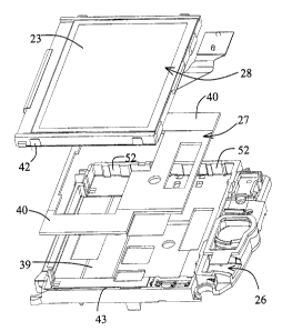
[009] The apparatus shown in Fig 1 is a mounted screen assembly
20, having a display screen 23. Fig 2 shows the (back of the)
mounted screen assembly 20, assembled into the casing 24 of a PDA,
and secured rigidly to the casing by means of four bolt-down
fittings 25.
[0010] Fig 3 shows the components of the mounted screen assembly
20. These are (a) a mounting frame 26, comprising a plastic
moulding; (b) a foam buffer 27, comprising a punched-out sheet of
plastic resilient porous foam; and (c) the screen unit 28.
[0011] Fig 4 shows some of the components of the screen unit 28.
These are (a) the display stack 29, which comprises a stack of
layers, the topmost of which is the display screen 23 itself; (b) a
shell 30, comprising a plastic moulding; and (c) a backing plate
32. The backing plate 32 is bent and folded from a sheet of
stainless steel, and incorporates a polished reflector surface 34.
[0012] The several layers that make up the display stack 29 are
a tight fit between the ledged sides 35 of the moulded shell 30.
The metal backing plate 32 is crimped to the shell 30, whereby,
together, the stack 29, the shell 30, and the backing plate 32
constitute the integrated screen unit 28, being the structure that
CA 02517631 2005-08-31
4
is to be protected from impacts.
[0013] The crimping involves the provision of shaped recesses 36
in the plastic shell 30, and the provision of tags 37 in the
upstanding metal rim 38 of the backing plate 32. Fig 6 shows a
cross-section of the screen unit in the area of the crimps, and
Fig 7 is a cross-section away from the crimps.
[0014] The crimped screen unit 28 can now be assembled, as a
rigid unified single component, into the mounting frame 26. The
underside of the foam sheet 27 is pre-glued on top of the baseplate
39 of the mounting frame 26. The foam sheet 27 is provided, on its
upper side, with stripes 40 of adhesive. The adhesive in the
stripes 40 is protected by covering strips (not shown), the strips
being peeled off just prior to the backing plate 32 being lowered
down into touching contact with the adhesive.
[0015] The manner of assembly is shown in Figs 8 and 9. In
Fig 8, the springy tabs 42 protruding from the backing plate 32 of
the screen unit 28 engage with, and rest on, the lips 43 of the
plastic mounting frame 26, whereby the screen unit 28 is held
slightly separated from, and just clear of, the (exposed) adhesive
stripes 40. Fig 9 shows the screen unit 28 having been pressed
down until the underside of the backing plate 32 contacts the
stripes 40. After that, the screen unit 28 remains firmly adhered
to the mounting frame 26.
[0016] The now-completed mounted screen assembly 20 can now be
bolted into the casing 24, as described. Fig 10 shows some of the
other components of the device, in side cross-section. The circuit
board 45 and other components are housed inside the casing.
[0017] The manner in which the screen unit 28 is fixed into the
casing of the PDA may be contrasted with the manner in which that
task has been done in the conventional designs. The differences
attributable to the provision and function of the springy tabs 42
will now be described.
CA 02517631 2005-08-31
[0018] one of the problems with a hand-held electronic device is
that such devices are prone to being dropped. In fact,
manufacturers have a program of drop tests; typically, the devices
are classed as being robust enough and sturdy enough if, in e.g
eighty percent of the devices, when the devices are dropped from a
height of so many feet onto a concrete floor, the screen remains
intact and functioning. The drop test may specify that the device
be dropped so that it lands on one corner, and/or lands flat-on,
etc.
[0019) The conventional designs have tended to perform only
modestly in these drop tests. Of course, it is always possible to
protect the screen more effectively from such abuse -- but not,
hitherto, without substantial compromises and penalties by way of
extra cost, extra weight, and extra occupied space -- the latter
being perhaps the most acute.
[0020] It should be noted that the trend, in PDA and cell phone
design, has been to add more and more features of performance,
increasing the demand for premium space inside the casing, and yet
at the same time the designer is pressured to reduce the overall
size of the product. In some respects, continuing engineering
improvement has meant that components do improve in terms of the
compromise between cost, size, weight, robustness, etc, and
performance features. However, the pressure in the direction of
improving resolution, increasing screen size, colour, brightness,
etc, tends to render the latest screens, if anything, less rather
than more robust.
[0021] One of the difficulties is that the display screen
includes polarised glass, which is inherently more prone to the
propagation of micro-cracks than is ordinary glass, and therefore
inherently less able to stand up to drop tests.
[0022] The springy tabs 42 assist in protecting the fragile
screen unit 28 from the violence of the drop test. Fig 11 shows
the effect on the screen unit of the device striking a hard object
to the left side. By its inertia, the screen unit 28 surges
CA 02517631 2005-08-31
6
leftwards, within the mounting frame 26. The foam material 27
deflects in a shear mode, as shown. The left side springy tab 42L
becomes compressed while the right side springy tab 42R relaxes.
These strains -- in the springy tabs and in the foam -- absorb the
energy of the impact, allowing the screen unit to come gently to
rest, under controlled deceleration, before the screen unit can
impact against anything hard and rigid.
[0023] It may be noted that, even if the impact should carry the
screen unit 28 even further to the left than is shown in Fig 11,
the springy tab 42L can deflect a little further (although now with
an increased spring-rate), in that the root area 46 of the backing
plate 32, at the base of the springy tab 42L, can undergo (slight)
twisting and curling, without the backing plate (or anything else)
taking a permanent set. Thus, even after an impact that takes the
screen unit 28 even further to the left than is shown in Fig 11,
with the resulting further distortions of the backing plate itself,
immediately after the impact the backing plate and the other
components revert to their Fig 9 / Fig 10 positions.
[0024] The springy tabs should not be so stiff, of course, that
the impact of the tabs themselves puts such a large deceleration
into the screen unit as to damage it. Equally, the springy tabs
should not be so flimsy that they do not properly inhibit the
screen unit from impacting into the mounting frame.
[0025] It is suggested that the impact absorbing function is
adequate when the permitted travel of the screen unit, between the
Fig 9 position and the Fig 11 position, is at least about one-
quarter-millimetre, and preferably a half-millimetre or more. At
least from the standpoint of impact absorption, the larger the
permitted deflection of the springy tab, the better.
[0026] Preferably also, the spring-rate of the springy tab
should be such that the force required to cause the screen unit to
move to the Fig 11 position is about twenty and preferably thirty
times the weight of the screen unit. It is suggested that the
springy tab would be too stiff if it took more than about thirty
CA 02517631 2005-08-31
7
and preferably forty-five times the weight of the screen unit to
move the screen unit to Fig 11, and that the springy tab would be
too flimsy if it took less than about ten and preferably fifteen
times the weight of the screen unit to move the screen unit to
Fig 11.
[0027] As to dimensions, good results (that is to say, a
significant reduction in the number of failures in drop tests) have
been obtained, with a screen unit weighing twenty-five grams, when
the stainless steel backing plate 32 (and therefore the tab 42) has
a thickness of 0.2 mm, and where two tab elements per side have a
length (height) of 3.5 mm, and each a width of 3.5 mm. (Thus, a
single springy tab having the same impact-cushioning effect as
those two tab elements would have a width of seven mm.) It is
suggested that the acceptable limits of spring rate of the springy
tabs may be set at between one half and double the spring rate of
tabs having these dimensions.
[0028] It has been mentioned above that the springy tabs 42
enable the screen unit 28 to be positioned accurately, with respect
to the mounting frame 26, just before the screen unit 28 is pressed
down into final contact with the adhesive stripes 40. Further
consideration will now be addressed to this point.
[0029] In the conventional designs, it has been quite difficult
to position the screen unit accurately within the mounting frame,
on a production-line basis. Especially when the screen unit is
assembled automatically, there is little opportunity for the screen
unit to be unglued and repositioned, if it is misaligned. The
misalignment would not be picked up until final (human) inspection.
It may be noted that even the smallest angular misalignment can
hardly be permitted. If the screen is even slightly perceptibly
misaligned or crooked, relative to the casing aperture, even though
such misalignment would have no effect on useability, still a user
would usually interpret the misalignment as irritating evidence of
general low quality in the product.
[0030] Similarly, when the screen unit is assembled manually
CA 02517631 2005-08-31
8
into the mounting frame, while it is possible that the operator
might make an attempt to re-position a misaligned screen unit, in
practice that cannot be relied on. For manual assembly, the
designer would provide a support edge or the like against which the
operator can rest the screen unit, just prior to lowering the unit
carefully down onto the adhesive. However, providing a support
edge, e.g on a production jig, is not preferred.
[0031] Thus, however the assembly was done, it was difficult to
ensure that the screen unit was positioned properly, repeatedly, on
the production line. By contrast, as described herein the screen
unit 28 lies perfectly positioned, but clear of the adhesive 40, as
in Fig 8, just before the screen unit is pressed against the
adhesive. The production line operative can achieve hitherto
unachievable accuracy, repeatable, with very little care,
attention, or skill.
[0032] Not only should the screen unit be free of any degree of
angular misalignment, the screen unit also should not be misplaced
laterally, i.e more to the left than to the right. The Fig 8 /
Fig 9 assembly manner ensures that both angular misalignments and
translational misplacements are reduced to an imperceptible
minimum.
[0033] It is stressed that this degree of repeatable accurate
positioning does not require placing the screen unit against some
solid abutment, as a positioning datum -- which might leave the
screen unit vulnerable to impacts against that solid abutment.
After assembly, the screen unit 28 is able to move in all modes and
directions in response to impacts, and to be decelerated in all
those modes by the springy tabs, and by being surrounded by foam.
The key direction in which impacts do the most damage is when the
direction of the impact lies in the plane of the screen 23, and
that is when the springy tabs 42 and adhesives 40 function most
effectively.
[0034] A front layer 47 of foam is glued to the casing 24, and
surrounds the aperture 48 in the casing 24. This foam may or may
CA 02517631 2005-08-31
9
not be adhesively secured to the margins of the screen unit. It
may happen that, for service purposes, it is desired to change e.g
the screen unit 28. In that case, the adhesive 40 on the foam that
secures the screen unit to the foam should be of the kind that
permits separation. The adhesive that secures the foam to the
casing should be of the more permanent type.
[0035] Mounted as shown, the screen unit 28 is very well
protected against impacts. It has often been the case
conventionally that a glass cover or lens was placed over the
actual display screen, for physical protection. The designer could
arrange that it was the glass lens, and not the glass components of
the screen unit, that struck the casing during an impact, and this
arrangement did provide effective mechanical protection.
[0036] The disadvantages with the use of a lens, apart from
extra space, weight, and cost, are that the lens interferes with
light transmissibility, which can be critical especially when the
screen is in reflective, rather than back-lit, mode. Battery life
is critical in PDAS, whereby the designer arranges to maximise the
time spent in reflective mode, whereby the time spent in back-lit
mode is minimised. The provision of the springy tabs is useful in
enabling the mounted screen unit to be properly resistant to impact
damage, without the need to resort to a covering lens.
[0037] It should be understood that it is the combination of the
springy tabs with the foam cushions that is effective to protect
the screen unit from impacts. It is not suggested that the springy
tabs would be sufficient, on their own (i.e without the foam
cushions), in most cases, to properly protect the screen unit. In
the type of edge-impact as illustrated in Fig 1l, the foam material
(and the adhesive) is stressed in shear, and thus the foam absorbs
a good fraction of the impact energy. Similarly, just the foam on
its own gives barely adequate protection, as experience has shown.
[0038] On the other hand, it can be worth including the springy
tabs even in a case where the extra impact resistance is really not
required. That is to say, the other function of the springy tabs
CA 02517631 2005-08-31
can be important, in that the springy tabs assist in locating the
screen unit in exactly the right position just prior to pressing
the screen unit down onto the adhesive. This function would be
useful even if the screen unit were glued directly to the casing,
rather than to the foam cushion -- although, of course, screen
units are almost invariably mounted in foam cushions.
[0039] The expression °springy tab" as used herein refers to the
whole springy tab that is present along one side of the screen
unit. In a case where two springy tab elements are provided on the
same side, e.g two on the left side of the screen, and those two
elements are stressed in the same sense by an impact, those two tab
elements would be regarded as sub-components of one single springy
tab on the left side. As shown in Fig 5a, the screen unit has been
provided with eight springy tab elements, two each side; elements
49T on the top, 49B on the bottom, 49L on the left, and elements
49R on the right.
[0040] It is not necessary to provide eight tab elements in
every case, however. As shown in Fig 5b, only four tab elements
are provided, two 50L to the left and two 50R to the right sides,
and none to the top and bottom sides. (Fig 5b corresponds to the
components shown in Fig 4 in this respect.) Now, in order to hold
the screen unit restrained against top/bottom impacts, the Left and
right tab elements should be tight laterally, i.e tight in the
top/bottom direction, in their sockets 52 in the mounting frame.
It has been found that the springy tabs, when tight in their
sockets, have a more or less similar resilience in the top/bottom
direction as they have in the left/right direction. It is not
necessary that all four tab elements be a tight fit in their
respective sockets.
[0041] In Fig 5c, the number of springy tabs 53L,53R has been
reduced to two. This of course is the minimum. Four is preferred
(Fig 5b), as giving a rather greater degree of resistance to the
type of impact that causes the screen unit to rotate in the plane
of Fig 5b. Sometimes the designer has less space in which to place
the springy tabs on the top and bottom edges rather than on the
CA 02517631 2005-08-31
11
left and right edges, because of the other components (e.g wiring
ribbons, etc) associated with the top and bottom, whereby the
Fig 5b arrangement again is preferred.