Note: Descriptions are shown in the official language in which they were submitted.
CA 02523267 2005-10-21
WO 2004/094823
PCT/US2004/012797
HYDRAULICALLY ACTUATED PUMP FOR LONG DURATION
MEDICAMENT ADMINISTRATION
BACKGROUND OF THE INVENTION
The systems and methods described herein relate to a hydraulic pump system
that can be used in medicament pumps for injectibles, specifically to low-
cost,
miniature, single-use pump systems.
Various people, such as diabetics, people require continuous or near
continuous infusion of certain drugs or medicines (broadly referred to herein
as
medicaments).
Many attempts have been made to provide continuous or near continuous
dosing of medicaments, such as insulin, using pump systems. For example, one
known pumping technique uses gas generated by various means to advance a
plunger in a syringe, thereby injecting the medicament through an infusion
set. The
infusion sets is a means for conveying medicament through the patient skin and
may
comprise a standard needle, a microneedle, a microneedle array, and a catheter
and
cannula system.
Although these systems can work quite well, patients using these systems,
particularly in continuous dose mode, need to monitor closely or deactivate
these
devices under circumstances where the ambient air pressure may vary greatly,
such
as in an airplane. In particular, patients need to be careful that the
infusion pump
does not deliver a dangerously increased dosage in airplanes at high
altitudes, where
the ambient pressure is significantly reduced.
What is needed is a simple, inexpensive, single-use only medicament pump
system. Such a system must have the capacity to provide variable dosing under
patient control as well as safety and consistency in the metered dose at any
range of
ambient pressures or operating conditions.
CA 02523267 2005-10-21
WO 2004/094823
PCT/US2004/012797
SUMMARY
In an exemplary embodiment, the systems described herein include, inter
alia, a pump device, which may be single use, and that that provides for
sustained
low volume (preferably high potency) medicament application, such as for use
by
insulin-dependent diabetics and other patients. The pump may employ as an
actuator
a spring-compressed bellows crank, hinged plate, paired roller set, or other
peristaltic mechanisms to force a volume of hydraulic fluid through a flow
restrictor, such as an aperture, thereby expanding one chamber of a two
chamber
hydraulic cylinder. The second, fluid storage chamber, containing a
medicament, is
vented through a conventional orifice as the hydraulic chamber is expanded by
introduction of additional hydraulic fluid. The medicament thus expelled may
then
be injected or infused into a patient via any suitable injection and/or
infusion
mechanism.
The restrictor, in one embodiment, may be a hydraulic fluid aperture and may
- 15 be a fixed micro-aperture of approximately 0.1 - 10 pm in diameter, or
about 1-5 in
in diameter, and one ten-thousandths of an inch (0.0001", or about 2.5 pm) in
diameter. In another embodiment, the hydraulic fluid aperture may be an
adjustable
aperture providing either continuous or step-wise diameter variations of
approximately 0.1 - 10 m in diameter, or about 1-5 1.1m in diameter,
preferably one
ten-thousandths of an inch (0.0001", or about 2.5 in) in diameter. Combined
with a
hydraulic fluid of appropriate viscosity, the micro-aperture provides precise
pressure
regulation that is insensitive to ambient pressure or other environmental
conditions.
This insensitivity, in turns, allows for highly accurate dosing and dose
regulation
under a wider range of conditions than previously seen in the arts.
Thus one aspect of the invention provides a hydraulically actuated fluid
delivery system for sustained delivery of a liquid component, comprising: a
pump
chamber, and a fluid storage chamber having an orifice and being functionally
connected to said pump chamber by a moveable barrier; a hydraulic fluid
reservoir
for storing a high viscosity fluid, said reservoir being connected to said
pump
chamber via a restrictor, such as an aperture, which may be less than 10 pm in
-2 -
CA 02523267 2005-10-21
WO 2004/094823
PCT/US2004/012797
diameter, and the largest insoluble particle, if any, in said hydraulic fluid
may
optionally be no more than the size of said aperture; and, an actuator
functionally
connected to said hydraulic fluid reservoir to cause said hydraulic fluid to
flow into
said pump chamber through said aperture, thereby expanding the volume of said
pump chamber, displacing said moveable barrier and causing a quantity of said
liquid component stored in said fluid storage chamber to be delivered at a
sustained
rate.
In one embodiment, the pump chamber and the fluid storage chamber are
both within a compai __ talent.
In one embodiment, the moveable barrier is a piston or plunger plate.
In one embodiment, the movement of the piston or plunger plate is guided
such that the piston or plunger plate does not flip or generate leakage when
moving.
In one embodiment, the moveable barrier is one or more deformable
membrane separating the pump and the fluid storage chambers.
In one embodiment, the liquid component is a medicament, and the wall of
the fluid storage chamber is composed of bio-inert materials.
In one embodiment, the aperture has a fixed size.
In one embodiment, the aperture is adjustable in size to allow variable
hydraulic pressure.
In one embodiment, the size of the aperture is adjusted by a thumbwheel
control / dial.
In one embodiment, the thumbwheel control activates a miniaturized valve or
iris device.
In one embodiment, the quantity of said liquid component is expelled at a
rate selected from: about 100 n1 -1 piper minute, about 1-10 j.d per minute,
or about
10-100 piper minute.
-3-
CA 02523267 2005-10-21
WO 2004/094823
PCT/US2004/012797
In one embodiment, the actuator is a miniaturized bellows crank, paired
rollers, one or more piezoelectric elements, a ratchet or stepper motor driven
unit, a
two-plate hinged peristaltic mechanism, an electrically driven or
piezoelectric
mechanism.
In one embodiment, the actuator employs one or more external springs
having a constant spring coefficient over its full range of motion.
In one embodiment, the fluid delivery system further comprises a connective
passage linking the hydraulic fluid reservoir to the pump chamber through the
aperture.
In one embodiment, the liquid component is a solution of a medicament.
In one embodiment, the medicament is insulin, an opiate, a hormone, a
psychotropic therapeutic composition.
In one embodiment, the orifice of the fluid storage chamber is connected to
an infusion set for delivering the liquid component to a patient.
In one embodiment, the patient is a mammalian patient selected from human
or non-human animal.
In one embodiment, the infusion set is a needle, a lumen and needle set, a
catheter-cannula set, or a microneedle or microneedle array attached by means
of
one or more lumens.
In one embodiment, the pump is manufactured with inexpensive material for
single-use.
In one embodiment, the inexpensive material is latex-free and is suitable for
use in latex-intolerant patient.
In one embodiment, the inexpensive material is disposable or recyclable.
In one embodiment, the inexpensive material is glass or medical grade PVC.
-4 -
CA 02523267 2005-10-21
WO 2004/094823
PCT/US2004/012797
In one embodiment, the fluid delivery system further comprises a second
hydraulic reservoir.
In one embodiment, the second hydraulic reservoir is separately and
independently controlled by a second actuator.
In one embodiment, the second hydraulic reservoir and the original reservoir
are both connected via a common connective passage and through the aperture to
the
pump chamber.
In one embodiment, the second hydraulic reservoir is connected to the pump
chamber through a second aperture.
In one embodiment, one of the two hydraulic reservoirs is used for sustained
delivery of the liquid component, and the other of the two hydraulic reservoir
is used
for a bolus delivery of the liquid component at predetermined intervals.
In one embodiment, both apertures are independently adjustable.
In one embodiment, one of the two apertures are adjustable.
In one embodiment, the sustained delivery is over a period of: more than 5
hours, more than 24 hours, more than 3 days, or more than one week.
In one embodiment, the viscosity of the hydraulic fluid is at least about ISO
VG 20, or at least about ISO VG 32, or at least about ISO VG 50, or at least
about
ISO VG 150, or at least about ISO VG 450, or at least about ISO VG 1000, or at
least about ISO VG 1500 or more.
Another aspect of the invention provides a hydraulically actuated pump
system comprising: a pump chamber functionally connected to a moveable
barrier; a
hydraulic fluid reservoir for storing a high viscosity fluid, said reservoir
being
connected to said pump chamber via an aperture of less than 10 and in some
embodiments less than 3 pri in diameter, and the largest insoluble particle,
if any, in
said hydraulic fluid is no more than the size of said aperture; and, an
actuator
- 5 -
CA 02523267 2005-10-21
WO 2004/094823
PCT/US2004/012797
functionally connected to said hydraulic fluid reservoir to cause said
hydraulic fluid
to flow into said pump chamber through said aperture, thereby expanding the
volume of said pump chamber, displacing said moveable barrier.
Another aspect of the invention provides a method of administering a
medicament, comprising: compressing a hydraulic fluid reservoir to force said
hydraulic fluid through a connection means; passing said hydraulic fluid
through an
adjustable aperture into a pump chamber, wherein said pump chamber is
separated
from an adjacent fluid storage chamber by a moveable barrier and wherein said
fluid
storage chamber is filled with a medicament; displacing said moveable barrier
into
said fluid storage chamber by filling said pump chamber with said hydraulic
fluid,
wherein said displacing causes a quantity of said medicament to be expelled
from
said fluid storage chamber through an output orifice.
In one embodiment, the passing is regulated by the adjustable aperture
varying the flow of the hydraulic fluid and thus the quantity of the
medicament
expelled through the orifice.
In one embodiment, the method further comprises injecting a quantity of the
medicament into a patient through an infusion set connected to the orifice.
In one embodiment, the compressing employs peristaltic compaction of the
reservoir at a constant rate.
In one embodiment, the compressing employs peristaltic compaction of the
reservoir at a variable rate.
In one embodiment, the method further comprises rapidly compressing a
second hydraulic reservoir fluidly connected to the pump chamber to displace
the
moveable barrier and thus cause a bolus of the medicament to be expelled
through
the orifice.
In one embodiment, the method further comprises passing the hydraulic fluid
from the second hydraulic reservoir through a second aperture into the pump
chamber.
- 6 -
CA 02523267 2009-06-05
52281-3
According to one aspect of the present invention, there is provided a
hydraulically
actuated fluid delivery system for delivery of a liquid medicament, comprising
(a) a fluid storage chamber for storing said liquid medicament, said fluid
storage chamber
having an output orifice through which said liquid medicament can be expelled;
(b) a single expandable pump chamber functionally connected to said fluid
storage chamber
by a moveable barrier, wherein the rate of movement of said moveable barrier
caused by
expansion of said pump chamber is adjustable to produce variable dosing under
patient
control;
(c) a hydraulic fluid reservoir functionally connected to a first actuator
and having a high
viscosity fluid stored therein, said hydraulic fluid reservoir fluidly
connected to said
pump chamber by a fixed aperture;
(d) a second actuator which physically acts on said pump chamber, wherein
said second
actuator is controlled independently of said first actuator; and
(e) a needle functionally connected to the output orifice for delivery of
liquid medicament
expelled from said fluid storage chamber to an individual,
wherein said pump chamber continuously expands upon actuation of said system
with said first
actuator;
wherein operating said first actuator causes said high viscosity fluid to flow
into said pump
chamber through said fixed aperture at a constant rate, thereby displacing
said moveable barrier
to compress said fluid storage chamber and causing a quantity of said liquid
medicament to be
expelled through said orifice;
wherein operating said second actuator independently causes displacement of
said moveable
barrier to compress said fluid storage chamber, thereby causing a quantity of
said liquid
medicament to be expelled; and
wherein concurrently operating both of said first and second actuators causes
displacement of the
moveable barrier to compress said fluid storage chamber at an increased rate
relative to operating
either actuator alone.
- 6a -
CA 02523267 2009-06-05
= 52281-3
According to another aspect of the present invention, there is provided a
hydraulically
actuated pump system comprising:
(a) a single expandable pump chamber functionally connected to a moveable
barrier, wherein
the rate of movement of said moveable barrier caused by expansion of said pump
chamber is adjustable to produce variable dosing under patient control;
(b) a hydraulic fluid reservoir functionally connected to a first actuator
and having a high
viscosity fluid stored therein, said hydraulic fluid reservoir fluidly
connected to said
pump chamber by a fixed aperture; and
(c) a second actuator which physically acts on said pump chamber,
wherein said second actuator is controlled independently of said first
actuator,
wherein said pump chamber continuously expands upon actuation of said pump
with said first
actuator;
wherein operating said first actuator causes said high viscosity fluid to flow
into said pump
chamber through said fixed aperture at a constant rate, thereby displacing
said moveable barrier;
wherein operating said second actuator independently causes displacement of
said moveable
barrier; and
wherein concurrently operating both of said first and second actuators causes
displacement of the
moveable barrier at an increased rate relative to operating either actuator
alone.
According to still another aspect of the present invention, there is provided
a
hydraulically actuated fluid delivery system for delivery of a liquid
medicament, comprising:
(a) a single fluid storage chamber for storing said liquid medicament, said
fluid storage
chamber having an output orifice through which said liquid medicament can be
expelled;
(b) a single expandable pump chamber functionally connected to said fluid
storage chamber
by a moveable barrier, wherein the rate of movement of said moveable barrier
caused by
expansion of said pump chamber is adjustable to produce variable dosing under
patient
control;
(c) a hydraulic fluid reservoir functionally connected to a first actuator
employing one or
more springs, said hydraulic fluid reservoir having a high viscosity fluid
stored therein,
and said hydraulic fluid reservoir fluidly connected to said pump chamber by a
connective passage terminating in a fixed aperture;
(d) a second actuator which physically acts on said pump chamber, wherein
said second
actuator is controlled independently of said first actuator;
(e) a needle functionally connected to the output orifice for delivery of
liquid medicament
expelled from said fluid storage chamber to an individual; and
(f) an adhesive means for affixing said delivery system to the skin of a
patient,
- 6b
CA 02523267 2010-09-20
79334-10
wherein said pump chamber continuously expands upon actuation of said system
with said first actuator;
wherein operating said first actuator causes said high viscosity fluid to flow
into
said pump chamber through said fixed aperture at a constant rate, thereby
displacing said moveable barrier to compress said fluid storage chamber and
causing a quantity of said liquid medicament to be expelled through said
orifice;
wherein operating said second actuator independently causes displacement of
said moveable barrier to compress said fluid storage chamber, thereby causing
quantity of said liquid medicament to be expelled;
wherein concurrently operating both of said first and second actuators causes
displacement of the moveable barrier to compress said fluid storage chamber at
an increased rate relative to operating either actuator alone; and
wherein operating said first actuator causes constant delivery of said liquid
medicament and operating said second actuator cause a bolus delivery of said
liquid medicament under patient control.
According to yet another aspect of the present invention, there is
provided a hydraulically actuated fluid delivery system for delivery of a
liquid
medicament, comprising: a fluid storage chamber for storing said liquid
medicament, said fluid storage chamber having an output orifice through which
said liquid medicament can be expelled; a pump chamber functionally connected
to said fluid storage chamber by a moveable barrier, wherein the rate of
movement of said moveable barrier caused by said pump chamber is adjustable
to produce variable dosing under patient control; a hydraulic fluid reservoir
functionally connected to a first actuator and having a high viscosity fluid
stored
therein, said hydraulic fluid reservoir fluidly connected to said pump chamber
by a
fixed aperture; a second actuator which physically acts on said pump chamber,
wherein said second actuator is controlled independently of said first
actuator; and
a needle functionally connected to the output orifice for delivery of liquid
medicament expelled from said fluid storage chamber to an individual, wherein
said pump chamber continuously expands upon actuation of said system with said
-6c-
CA 02523267 2013-02-14
79334-10
chamber to an individual, wherein said pump chamber continuously expands upon
actuation
of said system with said first actuator; wherein operating said first actuator
causes said high
viscosity fluid to flow into said pump chamber through said fixed aperture at
a constant rate
thereby displacing said moveable barrier to compress said fluid storage
chamber and
causing a quantity of said liquid medicament to be expelled through said
orifice; wherein
operating said second actuator independently causes displacement of said
moveable barrier
to compress said fluid storage chamber, thereby causing a quantity of said
liquid medicament
to be expelled; and wherein concurrently operating both of said first and
second actuators
causes displacement of the moveable barrier to compress said fluid storage
chamber at an
increased rate relative to operating either actuator alone.
According to a further aspect of the present invention, there is provided a
hydraulically actuated fluid delivery system for delivery of a liquid
medicament, comprising: a
fluid storage chamber for storing the liquid medicament, the fluid storage
chamber having an
output orifice through which the liquid medicament can be expelled; an
expandable pump
chamber functionally connected to the fluid storage chamber by a moveable
barrier; a
hydraulic fluid reservoir functionally connected to a first actuator and
having a high viscosity
fluid stored therein, the hydraulic fluid reservoir fluidly connected to the
pump chamber by a
fixed aperture; and a second actuator which physically acts on the pump
chamber to move
the moveable barrier, wherein the second actuator is controlled independently
of the first
actuator and wherein the movement of the moveable barrier caused by the second
actuator
is under patient control, wherein the pump chamber continuously expands upon
actuation of
the first actuator, the first actuator causes the high viscosity fluid to flow
into the pump
chamber through the fixed aperture at a relatively constant rate thereby
displacing the
moveable barrier and causing a first quantity of the liquid medicament to be
expelled through
the orifice, and concurrently operating the second actuator independently
causes
displacement of the moveable barrier thereby causing a second quantity of the
liquid
medicament to be expelled in addition to the first quantity of the liquid
medicament.
According to yet a further aspect of the present invention, there is provided
a
fluid delivery device comprising: a hydraulic pump chamber having a hydraulic
fluid; a fluid
reservoir coupled to the hydraulic pump chamber and
-6d-
CA 02523267 2012-05-03
79334-10
configured to contain a fluid deliverable to a patient; a first actuator
coupled to the
hydraulic pump chamber and configured to pressurize the hydraulic pump chamber
and configured to transfer energy through the hydraulic pump chamber to the
fluid
reservoir; a second actuator coupled to the hydraulic pump chamber and
configured
to pressurize the hydraulic pump chamber and configured to transfer energy
through
the hydraulic pump chamber to the fluid reservoir; a hydraulic basal chamber
coupled
between the first and second actuators and the hydraulic pump chamber; and a
flow
restrictor fluidly coupling the hydraulic basal chamber and the hydraulic pump
chamber.
-6e-
CA 02523267 2005-10-21
WO 2004/094823
PCT/US2004/012797
It should be understood that the individual embodiments described above are
meant to be freely combined with one another, such that any particular
combination
may simultaneously contain two or more features described in different
embodiments whenever appropriate. In addition, all embodiments described for
one
aspect of the invention (such as device) also applies to other aspects of the
invention
(e.g. method) whenever appropriate.
BRIEF DESCRIPTION OF THE DRAWINGS
The present disclosure may be better understood and its numerous features
and advantages made apparent to those skilled in the art by referencing the
accompanying drawings.
Figure 1 is a high-level functional schematic drawing of a hydraulic pump
system, according to one embodiment of the invention.
Figure 2 is a high-level functional schematic drawing of a fluid delivery
system comprising the hydraulic pump system, according to one embodiment of
the
invention.
Figure 3 is a schematic drawing illustrating one of the advantages of the
fluid
delivery system comprising the hydraulic pump system.
Figure 4 is a high-level functional schematic drawing of several fluid
delivery system with various barriers.
Figure 5 is a high-level functional schematic drawing of an alternative fluid
delivery system, according to one embodiment of the invention. The alternative
fluid
delivery system in this embodiment features arrayed microneedles on an
transdermal
patch.
Figure 6 is a high-level functional schematic drawing of several actuator
mechanisms that can be used with the fluid delivery system employing the
hydraulic
pump, according to one embodiment of the invention.
- 7 -
CA 02523267 2005-10-21
WO 2004/094823
PCT/US2004/012797
Figure 7 is a high-level functional schematic drawing of the adjustable
control for aperture opening size.
Figure 8 is a high-level functional schematic drawing of several fluid
delivery system with multiple actuators, according to one embodiment of the
invention.
The use of the same reference symbols in different drawings indicates similar
or identical items.
DETAILED DESCRIPTION OF THE INVENTION
Described herein is a drug delivery system, uses thereof and methods for
making the same. In one embodiment, the systems described herein provide pump
devices for delivering a medicant, agent, fluid or some other material to a
patient,
typically through the skin. To this end, the system includes an actuator that
operates
on a reservoir of viscous fluid. The actuator causes the viscous fluid to
apply
pressure to medicant to the medicant being delivered. The viscous fluid is
controlled
by a restrictor that, in one practice, controls the rate of flow of the fluid
so that an
uneven application of pressure to the reservoir is mediated, and a controlled
rate of
fluid movement is achieved. This controlled rate of fluid movement is employed
to
cause a medicant to be delivered at a selected rate.
In one embodiment the systems and methods described herein include a
hydraulic pump system that may include a chamber (the "pump chamber") that can
be filled with high viscosity fluid, which, when forced by pressure, enters
the pump
chamber through a restrictor, for example an opening / aperture, which is
dimensionally adapted to control the rate of fluid flow therethrough. In one
embodiment, the aperture is about the size of a 1-100 p.m diameter circle (but
not
necessarily circular in shape). However, those of skill in the art will
understand that
any suitable restrictor may be employed, and that the size and the shape of
the
restrictor can vary to achieve the desired flow rate of the fluid being
mediated under
the expected conditions, including temperature and ambient pressure.
- 8 -
CA 02523267 2005-10-21
WO 2004/094823
PCT/US2004/012797
The increase in volume of the working fluid inside the pump chamber
triggers the movement of a barrier mechanism, which can be coupled to other
devices, such as a second, fluid storage chamber.
One advantage of the instant hydraulic pump system resides with the
restrictor through which the high viscosity working fluid flows. For example,
when
the restrictor is an aperture, when subjected to varying pressure, the working
fluid
enters the chamber through the aperture at a slow, yet relatively constant
rate, thus
mostly eliminating the potentially large variations in the force generating
the
pressure, while ensuring a substantially less variable expansion in volume of
the
working fluid in the chamber. This in turn leads to a relatively smooth and
constant
movement of the coupled barrier mechanism.
An additional advantage of the hydraulic pump system is that its relatively
low requirement for a constant pressure source, or its high ability to
tolerate
relatively large variations in force generated by the pressure source. This is
especially useful in manufacturing simple and inexpensive devices, such as
single-
use, disposable devices for medical use.
Partly because of the over-pressure employed in the hydraulic pump system,
a further advantage is that the hydraulic pump is relatively insensitive to
environrnental changes, such as ambient temperature, altitude, or external
pressure.
An illustrative embodiment of the hydraulic fluid system described herein is
shown in the high-level functional drawing of Figure 1. The pump chamber 110
may
be shaped like, but is not limited to, a cylinder. The hatched lines represent
a
moveable barrier 130, which may (but need not to) be at the distal end of
aperture
152. Hydraulic fluid 112 enters aperture 152 on pump chamber wall 150 into
pump
chamber 110, optionally via a connective passage 116.
As used herein, the term "ultrapure" is understood to encompass, although
not be limited to, a fluid wherein the largest insoluble impurity particle in
the
working fluid is smaller than the aperture size (which may be for example
about 2-3
1..un in diameter, but could be smaller or larger, and may be adjustable). In
those
- 9 -
CA 02523267 2005-10-21
WO 2004/094823
PCT/US2004/012797
embodiments wherein the restrictor is an aperture, the aperture need not be
circular
in shape, and could be an oval, a square, a rectangle, a triangle, a polygon,
or
irregular in shape. In those embodiments wherein the restrictor is a tube,
valve,
sieve, or other mechanism or combination of mechanisms, the size and shape of
the
restrictor may be determined empirically by testing the fluid flow of selected
fluids
at conditions of interest. In one particular embodiment, the largest impurity
particle
is no more than 1 mm in diameter, or no more than 500 nm in diameter, or no
more
than 100 nm in diameter. In addition, the total amount of insoluble impurity
particle
is less than 0.1%, or 0.01%, or 0.001% in volume.
Viscosity is ordinarily expressed in terms of the time required for a standard
quantity of the fluid at a certain temperature to flow through a standard
orifice. The
higher the value, the more viscous the fluid. Since viscosity varies inversely
with
temperature, its value is less meaningful unless accompanied by the
temperature at
which it is determined. As used herein, "high viscosity" means the working
fluid has
a viscosity grade of at least about ISO VG 20, or at least about ISO VG 32, or
at
least about ISO VG 50, or at least about ISO VG 150, or at least about ISO VG
450,
or at least about ISO VG 1000, or at least about ISO VG 1500. See
www.superiorlubricants.com/classtable.html.
The hydraulic pump system can be employed in a fluid delivery system that
can be manufactured inexpensively, and could take advantage of the slow, yet
relatively constant delivery rate associated with the hydraulic pump system.
Partly
due to the slow rate of delivery, the fluid delivery system can be used to
continuously deliver a fluid over a long period of time, e.g. 6 hrs, 12 hrs, 1
day, 3
days, 5 days, 10 days, one month, etc. The fluid delivery system comprises the
hydraulic pump, coupled to a separate chamber for storing fluid to be
delivered (the
"fluid storage chamber" or "fluid chamber" in short). There could be various
mechanisms coupling the movement of the barrier mechanism in the hydraulic
pump
to the fluid chamber, such that a small amount of fluid (ideally equal to, or
at least
proportional to the amount of the working fluid entering the hydraulic pump
-10-
CA 02523267 2005-10-21
WO 2004/094823
PCT/US2004/012797
chamber) is expelled from the fluid chamber, through one or more orifice, in
response to the movement of the barrier.
One embodiment of the fluid delivery system is illustrated in a high-level
schematic drawing in Figure 2 (see detailed description below). This type of
fluid
delivery system / device can be used for a broad range of applications,
including but
are not limited to biomedical research (e.g. microinjection into cells,
nuclear or
organelle transplantation, isolation of single cells or hybridomas, etc.), and
clinical
applications (administration of medicaments, etc.).
For example, to provide a low level or variable dose of medicine over a long
period of time (e.g., hours or even days), the fluid delivery system may form
a
portion of a single-use dispenser for a medicament to be applied through any
of the
standard, infusions sets available on the market today or likely to be
available in the
future. The fluid delivery system, formed in some embodiments as low-cost
plastic
parts, may comprise a hydraulic cylinder containing two chambers, one function
as
the pump chamber described above, the other the fluid chamber for storing
medicaments. In those embodiments, the hydraulic cylinder may be configured
similarly to most conventional hydraulic cylinders, and the wall, especially
the inner
wall of at least the chamber for storing a liquid medicament to be delivered,
may be
composed of bio-inert and inexpensive materials.
The following description is for principal illustration only, and should not
be
construed as limiting in any respect. Various illustrative alternative
embodiments are
described further below.
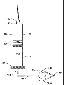
Hydraulic cylinder 100, as described in Figure 2, consists of two chambers,
110 and 120. Chamber 110 (corresponding to the pump chamber) is filled by
hydraulic working fluid 112 from a hydraulic reservoir 114. Filling is
accomplished
by means of a connective passage 116, such as (but not limited to) a tube or
lumen
either flexibly or rigidly connecting hydraulic reservoir 114 and hydraulic
cylinder
100. As hydraulic fluid 112 is forced out of reservoir 114 by actuator 135
(consisting, in an exemplary embodiment, of peristaltic compression plates
135A
-11-
CA 02523267 2005-10-21
WO 2004/094823
PCT/US2004/012797
and 135B and hinge 135C), chamber 110 fills with hydraulic fluid expanding its
volume and thus forcing piston element 130 (barrier mechanism) into chamber
120
(corresponding to the fluid chamber). The dotted lines in the actuator and the
piston
in Figure 2 represent the later-in-time position of a plate-hinge actuating
mechanism,
and the later-in-time position of the bather / piston.
Figure 3 is a schematic diagram illustrating one advantage of the fluid
delivery system, e.g., its ability to tolerate relatively large variations in
force
generating the over-pressure, to create a relatively constant fluid delivery
rate over
time or distance traveled by the barrier piston. It is apparent that without
the
hydraulic pump system, any direct use of force to expel fluid in the fluid
chamber
will be hard to control, and will be subjected to a large variation in
delivery rate of ,
the fluid (Figures 3A). In contrast, with the hydraulic pump, the delivery
rate is
much more constant (Figure 3B).
Chambers 110 and 120 can be, but are not necessarily separate, physical
25 In one embodiment, as shown in Figure 4A, the piston element 130 in
Figure
2 is replaced by a flexible membrane 132 separating the pump chamber 110 and
the
fluid chamber 120. The flexible membrane can expand in response to the
increased
pressure from the pump chamber 110, due to the increase in volume of the
working
fluid entering the pump chamber 110 through aperture 152. This in turn expels
fluid
-12-
CA 02523267 2005-10-21
WO 2004/094823
PCT/US2004/012797
In another embodiment, as shown in Figure 4B, chambers 110 and 120 may
each has a separate wall unit 134 and 136, respectively (such as expandable
bags
made from flexible materials). By virtue of being within the limited
confinement of
cylinder 100, the expansion in volume of chamber 110 necessarily leads to the
decrease in volume of chamber 120, creating a force to expel liquid from
chamber
120 via orifice 140.
In yet another embodiment, as shown in Figure 4C, the pump chamber 110
and the fluid chamber 120 may be separated from each other, but are
mechanically
coupled through a barrier mechanism 138 that transmits movements in pump
chamber 110 to that in the fluid chamber 120. The coupling mechanism 138 can
either augment or diminish the magnitude of the initial movement in the pump
chamber 110, such that the corresponding movement in the fluid chamber 120 is
increased, or decreased, respectively, resulting in expelling a larger or
smaller
amount of medicament fluid from the fluid chamber 120. For example, the
coupling
mechanism 138 can be two pistons linked by a shaft, as shown in Figure 4C. In
one
embodiment, the fluid chamber 120 may be detached from the pump chamber 110,
so that a new fluid chamber (120', not shown) may be re-attached.
As noted above, chamber 120 is to be initially filled with a quantity of
liquid
component to be delivered, such as a medicament. In the case of a medicament,
the
quantity would typically be determined by a medical professional in order to
provide
the necessary dosing over a pre-determined period of time. The volume of the
fluid
chamber may be about 100 pl, 500 p1, 1 ml, 3 ml, 5 ml, 10 ml, 30 ml, 50 ml,
100 ml
or more.
The depicted hydraulic cylinder 100 in Figure 2 can be further connected to
an infusion set 160 through orifice 140 at the distal end of chamber 120
(distal here
meaning the end of chamber 120 distant from piston 130). In other words, the
output
orifice 140 of hydraulic cylinder 100 is on the opposite end of the cylinder
from
hydraulic fluid input aperture 152, as one would commonly expect in a
hydraulic
system. However, this is merely one of the preferred designs. The output
orifice 140
-13-
CA 02523267 2009-06-05
52281-3
could be located on the wall of cylinder 100 at the chamber 120 portion if
desired
(see Figure 5 below).
Attached to orifice 140, in some embodiments, is an infusion device or "set"
160 selected from any of the infusion means conventionally known and used in
the
medical arts. Examples of infusion devices include: a needle, such as depicted
in
Figure 1; a lumen and needle set; a catheter-cannula set; or a microneedle or
microneedle array attached by means of one or more lumens. One of ordinary
skill in
the art will readily appreciate that many devices exist to convey medicaments
into a
body. Accordingly, the invention is not limited in the types of infusion or
injection
devices used therewith.
In an illustrative embodiment, as shown here in a high-level schematic
drawing in Figure 5, the fluid delivery system is affixed to a delivery area
of a
patient, e.g. skin 200, by an adhesive means, such as a transdermal patch. The
fluid
chamber 120 is connected to a microneedle or an array of microneedles 180,
such as
-15 those described in U.S. Pat No. 6,503,231.
Unlike what is shown in Figure 5, the microneedle(s) need not completely enter
the
skin layer 200. To achieve a low profile, both the pump chamber 110 and the
fluid
chamber 120 may be flat in shape (rather than shaped like a cylinder), and the
outer-
surfaces may hug the contour of the attached skin layer 200. The orifice(s)
(not
shown) connecting the fluid chamber and the microneedle(s) preferably opens on
a
side-wall of the fluid chamber 120. Alternatively, a connective passage may
link the
orifice on fluid chamber 120 to the microneedle or microneedle(s) array.
Barrier 130
and aperture 152 are as described above. Also shown is one embodiment of the
actuator, where plates 135 actuated by spring mechanism squeeze the hydraulic
fluid
reservoir 114 to inject hydraulic working fluid into the pump chamber 110.
Other
= actuators, such as those described in other parts of the specification,
may be adapted =
for use in this embodiment.
As exemplified in Figure 2, in operation, the fluid (e.g. medicament) is
administered by compressing hydraulic fluid reservoir 114 in a controlled
manner
with actuator 135. Figures 2 shows an exemplary peristaltic mechanism actuator
-14-
CA 02523267 2005-10-21
WO 2004/094823
PCT/US2004/012797
135. However, the actuator may be alternatively selected from any of a number
of
squeeze devices that apply a force on the reservoir, such as a miniaturized
bellows
crank or paired rollers bearing on reservoir 114 (see Figure 6 below).
Moreover, in
other embodiments, the reservoir can be acted on by an expanding gas volume,
thermal energy, or any other device or process that will be capable of causing
the
fluid to apply a pressure, either directly or indirectely, to the medicant
being
delivered.
In the embodiment shown in Figure 2, plates 135A and 135B are attached by
hinge 135C and forced together by means of a spring or, in some embodiments,
one
or more piezoelectric elements, such that flexible (e.g., elastomeric)
hydraulic fluid
reservoir 114 is squeezed between them. Squeezing an elastomeric reservoir
forces
the contents of the reservoir out through whatever aperture exists in the
reservoir. In
some embodiments, an aperture 152 is provided by the coupling tube 116 and the
adjustable aperture 150, further described below.
Actuator 135 may also take on others forms. Ratchet or stepper motor driven
units that compress plates or other structures bearing on hydraulic reservoir
114 that
move hydraulic fluid may also be used without departing from the present
invention.
Additionally, for a two-plate hinged peristaltic mechanism such as that
represented
by reference designator 135 in Figure 2, springs mounted internally or
externally to
the plates (not shown) may be used to force the plates together. Electrically
driven or
piezoelectric mechanisms, such as those described in the prior art, may also
be
employed.
In one embodiment, as shown in Figure 6A, one or more external spring(s)
135D having a constant spring coefficient over its full range of motion is
(are)
employed. (For the sake of simplicity, a single spring configuration is
described. But
multiple springs may be used to adjust forces.) This spring is disposed so as
to
connect portions of plates 135A and 135B distant from hinge 135C and to draw
them together (inwardly), thus bearing on reservoir 114. Thus, when the system
is
initially prepared for use, the spring is extended (i.e., placed in tension)
by forcing
plates 135A and 135B apart. The plates are then held in place with a removable
-15-
CA 02523267 2005-10-21
WO 2004/094823
PCT/US2004/012797
brace or other device (not shown) to keep them from compressing hydraulic
reservoir 114. Once the pump is in place and connected through infusion means
160
(see Figure 2, but not shown here) to inject the medicament into the patient,
the
brace may be removed. The constant spring tension placed on plates 135A and
135B
of actuator 135 will then slowly force the plates together and squeeze
hydraulic fluid
112 out of reservoir 114 in a peristalsis-like action.
In another embodiment, as illustrated in Figure 6B, a compressed spring or
set of springs 260 may be used to push a piston element 250 through a guided-
path
to compress the hydraulic fluid reservoir 114. At the end of the reservoir,
distal to
the piston element 250, is an aperture 152 that allows the hydraulic fluid 112
to enter
the adjacent pump chamber 110, so that barrier 130 may move accordingly. In a
more simplified version, the spring mechanism 250 and 260 may be replaced by
thumb force 300, just like in a traditional syringe (Figure 6C). In both
Figures 6B
and 6C, there is no connective passage separating the fluid reservoir 114 from
the
pump chamber 110.
The adjustable aperture provides regulation of the hydraulic pressure and
flow rate in the pump chamber 110. This regulation may be effected by allowing
the
aperture 152 (in Figure 2) to be adjusted to extremely small dimensions, for
example, to a diameter of one-ten thousandths of an inch (0.0001 inches, or
about
2.5 gm) or less.
In one embodiment, the aperture 152 has a fixed size. It does not have to be
round / circular in shape. For example, it could be roughly a square, a
triangle, an
oval, an irregular shape, or a polygon. Whatever the shape, the area of the
opening
will be sized to achieve the flow rate desired. In example, the opening may be
about
one-tenth thousandths of an inch (or 2-3 m) in diameter. Depending on use,
the
opening size can be anything, including an opening between 200 nm ¨ 500 nm, or
500 nm ¨ 1000 nm, or 1-2 pm, or 5-10 pm. Other sizes and dimensions can be
selected and the size and dimension selected will depend upon the application
at
hand.
-16-
CA 02523267 2005-10-21
WO 2004/094823
PCT/US2004/012797
In other embodiments, as shown in Figure 7, the aperture 152 may be
adjustable in size, as by means of a conventional iris mechanism (see Figure
7),
miniature valve, or paired gating slits (for example and not by way of
limitation)
currently known in the arts. For example, the adjustable aperture 152 may be
adjusted by means of a simple thumb wheel 150 that activates the conventional,
miniaturized valve or iris device discussed above. In an alternate embodiment,
an
electrical motor or piezoelectric device may be used to open or close the
aperture,
thus affecting the rate at which hydraulic fluid 112 flows into chamber 110
and
moves barrier 130.
Regardless of whether the aperture is adjustable or not, the flow rate of the
hydraulic fluid can be controlled to suit different needs. In certain
embodiments, the
quantity of the fluid in the fluid chamber is expelled at a rate selected
from: about
100 nl -1 jtl per minute, about 1-10 1 per minute, or about 10-100 IA per
minute. In
other embodiments, the fluid rate is mediated and controlled to be from
.0011_11 per
hour to 100 milliters per hour. The rate selected will depend upon the
application at
hand, and those of skill in the art will be able to determine the proper
dosage rate for
a given application.
One feature of aperture 152, whether adjustable or not, is that it can be made
extremely small so that hydraulic fluid 112 enters chamber 110 at very low
rates,
such as but not limited to rates as low as ones or tens of micro-liters per
minute.
When used with a hydraulic fluid of appropriate viscosity (further discussed
below),
the configuration of aperture 152 enables precise pressure regulation that is
insensitive to ambient pressure or other environmental conditions. This
insensitivity,
in turns, allows for highly accurate dosing and dose regulation under a wider
range
of conditions than previously seen in the arts.
Hydraulic fluid 112 is, in some embodiments, an ultrapure, high viscosity,
bio-inert material. Viscosity is limited at its upper bound by the amount of
force
developed by the actuator. In certain embodiments, the force generated by the
actuator is about 10 lb, 5 lb, 3 lb, 2 lb, 1 lb, 0.5 lb, 0.1 lb, .001 lb or
less. At its lower
bound, the fluid must be viscous enough so that the flow can remain highly
regulated
-17-
CA 02523267 2005-10-21
WO 2004/094823
PCT/US2004/012797
by the combination of actuator pressure and aperture diameter in all
environment
conditions, especially in the presence of low atmospheric pressure and/or high
ambient temperature (where viscosity tends to decrease). A simple test may be
performed to roughly determine the average flow rate of the hydraulic fluid,
by
fixing an aperture size and the pushing force exerted on the fluid reservoir,
and
determining the amount of hydraulic fluid remaining in the reservoir (and thus
the
amount exited) after a period of time. Consecutive periods of hydraulic fluid
loss
(e.g. fluid loss in consecutive 5-minute periods, etc.) may be measured to
determine
if the rate of hydraulic fluid loss from the reservoir is constant over time
under the
condition used.
Medicaments suitable for use with the system presently disclosed include:
insulin, opiates and/or other palliatives, hormones, psychotropic therapeutic
composition, or any other drug or chemical whose continuous low volume dosing
is
desirable or efficacious for use in treating patients. Note too that
"patients" can be
human or non-human animal; the use of continuous dosing pumps is not confined
solely to human medicine, but can equally applied to veterinarian medicines.
In an alternate embodiment of the system, two or more hydraulic reservoirs
and actuators are provided (Figure 8). In an illustrative embodiment shown in
Figure
8A, the first reservoir 400 and actuator 235 are the same as or similar to
items 114
and 135 in Figure 2. The second reservoir 500 and actuator 235, which may use
the
same peristaltic actuator 135 as shown in Figure 2 or any other conventional
alternative, such as those described above, are provided with a separate
control. In
other words, the second actuator may be controlled independently of the first.
Both
fluid reservoirs are connected to the pump chamber wall 150, through apertures
154
and 156, respectively. The connection may optionally go through connective
passages 116. Such a configuration is useful in situations where special,
discrete
doses of the medicament may be necessary. For example, an insulin-dependent
diabetic may often find it necessary to receive an additional booster dose or
bolus of
insulin immediately after meals, in addition to and along with continuously
supplied
-18-
CA 02523267 2005-10-21
WO 2004/094823
PCT/US2004/012797
insulin during the day. The second actuator control may thus be operated
independently of the first actuator control mechanism to deliver the bolus.
In an alternative embodiment, shown in Figure 8B, hydraulic fluid 112 from
both reservoirs 400 and 500 may pass together through a common lumen 116 and
thence through adjustable aperture 152 (Figure 8B). Alternatively, as
described
above, the two reservoirs may lead into hydraulic chamber 110 by way of
separate
lumens and separately adjustable apertures 154 and 156 (Figure 8A). In this
latter
configuration, the rate of dosing affected by either reservoir may be
independently
controlled through their respective adjustable apertures.
In a further alternative, one of the reservoirs may lead to a fixed aperture
while the other leads to an adjustable aperture. In this embodiment, useful in
cases
such as the insulin-dependent diabetic described above, the fixed-aperture-
connected
hydraulic reservoir can be actuated to provide bolus dosing at discrete
intervals,
while the adjustable-aperture-connected hydraulic reservoir can be used to
provide
continuous slow dosing.
EXEMPLARY EMBODIMENT USING THE FLUID DELIVERY SYSTEM
In one exemplary embodiment, there is provided a method of administering a
medicament, comprising: compressing a hydraulic fluid reservoir to force said
hydraulic fluid through a connection means; passing said hydraulic fluid
through an
adjustable aperture into a first, pump chamber, wherein said pump chamber is
separated from an adjacent fluid storage chamber, for example, by a moveable
barrier, and wherein said fluid storage chamber is filled with a medicament;
displacing said moveable barrier into said fluid storage chamber by filling
said pump
chamber with said hydraulic fluid, wherein said displacing causes a quantity
of said
medicament to be expelled from said fluid storage chamber through an orifice.
Said passing may be regulated by said adjustable aperture varying the flow of
said hydraulic fluid and thus the quantity of said medicament expelled through
said
orifice. Furthermore, the method may further comprise injecting a quantity of
said
medicament into a patient through an infusion set connected to said orifice.
-19-
CA 02523267 2005-10-21
WO 2004/094823
PCT/US2004/012797
In some embodiments, the step of compressing may employ peristaltic
compaction of said reservoir at a constant rate. Alternatively, the
compressing step
may employ peristaltic compaction of said reservoir at a variable rate.
In yet another alternate embodiment, the method may further comprise
rapidly compressing a second hydraulic reservoir fluidly connected to said
pump
chamber to displace said moveable barrier and thus cause a bolus of said
medicament to be expelled through said orifice. This embodiment may further
comprise passing said hydraulic fluid from said second hydraulic reservoir
through a
second aperture into said pump chamber.
Alternate Embodiments
The order in which the steps of the present method are performed is purely
illustrative in nature, and may not need to be performed in the exact sequence
they
are described. In fact, the steps can be performed in any suitable order or in
parallel,
unless otherwise indicated as inappropriate by the present disclosure.
While several illustrative embodiments of the hydraulic pump system and its
use in the fluid delivery system have been shown and described, it will be
apparent
to those skilled in the art that changes and modifications may be made without
departing from this invention in its broader aspect and, therefore, the
appended
claims are to encompass within their scope all such changes and modifications
as
fall within the true spirit of this invention.
-20-