Note: Descriptions are shown in the official language in which they were submitted.
CA 02525803 2005-11-14
WO 2004/110526 PCT/EP2004/006482
Modular infusion pump
The invention relates to a modular infusion pump for
administering a product, preferably insulin or another
medicament.
Particularly in self-administration of medicaments, for
example insulin, the persons using the medicament in
question, and administering it themselves by means of
an infusion pump, are increasingly placing importance
on convenience and discretion. Manufacturers are
meeting these demands by, among other things, dividing
the infusion pump into structural assemblies which are
each arranged in their own housing and can be joined to
one another by wireless or wired connection.
Modular infusion pumps of this kind are known, for
example, from DE 30 35 670 A1 and DE 198 40 965 A1.
According to these, an infusion pump is split up into a
pump head, which is implanted directly on the body or
even within the body and comprises a product-containing
reservoir and a delivery device, and an operating and
control part which can be carried at a distance from
the pump head, for example on or in clothing. The
operating and control part and the pump head are in
wireless communication with one another.
It is an object of the invention to further improve the
convenience of modular infusion pumps of this kind.
Accordingly, the invention relates to a modular
infusion pump for administering a product, comprising a
pump housing, a reservoir for the product, a delivery
device, and an energy source. The pump housing is
preferably designed in such a way that it can be placed
with an underside directly onto human or animal skin.
The reservoir can be formed directly by the pump
housing. However, the reservoir is preferably in the
CA 02525803 2005-11-14
- 2 -
form of a receptacle, in particular an ampule, which is
received by the pump housing and is preferably
exchangeable. The pump housing also stores the delivery
device, which preferably comprises a motor for
generating a delivery movement. The pump housing forms,
together with the infusion pump components received by
it, a first module, namely a pump head. The components
received by the pump housing are preferably
accommodated in the pump housing. However, within the
meaning of the invention, received is also understood
to refer to those components which are secured on the
outside of the pump housing or are at least not
completely enclosed by the pump housing. Nevertheless,
complete enclosure and, in this sense, accommodation
within the pump housing are the preferred way of
arranging and storing the components of the pump head,
provided such components do not have to be removed from
the pump housing.
For the modular arrangement, the infusion pump
comprises a further housing which, in particular, can
receive a control device for the delivery device,
preferably for a motor of the delivery device, and/or
an operating device and/or a display device of the
infusion pump, as is known in principle from the prior
art.
According to the invention, however, the further
housing in this case receives the energy source for the
delivery device. The energy required for operating the
delivery device is preferably transmitted by wire
between the further housing and the pump housing.
Instead of this, however, wireless transmission would
also be possible, especially over short distances of
approximately 50 cm or less.
Compared to conventional infusion pumps which combine
all the pump components in a single housing, the
modular infusion pump according to the invention
CA 02525803 2005-11-14
- 3 -
affords the advantage that the reservoir and the
delivery device are at all times arranged in immediate
proximity to the site of administration, generally a
puncture site, and can remain there at least until the
reservoir is exchanged or topped up. Compared to the
known modular infusion pumps which in principle also
afford this advantage, the weight and size of the pump
head can be reduced still further. The reduction in the
weight and volume of the energy source is not the only
advantage here. By removing the energy source from the
pump head, the pump housing can be simplified and the
weight and volume of the pump housing itself can also
be reduced.
In preferred embodiments, parts of the control device
of the infusion pump, or preferably the whole control
device, can be relocated from the pump head. The
control device or the relocated parts can in particular
be received by the further housing. The control device
is divided into a power section, via which the energy
source supplies the delivery device with energy, and a
signal-processing part which controls the power section
and, via the power section, also the delivery device.
The control device is preferably developed as a
controlling and regulating device, but for the sake of
simplicity it will always be referred to below simply
as a control device. Of the control device, at least
either the power section or the signal-processing part,
or preferably both the power section and the signal-
processing part, are relocated from the pump housing,
i.e. from the pump head.
Of the energy supply system for the delivery device,
preferably only the line or the several lines for
energy transmission are arranged in the pump housing.
The delivery device is preferably also controlled and
advantageously regulated via this line or these several
lines.
CA 02525803 2005-11-14
- 4 -
If, as is preferred, the control device also regulates
the delivery device and accordingly comprises a
position and/or speed sensor which detects a position
and/or speed of a component of the delivery device,
preferably of said motor, the pump housing then
receives, in addition to the sensor, preferably only
the lines necessary for the energy supply and/or signal
transmission of the sensor, if appropriate only a
single line for the combined transmission of energy and
signals.
If, as in preferred embodiments, an occlusion and/or
leak detector is to be arranged in the pump housing,
then the comments made above concerning the position or
speed sensor also apply to the energy supply and signal
transmission of this detector.
In a particularly preferred embodiment, the pump
housing thus serves as a support only for the
reservoir, for components located downstream of the
reservoir in a product-carrying system comprising the
reservoir, for a drive mechanism generating the
delivery movement of the delivery device, and for the
other components of the delivery device driven by the
drive mechanism. If appropriate, the pump housing is
also the support for one or more sensors for
controlling the drive mechanism, if the latter is
regulated, and for additional monitoring devices, for
example an occlusion and/or leak monitor device.
The drive mechanism can in particular be a motor,
preferably an electric rotary motor. However, an
electric linear motor can in principle also be used. It
is in principle also quite conceivable for the motor to
be a pneumatic or hydraulic motor. The driving of the
delivery device can alternatively also be based on
other effects, for example a piezo effect. Microsystem
pumps are also conceivable. Conventional drives are
preferred, however.
CA 02525803 2005-11-14
- 5 -
The energy source is preferably an electric battery or
an electric accumulator. Here too, however,
alternatives are conceivable, for example the energy
source being in the form of a pressure reservoir, a
fuel cell, or an additional supply pump for supplying a
pneumatic or hydraulic motor with the working fluid.
According to another aspect of the invention, an
infusion cannula protrudes beyond the underside of the
pump housing only by a cannula length that is to be
introduced into or beneath the skin. This feature is
also considered satisfied when, for example, the
infusion cannula is guided laterally out of the pump
housing and is guided along a side wall of the pump
housing to the area of the underside and is then
continued past the underside by said cannula length. It
is particularly preferable, however, that the infusion
cannula protrudes from the housing only by said cannula
length. A connecting line, which connects the reservoir
to the infusion cannula, is preferably 5 cm long and,
still more preferably, shorter than 5 cm. The Applicant
reserves the right to claim separate protection for the
aspect as described in particular in claim 18, i.e.
even without relocation of the energy source from the
pump housing, which for separate protection is only a
preferred embodiment.
Since the infusion cannula to be introduced into body
tissue is provided directly at or preferably even on
the pump housing, this ensures that the reservoir and
an infusion cannula outlet located in the body tissue
have the same hydrostatic height or, at any rate, a
difference in height that is negligible for practical
purposes. Therefore, a siphoning effect, i.e. a suction
situation in the reservoir, resulting in uncontrolled
dispensing of product, cannot arise. A particular
advantage is also that product losses associated with a
priming of the infusion pump are minimized. Priming is
the term used to describe the procedure by which air is
CA 02525803 2005-11-14
- 6 -
removed from the product system extending from the
reservoir to the outlet of the infusion cannula. The
shortening of the product system also contributes to
reducing the risk of occlusions and/or leaks in the
system. Finally, by omitting a catheter which is guided
out from the housing and which in conventional infusion
pumps extends as far as the infusion cannula, the
number of disposable articles to be kept in stock by
the user and to be carried around when traveling can
also be reduced.
The reservoir can form a product outlet on the
underside of the pump housing, such that the infusion
cannula can be directly joined to the reservoir outlet.
In the case of the preferred delivery of the product by
means of a piston which is received in the reservoir
and can be moved toward a reservoir outlet, the
reservoir outlet will in most cases point in the
direction of movement of the piston, and therefore in
most cases at an angle, in general at a right angle, to
the underside of the pump housing. In a preferred
embodiment of this kind, the connecting line also
bridges the angle between the reservoir outlet and the
infusion cannula.
In a preferred embodiment, the pump housing is in
several parts, particularly preferably in two parts,
and comprises a main housing, which receives or itself
forms the reservoir, and a secondary housing from which
the infusion cannula protrudes and which is secured on
the main housing. The secondary housing is
advantageously secured releasably onto the main housing
by hand and without aids. After it has been undone, the
connection can particularly preferably be re-
established by one or more simple maneuvers. The main
housing and the secondary housing are connected to one
another preferably by means of a coupling, for example
in the form of a screw connection or preferably a
bayonet connection or a simple plug-in connection or a
CA 02525803 2005-11-14
_ 7 _
catch connection or a combined plug-in and catch
connection. The main housing and the secondary housing
can additionally be locked together when the coupling
is designed as a screw or bayonet connection.
The secondary housing preferably forms an angle adapter
which bridges an angle between the reservoir outlet and
the infusion cannula.
The secondary housing can be connected to the main
housing so as to be movable in rotation about at least
one axis of rotation, in order to decouple the infusion
cannula from rotation movements of the main housing
about the axis of rotation. The securing to the main
housing can also be so configured that the main housing
can execute rotation movements about two or even three
axes of rotation relative to the secondary housing, so
that still more extensive decoupling is achieved. It is
also conceivable that the secondary housing is guided
such that it can move in translation on the main
housing by a short distance. However, in a preferred
and particularly simple embodiment, the secondary
housing is secured rigidly on the main housing,
preferably by means of the releasable coupling.
Further preferred features of the invention are
described in the dependent claims and through the
combinations of the claims.
An illustrative embodiment of the invention is
explained below with reference to figures. Features
which become apparent from the illustrative embodiment
advantageously represent, either singly or in each
combination of features, a development of the subjects
of the claims and of the configurations described
above. In the drawing:
Figure 1 shows a modular infusion pump according to
the invention,
CA 02525803 2005-11-14
-
Figure 2 shows a pump head of the infusion pump in a
side view,
Figure 3 shows the pump head in a front view, and
Figure 4 shows the pump head in a plan view.
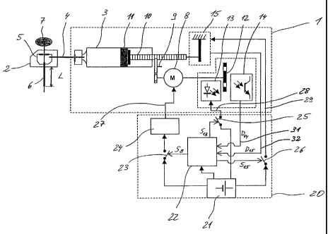
Figure 1 shows an infusion pump made up of two modules.
A first of the two modules is arranged directly on the
skin at an infusion site and is referred to below as
the pump head. The pump head is accommodated in a two-
part pump housing which lies with an underside on the
skin and, for such an arrangement, is equipped with
corresponding securing means, for example an adhesive
pad or a strap. The pump housing consists of a main
housing 1 and a secondary housing 2 which are connected
to one another mechanically by means of a coupling
mechanism so that they can be easily and quickly
released from one another by hand and without aids and
can then be connected to one another again.
The main housing 1 accommodates a reservoir 3, which is
filled with a liquid product, a delivery device 8-11
for delivering the product, a position sensor 12-14
assigned to the delivery device 8-il, and also an
occlusion and leak detector 15. The liquid product can
be a liquid medicament in particular, for example
insulin. The delivery device 8-11 is formed
conventionally as a piston pump with spindle drive. The
force required for delivering the product is generated
by means of an electric motor 8 whose drive speed,
translated by a toothed gear wheel 9, is transmitted to
a piston rod 10 guided rectilinearly in the axial
direction in the main housing 1. The piston rod 10 is
formed as a threaded rod. An output gear wheel of the
gear 9 is in threaded engagement with the thread of the
piston rod 10. Because it is guided rectilinearly, the
piston rod 10 is thus moved axially in an advancing
direction when the output gear wheel of the gear 9 is
CA 02525803 2005-11-14
_ g _
driven in rotation. The piston rod 10 then presses
against a piston 11 which is received in the reservoir
3 and which is thus moved in the reservoir 3 in the
direction toward an outlet of the reservoir 3, the
direction of mobility of the piston 11 being identical
to the advancing direction of the piston rod 10. An
advance movement of the piston rod 10 causes a similar
advance movement of the piston 11 and, consequently,
the displacement of product through the outlet of the
reservoir 3. The delivery device 8-il thus accommodates
the motor 8 and all the components arranged downstream
in the force flow starting from the motor 8, including
the delivery member acting directly on the product,
namely the piston 11.
The product is administered through a flexible infusion
cannula 6. The infusion cannula 6 protrudes from the
underside of the secondary housing 2; in the
illustrative embodiment it protrudes through a housing
wall forming the underside of the secondary housing 2.
For subcutaneous administration, the infusion cannula 6
is introduced into the body tissue by its entire
cannula length L protruding beyond the underside of the
secondary housing 2. The cannula length L is the length
of the infusion cannula 6 measured between the
underside of the secondary housing 2 and the front free
end of the infusion cannula 6.
Besides the product-carrying parts extending from the
reservoir 3 to the infusion cannula 6, the motor 8, the
components of the delivery device 8-11 arranged
downstream of the motor 8, and the two sensors 12-14
and 15, the pump head only comprises lines for supply
of energy to these components and for signal
transmission to and from these components. All other
components of the infusion pump are integrated in a
further module with a separate, further housing 20. The
further module is a service module in which, in
particular, the energy supply for all the components of
CA 02525803 2005-11-14
- 10 -
the pump head is integrated. It also integrates all the
functions for control and regulation of the components
of the pump head. Where, because of the feedback of one
or more variables, the system is not only controlled
but also regulated, the following will deal, for the
sake of simplicity, only with the control and,
accordingly, with a control device or, in brief, a
control. In addition to the two functions of energy
supply and control, the service module also integrates
all of the operating functions and also all of the
optical and/or acoustic display functions. The pump
head therefore only contains those components of the
infusion pump which are needed for delivering the
product and for monitoring correct delivery, and it
therefore has a particularly low weight and a
particularly small volume. By virtue of these two
properties, the pump head is particularly suited for
arrangement directly at the infusion site. Because of
the arrangement directly on the body, however, the pump
housing 1/2 can advantageously receive a vibration
alarm.
The housing 20 of the service module accommodates, in
particular, an energy source 21 which supplies the
required energy to all the components of the infusion
pump. In the illustrative embodiment, the energy source
21 is a battery or an electric accumulator. A control
device is also shown, with its main inputs and outputs.
The control device comprises a signal-processing part
22 and, especially for the motor 8, a power section 24,
in the illustrative embodiment power electronics. It
also comprises several interrupters, namely an
interrupter 23 in the energy supply line for the motor
8, an interrupter 25 in the energy supply line for the
position sensor 12-14, and an interrupter 26 in the
energy supply line for the occlusion and leak detector
15. All three energy supply lines issue from the common
energy source 21. Of course, the energy source 21 can
also be formed by a number of separate energy sources
CA 02525803 2005-11-14
- 11 -
in combination. However, the energy source 21 is
preferably constituted in its entirety by a single
battery or a single accumulator. The signal-processing
part 22 controls each of the interrupters 23, 25 and 26
by means of the latter's own actuating signal, namely
by means of an actuating signal S$ for the interrupter
23, an actuating signal S13 for the interrupter 25, and
an actuating signal Sls for the interrupter 26. The
output signals of the two sensors or detectors 12-14
and 15 are fed to the input of the signal-processing
part 22. The output signal of the position sensor 12-14
is designated by D14, and the output signal of the
occlusion and leak detector 15 is designated by Dls.
The output signal D14 represents the rotation angle
position of the motor 8. For detection of the rotation
angle position, the position sensor 12-14 comprises a
perforated disk which is mounted, fixed in terms of
rotation, on a shaft of the motor 8. A light-emitting
diode 13 is arranged to one axial side of the
perforated disk 12, and a phototransistor 14 to the
other side, both of these secured to the housing. The
phototransistor 14 receives the light emanating from
the light-emitting diode 13, and passing through the
perforated disk 12, and emits it as output signal D14 to
the input of the signal-processing part 22 via a signal
line 31. The output signal D14 of the position sensor
12-14 forms the controlled variable for controlling the
motor 8. The signal-processing part 22 generates the
reference variable in accordance with a predetermined
program, compares this with the controlled variable D14
and, as a function of this comparison, forms the
actuating signal S8 for the interrupter 23. Depending
on the actuating signal S8, the interrupter 23 adopts
one of two possible switch positions. In one switch
position, it closes the line for energy supply to the
motor 8, and, in the other case, it interrupts this
line. The motor control can be of a conventional nature
and therefore does not require any further explanation
CA 02525803 2005-11-14
- 12 -
here, other than to point out that all its components,
except for the line 27 for energy supply to the motor
8, are components of the service module and not of the
pump head. Because of the slip-free transmission of
force from the motor 8 to the piston rod 10, the
rotation angle position of the motor 8 at the same time
also represents the position of the piston rod 10 and,
consequently, of the piston 11 in the reservoir 3. From
the rotation angle position of the motor 8, it is
therefore possible to draw conclusions directly
concerning the amount of product delivered and the
residual amount remaining in the reservoir 3. The
position sensor 12-14 can also be used, in principle,
to determine the number of revolutions and thus the
speed of rotation of the motor 8 and, consequently, the
advancing speed of the piston 11 and thus the delivery
speed or delivery rate. This is not absolutely
essential, however.
The interrupter 25, arranged for energy-saving reasons
in the energy supply line for the light-emitting diode
13, is likewise a simple switch with two positions
which closes the energy supply line in one of the two
positions and interrupts it in the other position. The
interrupter 25 is also a component of the service
module and is arranged in the housing 20 of the latter.
Only the remaining part 28 of the energy supply line
for the light-emitting diode 13 and the remaining part
of the signal line 31 are accommodated in the main
housing 1 of the pump head.
The occlusion and leak detector is used to measure the
reaction force acting on the piston rod 10 during
delivery, and the output signal D15 represents the
measured reaction force. The occlusion and leak
detector 15 serves exclusively for monitoring purposes.
If, on the basis of the output signal D15, the signal-
processing part 22 determines the occurrence of an
occlusion or a leak in the product-carrying part of the
CA 02525803 2005-11-14
- 13 -
infusion pump, the signal-processing part 22 interrupts
the energy supply to the motor 8 by means of a
corresponding actuating signal SS and thus stops the
delivery device 8-il.
The position sensor 12-14 can of course also serve as a
further monitoring device. For example, as a function
of its output signal D14, a vibratory alarm signal could
be emitted by means of a vibration alarm.
In the illustrative embodiment, the occlusion and leak
detector 15 is also supplied with energy, namely via
its own energy supply line 29 from the energy source
21. The interrupter 26, also formed as a single switch
with two possible positions, is arranged in the energy
supply line. As regards the energy supply for the
detector 15 and the latter's output signal, once again
only the remaining parts of the lines 29 and 32 are
arranged in the pump housing 1/2, so as to minimize the
volume and weight of the pump head.
The two interrupters 25 and 26 serve to save energy and
assume their respective closed position during running
of the motor. They are preferably brought directly into
the closed position when the control 22-26 is switched
on, and they are brought immediately from the closed
position to the interrupt position each time this is
switched off . If the occlusion and leak detector 15 is
configured as a force sensor, it can be formed, for
example, as a strain gauge or instead, for example, as
a piezoelectric transducer and thus work without energy
supply. If the occlusion and leak detector works
without external energy, it is thus advantageously
possible to dispense with the energy supply line 29
provided for it and with the interrupter 26 and the
signal line or signal emitter for the actuating signal
Sis .
If the pump head has a vibration alarm, as is
CA 02525803 2005-11-14
- 14 -
preferred, such a vibration alarm would, for example
like the position sensor 12-14, be supplied with
electrical energy from the energy source 21. A further
interrupter in the nature of the interrupters 23 to 26
would be arranged in the supply line and would be
controlled from the signal-processing part 22 by a
corresponding actuating signal in such a way that the
energy supply line to the vibration alarm would be
closed and the vibratory alarm signal triggered.
Because the pump head is applied directly on the skin,
a vibratory alarm is particularly effective.
Another particularly advantageous feature of the pump
head is the short length of the product line to the
infusion cannula 6, this length being measured between
the outlet of the reservoir 3 and the upstream end of a
cannula length L. The cannula length L is the length by
which the infusion cannula 6 protrudes into the body
tissue during administration of the medicament. When
the cannula length L is introduced into the body
tissue, the product line length is the length measured
between the outlet of the reservoir 3 and the surface
of the skin. This length is not more than 5 cm,
preferably not more than 2 cm, and it can even be
smaller still.
The product line is formed by a connecting cannula 4, a
cavity enclosed by a diaphragm 5, and an upstream
endpiece of the infusion cannula 6 with which the
infusion cannula 6 protrudes into the secondary housing
2. The connecting cannula 4 penetrates a septum which
closes the outlet of the reservoir 3. At its opposite
downstream end, the connecting cannula 4 penetrates a
side wall of the diaphragm 5 and protrudes there into
the cavity of the diaphragm 5. Downstream from the
connecting cannula 4, the infusion cannula 6 likewise
protrudes with its upstream end into the cavity, so
that a liquid-tight product line is created from the
outlet of the reservoir 3 into the infusion cannula 6.
CA 02525803 2005-11-14
- 15 -
Since the infusion cannula 6 in the illustrative
embodiment is flexible and, in particular, not
resistant to bending, it is introduced with the aid of
a puncture needle 7 into the body tissue, i.e. into the
skin or preferably through the skin. The puncture
needle 7 has a sufficient stiffness to allow
puncturing. The infusion cannula 6 bears tightly around
the puncture needle 7 so that, as the puncture needle 7
punctures the skin, it is introduced along with the
puncture needle 7 into the body tissue. After the
infusion cannula 6 has been introduced, the puncture
needle 7 is withdrawn from the body tissue and from the
infusion cannula 6 and from the diaphragm 5. After
withdrawal of the puncture needle 7, the diaphragm 5
still seals the hollow cavity joining the connecting
cannula 4 and the infusion cannula 6.
For introducing the infusion cannula 6 into the body
tissue, it is advantageous if, as in the illustrative
embodiment, the secondary housing 2 is connected to the
main housing 1 of the pump head in such a way that,
when it is placed on the skin, the infusion cannula 6
is also simultaneously introduced into the skin or
through the skin and into the body tissue, and no
additional maneuver is needed for this other than that
of placement of the pump housing 1/2. In a preferred
and simple configuration, the secondary housing 2, as
in the illustrative embodiment, is connected to the
main housing 1 in a completely rigid, i.e. immovable,
manner, for example by means of a bayonet catch or
another suitable catch acting as a coupling. The main
housing 1 and the secondary housing 2 preferably form a
common smooth underside for placement on the skin. The
secondary housing 2 moreover forms an adapter which
bridges the angle between the outlet of the reservoir 3
and the surface of the skin.
Figures 2, 3 and 4 show the pump head in different
views of the pump housing 1/2. The infusion cannula 6
CA 02525803 2005-11-14
- 16 -
has been introduced by its cannula length L into the
body tissue. For placing the pump housing 1/2 on the
skin, Figure 2 shows a slit formed close to the
underside of the pump housing 1/2 for a securing means
17, for example an adhesive pad or a fastening strap.
Figure 3 shows, in a front view of the side face of the
secondary housing 2, an adhesive pad which is pulled
through the slit 16 and which protrudes from the main
housing 1 through both sides of the slit 16 and can be
affixed with its two free ends on the surface of the
skin. The infusion cannula 6 is perpendicular with
respect to the underside (plane in the illustrative
embodiment) of the pump housing 1/2 sitting on the skin
at the infusion site.
Figures 2 and 4 also show a plug-in connector 18 which
is inserted into a socket of the main housing 1. All
the energy and all the signals are transmitted to and
from the pump head via the plug-in connector 18 and via
the connecting cable 19 issuing from it. In the
illustrative embodiment, the transmission takes place
exclusively between the pump head and the service
module. The plug-in connector 18 is designed as an
angled plug-in connector. The connecting cable 19
leaves the plug-in connector 18 at a right angle to the
attachment to the pump head. Although a straight axial
attachment is also possible in principle, the design as
an angled plug-in connector is preferred because, in
this way, the transverse forces acting on the infusion
cannula 6 during movements of the body can be reduced.
The plug-in connector 18 is water-tight. The connecting
cable 19 is a highly flexible and shielded electrical
line. The connecting line 19 is either an integral
component of the control 22-26 or is coupled to this
control 22-26 likewise via a plug-in connector and a
corresponding attachment on the housing 20.
The integrity and correct function of the infusion pump
can be monitored, on the basis of the energy supply and
CA 02525803 2005-11-14
- 17 -
signal connection, more easily than in conventional
infusion pumps where a long connecting catheter extends
from the infusion pump all the way to the infusion
site, this monitoring being possible in the simplest
case by measuring the impedance, this impedance
measurement being carried out permanently or preferably
at regular intervals. By monitoring the energy supply
and signal connections, it is possible to detect and to
differentiate between relevant error situations, for
example an interruption or a short circuit, caused for
example by penetration of moisture. Compared to known
pump heads which are also placed directly in the skin,
an important advantage here is at least the shortened
product line between the outlet of the reservoir 3 and
the cannula length L by which the infusion cannula 6 is
introduced into the body tissue.
Another inherent advantage of the pump head that may be
mentioned is the possibility that, on the one hand, a
flow sensor can be arranged in immediate proximity to
the cannula length L introduced into the body tissue
and that, on the other hand, the connection needed for
signalling and, if necessary, for the energy supply of
the flow sensor can be made not via flexible line
catheters, but instead via the pump housing 1/2 which,
although of more than one part, constitutes a uniform
pump housing in the assembled state. This is not only
advantageous in the case of a wired connection, but
also in the case of a wireless connection of the flow
sensor. The connection and integration of a flow sensor
into the control system 22-26 would, for example, be
like the connection and integration of the occlusion
and leak detector 15.
The secondary housing 2, with all the pump head
components received by it, is designed as a disposable
article. This disposable article can, for example, be
exchanged each time the reservoir is topped up or
preferably completely replaced. The life time of the
CA 02525803 2005-11-14
- 18 -
disposable article can, however, also be longer. The
disposable article includes the components accommodated
in the secondary housing 2 and of course also the
infusion cannula 6 and preferably also the connecting
cannula 4. When the secondary housing 2 is secured on
the main housing 1, the connection to the reservoir 3
is also established at the same time.