Note: Descriptions are shown in the official language in which they were submitted.
CA 02526157 1999-05-21
MEDICAL RETRIEVAL BASKET
TECHNICAL FIELD
The present invention deals with a retrieval device for removing material from
a body.
BACKGROUND INFORMATION
Biological material, such as stones, can reside at least in the kidney,
ureter, or biliary
duct. Stones can be extremely painful and require medical treatment. Removal
of stones
from the body has been accomplished by two methods in the past. The first
method is stone
removal through conventional surgery; a treatment with obvious disadvantages,
risks and
drawbacks. The second method is to remove stones under the guidance of an
endoscope. In
this method a grasping device is guided through the body tract to the site of
the stone and is
used to grasp and remove the stone under endoscopic guidance. Grasping devices
which have
been used in the past for the removal of stones include basket devices that
have generally
straight legs that bow outward from the center of the basket.
SUMMARY OF THE INVENTION
The invention provides a device and method for retrieval of material from a
body.
More particularly, the invention relates to a device and method for
immobilizing a stone in the
body with a basket of the device so the stone can be effectively fragmented
and then allowing
the stone and/or the pieces thereof to be removed via the basket which is
formed, pursuant to
the invention, of multiple, spiral-shaped, generally parallel, non-
overlapping, and non-
intersecting legs that are flexible and relatively closely spaced to each
other (e. g., no more
than about 2mm apart).
The retrieval device of the invention includes the basket, a sheath movable
relative to
the basket, and a handle. The basket has spiral-shaped Legs disposed around a
central axis.
The spiral-shaped legs have improved flexibility and moveability. In an
intermediate section
of the basket, the spiral-shaped legs are disposed substantially parallel to
one another around
the central axis. The legs do not intersect. Intersecting legs tend to
restrain basket leg
flexibility.
CA 02526157 1999-05-21
2
In one aspect, the invention relates to a medical device for retrieving
material from a
body, comprising: a proximal handle; a sheath extending from the handle to a
distal end of the
sheath, the sheath including a lumen extending therethrough; and a basket
comprising at least
three legs, a collapsed position in which the basket is collapsed within the
lumen of the
S sheath, and another position in which the basket is located beyond the
distal end of the sheath
and expanded, the basket comprising a first portion, a second portion, and an
intermediate
portion extending between the first and second portions, wherein when the
basket is in the
other position, said at least three legs are non-intersecting, and said at
least three legs in the
intermediate portion are spirally arranged, substantially parallel, and said
intem~ediate portion
comprises a uniform diameter throughout its length. When in the expanded
position, the
basket can provide a support surface for the material when it is being
fragme~ited, and it can
further be used to captwe the fragmented material.
Embodiments of this aspect of the invemion can include the following features.
For
example, in one embodiment, the legs of the intermediate portion of the basket
may be spaced
about 0.0787 inches to 0.394 inches apart. In another embodiment, an elongate
member may
extend within the lumen of the sheath and may be operably attached to the
basket such that
movement of the elongate member relative to the sheath results in the basket
moving between
the expanded and retracted positions.
In another aspect, the invention provides use of the device in accordance with
different
embodiments of the invention for retrieving material in a body wherein the
basket is
positioned beyond the distal end of the sheath.
In another aspect, the invention provides a device for retrieving and/or
immobilizing
material in a body, comprising: a sheath including a lumen extending
therethrough, a sheath
wall and a distal end; and a basket extending from the sheath wall at the
distal end of the
sheath, said basket comprising a first basket portion and a second basket
portion with at least
two legs extending from the first basket portion to the second basket portion,
the basket
further comprising an intermediate portion between the first and second
portions in which the
legs of the intermediate portion are spirally arranged, substantially
parallel, and non-
intersecting, said basket moveable between a retracted and an expanded
position; and, an
elongated member axially disposed in the lumen of the sheath and operably
attached to said
second basket portion such that axial movements of said elongated member
results in said
basket transitioning between the retracted position and the expanded position
in which said
CA 02526157 1999-05-21
intermediate portion is radially displaced outward relative to said first and
second basket
portions. The invention also relates to use of this devise for retrieving
material in a body
wherein the basket is in the expanded position.
In another aspect, the invention provides a catheter for retrieving an object
in a body
S tract, comprising: a sheath having a wall, the sheath defining a lumen
therethrough and having
a first end and a second end; a mesh embedded in the wall of the sheath, the
mesh having a
first mesh portion moveable between a retracted position and an expanded
position; and, an
elongated member disposed in the:lumen and operably attached to one of the
first mesh
portion and the sheath such that axial movement of the elongated member within
the lumen
causes movement of the first mesh portion between the expanded position and
the retracted
position.
In another aspect, the invention provides a guidewire for immobilizing
material in a
body tract, comprising: an outer sheath; an inner core moveable within the
outer sheath; and,
an expandable element disposed in a distal region of the guidewire, the
expandable element
being moveable between a retracted position and a radially expanded position
based on axial
movement of the inner core relative to the outer sheath, the expandable
element, when in the
expanded position, forming an object supporting surface for supporting an
object in a body.
In another aspect, the invention features a method for fragmenting and
retrieving
material (e. g., a stone) from a body tract. This method involves inserting
into a body tract a
device such as the device described above. The method further includes
immobilizing
material in the body tract by moving the basket from the retracted position to
the expanded
position whereby the material is blocked, and then fragmenting the material in
the body tract
while using the expanded basket to limit movement of the material during
fragmentation. The
expanded basket can then be manipulated to capture at least some of the
fragmented material
within the basket. The captured fragmented material is then recovered from the
body by
withdrawing the device from the body tract.
CA 02526157 1999-05-21
4
BRIEF DESCRIPTION OF THE DRAWINGS
F1G.1 is a side view of an expandable devicx according to the present
invention.
FIG. 2 is a side view of the expandable device of FIG.1 deployed in a duct or
tract or
vessel of a body.
FIGS. 3 and 4 illustrate different configuratiops obtainable using the
expandable device
according to the present invention.
FIG. SA shows an end view of the expandable device according to the present
invention.
FIGS. SB and SC illustrate another embodiment of the present invention:
FIGS. SD-SH illustrate other embodiments of the present invention:
FIG. 6 illustrates one embodiment of the present invention wherein the
expandable
element is formed by embedding material in a sheath.
FIG. 7 illustrates another embodiment of an expandable device according to the
present
invention.
FIGS. 8A, 8B, 8C and 8D illustrate another embodiment of an expandable device
15 according to the present invention in which the expanded diameter of the
eicpandable element is
variable.
FIG. 9A illustrates another embodiment of the present invention in which the
expandable -
element is formed in a guide wire with detachable proximal handles.
FIGS. 9B and 9C illustrate another embodiment of the present invention.in the
form of a
20 guidewire.
FIGS. 1 OA and l OB illustrate another embodiment which is similar to that
ofFIGS. SB
and SC.
FIG. 1 OC is an end-view of the basket in FIG. 1 OB.
FIGS. 11A and I 1B illustrate another embodimem which is a variation of the
25 embodiment shown in FIGS. 8A-8D.
FIGS. I 2A-E illustrate the clinical application of the embodiment of the
invention
illustrated in FIGS. 11 A and 11 B.
FIGS. 13A-B illustrate another embodiment of the invention including the
basket with
spiral-shaped legs.
30 FIGS. 14A-E illustrate a clinical application of the embodiment of the
invention
illustrated in FIGS. 13A and 13B.
CA 02526157 1999-05-21
DESCRIPTION
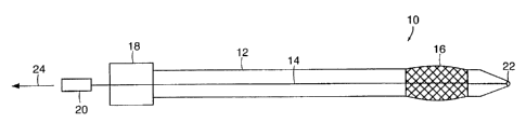
FIG.1 illustrates an expandable device 10 according to the present invention.
In the
embodiment shown in FIG.1, expandable devicel0 includes a sheath or catheter
12, cannula
14 and mesh portion 16. Catheter 12 preferably has, at its proximal end, a
handle 18.
Cannula 14 is also provided, at its proximal end, with a handle 20.
Catheter 12 is preferably made of commonly available materials which provide
sufficient strength and springiness for adequate operation, but which are soft
enough to avoid
substantial trauma or irritation to the tract or duct in which catheter 12 is
deployed. Materials
which may commonly be used to form catheter 12 include polyethylene, nylons,
Pebax'''~',
Teflon'''M, urethanes, silicones, and other suitable polymer materials. The
material is
preferably biocompatable and inert to body fluids.
In the preferred embodiment, carmula 14 is a stainless steel tube or may
simply be a
solid wire or a coil which extends the entire length of catheter 12 and is
connected to the
interior of a distal tip 22. Cannula 14 is axially movable within the Iumen of
catheter 12.
Mesh portion 1 b, in the preferred embodiment, is simply an expandable element
which
allows fluid flow therethrough and is preferably formed of a deformable mesh
or net material,
or of braided or woven fibers or metal wires, but can also be formed of a
plurality of spirally
arranged wires or fibers: The material is preferably formed of polymer fibers,
such as nylon.
In the embodiment in which mesh portion 16 is formed of a polymer mesh or
netting material,
the mesh size is preferably very small, and the holes in the meshing are on
the order of several
thousandths of an inch. It has been found that such a relatively tight mesh
allows the passage
of fluid therethrough, but does not allow any substantial particulate passage
therethrough. In
one preferred embodiment, a mesh net is formed wherein each strand of the mesh
net is
apprdximately 0.005 inches in diameter and the foramina in the net are several
thousandths of
an inch (e. g., .001 to .010 inches) across.
In the embodiment in which mesh portion 16 is formed of metal wires, the wires
preferably comprise 0.006 inch diameter stainless steel wires. There are
preferably at least
three wires worked into overlapping spiral patterns. This is shown and
discussed in greater
detail with respect to FIGS. SB and SC.
Mesh portion 16 is expandable in a radial direction by manipulating cannula 14
relative to catheter 12. For instance, if cannula 14 is partially withdrawn
from catheter 12 in
the direction
CA 02526157 1999-05-21
6
indicated by arrow 24, tip 22 is drawn closer to sheath 12 thereby exerting a
compressive force
on mesh portion 16. This causes mesh portion 16 to bulge outwardly in the
radial direction. The
further tip portion 22 is brought toward sheath 12, the greater is the radial
outward -displacement
of mesh portion 16.
. F1G. 2 illustrates expandable device 10 deployed in a duct or tract 26 of a
body. Similar ,
items are similarly numbered to those shown in FIG. 1.. FIG. 2 also shows an
object, such as a
' kidney stone or a gall stone 28, which resides in tract 26. In order to
remove stone 28,
expandable device 10 is used.
Expandable device l0 is first introduced (such as through a proper scope) into
the duct in
the retracted profile position shown in FIG. 1. After mesh portion 16 has been
advanced to a
desired point, preferably beyond stone 28, and preferably under endoscopic
observation or
guidance, handle 20 of cannula 14 is withdrawn from catheter 12 in the
direction indicated by
arrow 24. This causes tip 22 to move toward sheath 12 and thereby exert a
compressive force or
mesh portion 16. Mesh portion 16 bulges radially outwardly. Handle 20 is
withdrawn from
catheter 12 until the diameter of mesh portion 16 reaches a desired dimension.
Typically, this
dimension roughly corresponds to the lumen dimension of tract 26 so the outer
periphery of
mesh portion 16 contacts the inner periphery. of tract 26. Mesh portion 16
thus provides a
backstop, or immobilization surface, for stone 28.
After being so deployed, another instrument, such as a ballistic jack hammer-
type
2o instrument, a laser, or other treatment device 29, is inserted closely
adjacent stone 28 and is used
to break stone 28 into fragments. Mesh portion 16 provides a relatively rigid
backstop so that a
large amount of the force imparted on stone 28 is absorbed by stone 28 and is
actually used in
breaking stone 28, rather than being dissipated in the backstop material. ~It
should also be noted
that mesh portion 16, when in the expanded position shown in FIG. 2, provides
a substantially
disk-shaped object supporting surface which is used to support stone 28. This
leaves the vast
majority of the surface of stone 28 accessible by the instrument being used to
break stone 28.
Once stone 28 is broken into pieces or fragments, those fragments are removed
in any
number of suitable ways. For instance, baskets can be deployed to remove the
fragments.
However, expandable device 10 is also useful in removing the fragments, or in
sweeping the tract
26. Once stone 28 is broken into fragments, mesh portion 16 is preferably
maintained in the
expanded position and expandable device 10 is withdrawn from tract 26. Since
mesh portion 16
CA 02526157 1999-05-21
is formed of a mesh size which allows fluid flow therethrough, but which does
not allow any
substantial particulate flow therethrough, this has the effect of sweeping
tract 26 substantially
clean of stone fragments.
Mesh portion 16 can also be formed to assume a substantially predetermined
configuration upon being expanded. For example, the fibers in a woven mesh or
net can be
woven such that, when the compressive force is exerted on mesh portion 16 by
sheath I2 and tip
22, the resultant expansion yields a . predetermined configuration. Further,
where mesh portion
16 is formed' of heat-settable or other suitable polymer materials, those
materials can be heat-set
or thermoset so that they obtain a predetennined configuration upon expansion.
1o FIGS. 3 and 4 illustrate two preferred predeten~nined configurations. In
FIG. 3, mesh
portion 16 is expanded to assume a substantially concave configwation relative
to tip 22. This;
in some instances, is beneficial or advantageous such as when expandable
device 10 is used to
sweep or filter a duct or tract 26. F1G. 4 illustrates that mesh portion 16
assumes a substantially
convex shape relative to tip 22. This is beneficial when expandable device 10
is used in
--removing stones from a duct or tract 26. For instance, in certain instances,
stones can become
impacted in the side tissue of a duct or tract 26. In such an instance, the
shape of mesh portion
16 shown in F1G. 4 is useful in scraping or digging the stones out of the
tissue defining the duct
or tract. It should be noted, however, that in both FIG. 3 and F1G. 4, the
shape assumed by mesh
portion 16 is only a fairly shallow dish or bowl shape. This allows mesh
portion 16 to provide a
2o stone supposing or immobilization surface which still allows a great deal
of access to the surface
of stone 28. Therefore, if a device is introduced to break stone 28, access to
stone 28 is
substantially uninhibited by mesh portion I6.
FIG. SA illustrates an end view of mesh portion l 6 when deployed in its
expanded
position. FIG. SA shows that the preferred configuration of mesh portion 16 is
substantially
circular, or is a shape which is suitable to substantially conform to the
interior of the duct or tract
26 in which mesh portion t6 is being deployed.
FIG. SB illustrates mesh portion 16 formed of a plurality of spirally arranged
wires or
fibers. FIG. SC illustrates the shape of mesh portion 16 in the expanded
position.
FIGS. SD, SE, SF, SG and SH also show alternative predetermined shapes for
mesh
3o portion 16 in the expanded position. FIG. SD shows a generally spherical
shape. FIG. SE shows
a substantially square or rectangular box shape and F1G. SF shows a pyramid or
cone shape
CA 02526157 1999-05-21
8
which can have a substantially square or curved base cross-section. FIGS. ~G
and SH show a
hemispherical shape directed toward, and away from, lip 22. All of these
shapes of mesh portion
16 can have concave or convex surfaces, as desired, and can be made of mesh
netting, woven or
braided fibers or wires, or any other suitable materials. Any other suitable
shapes can also be
. used.
FIG. 6 is a cross-sectional view of another embodiment of expandable device
10. In
some applications of expandable device 10, the outer diameter of expandable
device 10 is
crucial. In such applications, it is advantageous to provide mesh portion 16
embedded within the
material defining catheter l2. When using this embodiment, no separate means
are required to
attach mesh portion 16 to the outer or inner surface of sheath 12. Therefore,
any radial
dimension which is added by such Attachment means is eliminated. .
FIG. 6 shows that mesh portion 16 is formed of a mesh material which runs
substantially
the entire length of catheter 12 and is embedded therein. This can be
accomplished by a
multiple-extrusion process in which an inner first layer of the material
forming catheter 12 is
extruded, mesh material forming mesh portion 16 is disposed on the first
extrusion, and then a
second extrusion of material forming catheter 12 is performed to cover mesh
portion 16 in all
areas except where it is desired that mesh portion 16 be radially expandable.
It should also be
noted, however, that mesh portion 16 can be embedded in the material forming
catheter 12 by
simply taking a shorter length of mesh portion 16 and melting it into the wall
of catheter 13.
2o In other applications, mesh portion l6 is simply secured to sheath 12 using
commonly
known bonding methods for metals and plastics such as ultrasonic welding or
adhesives.
FIG. 7 shows another embodiment of expandable device 10 according to the
present
invention. In FIG. 7, expandable device 10 is provided with two mesh portions
16A and 16B.
Each of mesh portions 16A and 16B is formed substantially the same as mesh
ponion 16
described with respect to FIGS. 1-6. However, mesh portions 16A and 16B are
separated by a
spacer 30. In the preferred embodiment, spacer 30 is formed of the same
material as catheter 1?
and is simply a generally tubular member disposed between mesh portions 16A
and 16B. In
such an embodiment, retraction of cannula 14 relative to catheter 12 causes a
compressive force
to be exerted both on mesh portion 16A and mesh portion 16B, through spacer
30. This causes
both mesh portions 16A and 16B to expand radially outwardly. In the embodiment
shown in
FIG. 7. mesh ponions 16A and 16B, when expanded, provide generally opposing
object support
CA 02526157 1999-05-21
9
surfaces which are shown capturing or supporting a stone 28 therebetween. Of
course, any -
appropriate expanded configuration can be obtained with mesh portions 16A and
16B. Further,
two wires such as cannula 14 can be provided to accomplish independent
expansion of mesh
portions 16A and 16B. While FIG. 7 shows mesh portions 16A and 16B simply
trapping and
holding stone 28 ' it should be noted that it is still possible to place an
end effectuating device
closely adjacent one of the mesh portions 16A and 16B to treat stone 28
through the mesh
portion.
FIGS. 8A-8D illustrate yet another embodiment of the present invention. In
FIGS. 8A-
8D, expandable device 10 is disposed within a movable outer catheter sheath
32. Outer sheath
32 preferably extends for a major portion of the length of expandable device
10 and 15 axially
slidable along the outer periphery of expandable device 10. Outer sheath 32 is
preferably formed
of a material similar to sheath 12 and has, disposed. at its proximal end, a
handle 34. However,
outer sheath 32 may be only a relatively short sheath (on the order of the
axial length of mesh
portion 16) having its axial movement controlled by other means (other than
handle 34) such as a
control wire -or a coil. Sheath 32 .can be manipulated relative to expandable
device 10 to obtain a
desired, and controlled, radial expansion of mesh portion 16.
1n the embodiment shown in F1G. 8A, mesh portion 16 has an overall axial
length Ll.
When outer sheath 32 is placed so that its distal end 36 is coterminus with
the distal end of
catheter 12 (as shown in FIG. 8A) the entire length Ll of -mesh portion 16 is
available for
'0 expansion. Therefore, v~~hen cannula 14 is withdrawn relative to catheter
12, and when tip ?? and
the distal end of catheter 12 exen a compressive force on mesh portion 16,
mesh portion 16 is
free to expand throughout its entire length. This results in an expanded
configuration; such as
that shown in FIG. 8B, which has a diameter dl.
However, where it is desired that the diameter of the expanded portion be
reduced, outer
sheath 32 is moved axially relative to expandable device 10 to cover a portion
of mesh portion -
16. This is shown in FIG. 8C. Therefore, with outer sheath 32 deployed as
shown in FIG. 8C, a
smaller part of mesh portion 16 (having length L2) is available for radial,
expansion. When
cannula 14 is withdrawn relative to catheter 12 to cause mesh portion 16 to
expand, the expanded
configuration obtained by mesh portion 16 has a diameter d2 (shown in FIG. 8D)
which is
smaller than the diameter dl (shown in F1G. 8B) . of course, the diameter of
the expanded
configuration of mesh portion J 6 can be continuously varied simply by varying
the degree to
CA 02526157 1999-05-21
I~
which outer sheath 32 overlaps, and thereby constrains the expansion of, mesh
portion 16.
Sheath 32 could also be located distally of mesh portion 16 and pulled over
mesh portion 16, and
pushed to expose mesh portion 16.
FIGS. 9A-9C show yet another preferred embodiment of the present invention. In
the
embodiment shown in F1G. 9A, expandable device 40 is formed, in large part, as
a conventional
guide wire. Expandable device 40 includes an outer sheath 42 (which is often a
coil) and an
inner core 44 which is coupled at a distal tip 45 to outer coil 42. As with
conventional guide
wires, inner core 44 is movable relative to outer coil 42. However, unlike
conventional guide
wires, outer coil 42 is also provided with mesh or expandable portion 46. In
the embodiment
to shown in FIG. 9A, mesh portion 46 is formed of braided fibers or wires or
of mesh netting
material. In another preferred embodiment shown in FIGS. 9B and 9C, mesh
portion 46 can
simply be comprised of straightened or substantially linear wires which, when
inner core 44 is
withdrawn relative to coil 42, bulge outwardly to form an object supporting
surface for:
supporting an object (such as a stone) in a body tract. F1G. 9C shows an end
view of the mesh
15 portion 46 of FIG. 9B in the expanded position.
For expandable device 40 to operate both as a guide wire, and as an expandable
device,
the proximal end 48 of expandable device 40 is provided with removable handles
54 and 52.
Handle SO is preferably a snap-on handle which can be releasably secured about
the outer
periphery of outer coil 42. In addition, handle 52 is preferably a handle
which can be releasably
30 secured about the outer periphery of inner core 44.
The present invention will preferably be formed with one of any number of
outer
diameters, buWvill most commonly have an outer diameter of 1.~ French to l0
French. -In
addition, the total length of the mesh portion will have any suitable
dimension, but is preferably
approximately 1-3 cm in length.
25 While it has been disclosed that the mesh portion of the present invention
is expanded to
immobilize stones or objects to prevent migration of those objects during
various therapies, the
present invention can also be used io manipulate or remove such objects.
However,
immobilization is typically used during pneumatic, mechanical, electrical,
hydraulic, laser, or
other forms of treatment of the stone. Further, it should be noted that the
wires or fibers forming
30 mesh portion 16 can have any suitable crosssection, such as flat wires,
round wires or whatever is
deemed appropriate. Since a low profile device is preferred in some
applications. mesh portion
CA 02526157 1999-05-21
11
16 will be formed using as few wire crossovers (if any) as practicable in such
applications, while
still Maintaining desired stiffness for an adequate backstop.
Further, the present invention can be implemented in a mufti-lumen catheter
which can be
used to deliver fluids, such as contrast fluid, saline-flushing fluid or
caustic fluid which helps to
break down the stone.
In another aspect of the invention, referring to FIGS. l0A-B, an expandable
retrieval
device 7 0 comprises a sheath 12; a basket 60, a cannula 14, and a handle 20.
The basket 60 has a
first basket portion 11, a second basket portion 13, and an intermediate
basket portion 15
interposed between the first basket portion 11 and second basket portion 13,
as also shown in
FIGS. 11 A and 11 B. The basket 60 can be placed in a radially-expanded
position, as shoHm in
FIGS. 1 OA, IOB, l 1B, and I3B and a retracted position, as shown in FIG. 11A
and 13A.
As illustrated in F1G. 1 OB, the basket 60 is comprised of multiple spiral-
shaped parallel
legs 17 disposed around a central axis of the basket in the intermediate
portion 15. The legs 17
are non-intersecting. The legs 17 begin forming the basket 60 at the first
portion 1 l and end at
i5 the second portion 13. In the disclosed embodiment, the legs 17 are twelve
wires that extend
within the cannula 14. Other members of legs are possible such as 3, 4, 5, 6,
etc. In general, the
basket 60 has two or more legs, and preferably three or more. The basket legs
may be made
from stainless steel, nitinol or plastics. As shown in FIG, l OC, an end-view
of the basket 60~
comprises a star configuration.
'o In the disclosed embodiment, each of the parallel spiral-shaped legs in the
intermediate
portion of the basket 60 is spaced about 0.05 inches to 0.394 inches apart
from the nearest legs,
preferably 0.0787 inches apart. In another embodiment, the parallel spiral-
shaped legs are
distanced about 0.118 inches to 0.236 inches apart, preferably 0.118 inches.
In one embodiment, the basket 60 is embedded in the wall of the sheath 12 as
shown in
25 FIGS. 11 A and 11 B. 'the cannula 14 is operably attached to the second
basket portion 13: For
example, the cannula may be attached to the tip 22 of the basket 60.
As shown in FIG. I lA, when the tip 22 of the basket 60 is axially-moved by
withdrawing
cannula 14 in the direction of the arrow, the second basket portion 13 is
drawn closer to the
sheath thereby exerting a compressive force on the basket 60 moving the basket
between a
3o retracted position to an expanded position shown in F1G. 11 B. When the
basket is compressed
against the end 34 of sheath 12, the intermediate section 15 is displaced
radially outward relative
CA 02526157 1999-05-21
12
to the first 1 l and second 13 portions when the basket 60 is in the expanded
position (FIG. 11B).
The further the tip 22 is brought toward the sheath 12, the greater is the
radial outward
displacement of the intermediate portion 15 of basket 60.
The spiral legs of basket 60 can be formed to assume a substantially
predetermined
configuration upon being expanded. That is, the spiral legs can be pre-formed
such that v~~hen the
compressive force is exerted on the basket 60 between the sheath 12 and the
tip 22, the resultant
expansion of basket 60 yields a predetermined configuration. The preferred
configwation of the
basket 60 is shown in FIG. l OB. Further, the spiral legs 17 can be formed of
heat-settable or
other suitable polymer materials, and those materials can be heat-set or
thermoset so that the
spiral legs 17 obtain the predetermined configuration upon expansion. Each of
the spiral legs 17
of the basket 60 alternatively and preferably can be made of wire of
rectangular cross-section,
round. wire, or other material (e.g., plastic) with these or other cross-
sectional shapes.
FIGS. 12A-12E illustrate an application ofthe basket 60 ofFIGS. 11A and 11B
in~a
clinical situation. FIG. 12A shows a stone 28, such as a kidney or gall stone,
located in a tract
26. An operator (e.g., a physician), preferably under endoscopic guidance,
ad~racices the sheath
12 with basket 60 in its retracted position into the tract 26 until the basket
60 is advanced
preferably beyond the stone 28. Once the basket 60 is positioned beyond the
stone 28, as shown
in FIG. 12B, the tip 22 of the basket 60 is withdrawn by moving the cannula 14
in the direction
of the arrow shown in FIG. 12B. The spiral legs.l7 of the intermediate portion
1 S of basket 60
expand radially as the intermediate basket portion is compressed between the
sheath 12 and
second basket portion 13 and the basket is moved between a retracted position
and an expanded
position. The cannula 14 is withdrawn until the diameter of the radially
expanded intermediate
portion 1~ reaches a desired dimension. The radially-expanded spiral legs 17
ofthe basket 60~
serve as an obstruction to advancement of the stone 28. The stone 28 can now
be fragmented by
35 intervention therapy such as by lithotripsy. The basket 60 in its expanded
position is then
maneuvered around the stone or stone fragments 28 as illustrated in FIG. 12C.
The stone or
stone fragments 28 enter the basket 60 between the flexible and freely
moveable spiral legs 17 as
shown in FIG. 12D. The basket 60 is substantially returned to its retracted
position by movin,
the elongate member 14 in the direction of the arrow in FIG. 12E. The stone or
stone fragments
28 are entrapped in the basket 60 as shown in FIG. 12E. The operator then
removes the sheath
12 and the basket 60 with entrapped stone or stone fragments 28 from the tract
26.
CA 02526157 1999-05-21
13
Still referring to F1GS. 12A-12E, the stone 28, prior to being fragmented, is
typically .
greater than about l Omm in diameter. Once fragmented, the pieces of the stone
28 can be about
2mm to 1 Omm in diameter, and these pieces can then enter the basket 60
between the legs 17
because the distance between the legs is about 2mm or less and because the
legs are flexible., It
is an important aspect of the invention that the basket 60 acts as both a
stone immobilization
device and a stone retrieval device.
1n the preferred embodiment shown in F1G. 13A, the expandable device 10
comprises the
sheath l2, and the basket 60 is moveable within the sheath 12. In general, the
basket moves
relative to the sheath 12 between an expanded and retracted positions. When
the basket 60 is
1o enclosed in the sheath 12, the basket 60 is in its retracted position, and
it's in its expanded
position when it extend from the distal end of the sheath 12 (FIG. 13B). The
first basket portion
11 is attached to the ca~ula 14 (e.g., a solid wire or a plurality of wires)
that is longitudinally
disposed in the lumen of sheath 12. When the sheath 12 is moved relative to
the basket 60 in the
direction of the arrow (Fig. 13B), the spiral legs 17 exit from the end of the
sheath and the basket
60 expands radially, thereby moving the basket-60 from its retracted position
to its expanded
position.
7-he spiral legs 17 ofbasket 60 in FIGS. 13A and 13B can be formed to assume a
substantially predetermined configuration upon being expanded. For example,
the spiral legs 17
can be pre-formed such that when the spiral legs 17 are released from the end
of the sheath 32,
the resultant expansion of basket 60 yields the configuration shown in FIG. l
OB. The spiral leis
17 can be formed of the materials mentioned previously.
The retrieval device 10 illustrated in F1GS. 13A and 13B may be used to
retrieve a stone
28, such as a kidney or gall stone, from a tract 26. FIGS. 14A-14E illustrate
an application of the
basket 60 of FIGS. 13A and 13B in a clinical situation. As shown in FIG. 14A,
the sheath 12
with the basket 60 enclosed there within is advanced in the tract 26 until the
basket 60 is
advanced beyond the stone 28. When the sheath 32 is retracted in the direction
of the arrow as
shown in FIG. 14B, or ahematively when the cannula 14 is moved in a direction
opposite to the
arrow shown in FIG. 14B, the spiral legs 17 are released from the end of
sheath 12 causing the
basket 60 to move between a retracted position to an expanded position. In
accordance with the
invention, the basket 60, with its multiple, spiral-shaped, generally
parallel, non-overlapping,
flexible, and non-intersecting legs 17. can now be used as an immobilization
device and a
CA 02526157 1999-05-21
14
retrieval device. Typically, and in accordance with the invention, it will
first be used as a stone
immobilization device or blocking device so the stone 28 can be fragmented,
and then it is used
to retrieve the stone or stone fragments 28 which will tend to enter the
basket 60 because of the
unique shape of the legs 17. The basket 60 in the expanded position can.be
maneuvered around
the stone fragments 28 as shown in F1G. 14C. The stone or stone fragments 28
enter the basket
60 between the flexible, freely moveable spiral legs 17 as illustrated in FIG.
.14D. The sheath 12
is then moved relative to the spiral legs 17 as shown in FIG. 14E until the
spiral legs 17 are snug
about the stone/stone fragments 28. The operator then removes the basket 60
with the, entrapped
stone/stone fragments 28 and the sheath 12 from the tract 26.
In another aspect of the invention, the basket 60 shown in FIGS. 1 lA, I
1B,.13A and 13B
with multiple, spiral-shaped, generally parallel, non-overlapping, flexible
and non-intersecting
legs 17 can be used to retrieve intact stones having a, diameter of about 0.05
inches-0.394 inches.
The basket 60 in the expanded position can be maneuvered around the stone 28
as illustrated in
FIG. 14C. The stone 28 enters between the flexible, spiral-shaped legs of the
basket as
illustrated in FIG. 14D. The sheath 12 is moved relative to the spiral legs
17. as shown in FIG.
14E until the spiral legs I7 are snug about the stone 28. The basket 60 is
withdrawn from the
body.
Although the present invention has been described with reference to preferred
embodiments, workers skilled in the art will recognize that changes may be
made in form and
detail without departing from the spirit and scope of the invention.
What is claimed is: