Note: Descriptions are shown in the official language in which they were submitted.
CA 02528041 2008-10-21
SEATING WITH COMFORT SURFACE
BACKGROUND
The present invention relates to a seating unit having a seat and a
reclineable back,
both having support surfaces constructed for comfort and excellent ergonomic
support in
all positions of the seat and back.
Comfort continues to be a highly-demanded feature in seating. One reason for
this
is because businesses have found that workers are more productive and creative
when they
are comfortable. However, "comfort" is an illusive criterion. Not only do
people have
different body shapes, but people also have dramatically different
preferences. The task of
providing comfort for chairs having reclineable backs is even more difficult,
since they
must provide support to a seated user in upright, intermediate, and reclined
positions. This
is particularly difficult because, as a person reclines, the shape of his/her
body changes,
and the pressure points of support change. For example, as a person reclines,
their pelvis
rotates, causing a change in the shape and location of the bone structure that
receives the
support from the seat and back of the chair. Further, seated users often
stretch, turn, and
reach from side-to-side, such that uniform support transversely across the
seat does not
necessarily provide optimal support or optimal comfort. Merely providing a
thick foam
cushion to eliminate point stress is not a satisfactory solution, since foam
does not breathe,
is environmentally unfriendly, and may not provide the level of distributed
support needed
in certain areas. For example, foam cannot easily be made to provide stiffer
support under
a seated user's pelvis, and lesser support under the user's knees, since it is
not easy to
control foam in a manner causing selectively different densities in different
areas.
Additionally, foam cushions that are thick enough to provide "adequate"
support may not
fit aesthetically with a chair designed to have a thin, sleek appearance.
Adjustable chairs
also do not satisfactorily solve the problem of discomfort from point
stresses, since users
tend to improperly adjust chairs, or not adjust them at all. Further, many
seated users are
CA 02528041 2005-12-02
WO 2004/107915 PCT/US2004/017777
not sure how to adjust their chairs for optimal comfort. Nonetheless, seated
users know
when they are comfortable and when they are not.
Chair comfort is particularly important for computer and keyboard operators
and
for task-related jobs where the operator stays seated, since such users often
stay in their
chairs for extended periods of time. It is important that these seated users
be able to move
around in their chairs while continuing to do work-related tasks, since
movement is
important for good circulation and good health and to avoid back problems. One
type of
chair in particular where good support is desired while doing work-related
tasks is a task
chair having a reclineable back. It is known to provide a weight-activated
feature on such
chairs so that heavier users automatically receive additional support upon
recline without
having to adjust a tension device on a back support. For example, some chairs
include a
seat that lifts during back recline, so that the user's own weight helps
provide a force to
resist recline of the back. However, these chairs suffer from various types of
problems.
Where the front of the seat is lifted, an uncomfortable pressure is placed at
the seated
user's knees, under the seated user's thighs. Where a rear of the seat is
lifted, the user
feels a tendency to slide down its inclined back and forward out of the seat,
especially if
the seat is tipped forward. Even if the seat remains in a horizontal
orientation, an
angled/reclined back directs a weight of the seated user at a forward angle
relative to the
seat, such that the seated user tends to slide down the back and slide forward
on the seat,
with only the friction of their body on the seat and back holding them in
place.
In addition, it is also desirable to provide a surface-supporting structure
that is
simple to manufacture and assemble, is low-cost, and that has a modem, thin,
sleek
appearance. It is further desirable that the surface-supporting structure
compliment the
ability to provide weight-activated support upon recline so that heavier
seated users feel
secure upon recline even without adjustment.
In addition to the above, it is desirable to provide a chair that is optimally
designed
to use recyclable parts, recyclable materials, and that uses components that
can be easily
separated for recycling and/or repair. Expanded thermoset urethane foam
products are
usually classified as not recyclable, and further are generally considered to
be unfriendly
to the environment as compared to steel, remeltable thermoplastic, recyclable
materials,
and or more natural materials. Eliminating thermoset foam would be a
significant step
toward making a chair 100% recyclable. However, any such change must maintain
a high'
level of comfort and cost advantage for competitive reasons.
2
CA 02528041 2005-12-02
WO 2004/107915 PCT/US2004/017777
Accordingly, an apparatus solving the aforementioned problems and having the
aforementioned advantages is desired.
SUMMARY OF THE PRESENT INVENTION
In one aspect of the present invention, a seating unit includes a frame
adapted to
support a seated user, the frame having spaced-apart opposing side sections
each with at
least one recess therein. A plurality of resilient support members extend
between the
opposing side sections, each support member having a length that is
independently
bendable and each further having ends operably slidably positioned in the at
least one
recess and coupled to the side sections to engage at least an inner end
surface of the at
least one recess for limited inward sliding movement.
In another aspect of the present invention, a seating unit includes a frame
including
spaced-apart side sections each having inner and outer walls. A plurality of
resiliently-
bendable longitudinally-stiff support members with an elongated mid section
extend
across the frame between the side sections. The support members include ends
coupled to
and associated with the side sections and engage the inner and outer walls in
a manner
limiting inward and outward sliding movement of the ends, and as a result,
limit transverse
flexing of the elongated mid section of the support members.
In another aspect of the present invention, a seating unit includes a base and
a seat
operably supported by the base. The seat includes a frame adapted to support a
seated
user, the frame including opposing side sections. The seat further includes
resiliently-
bendable longitudinally-stiff support members extending between the side
sections. The
side sections each include front and rear portions defining a flex point
therebetween that is
adapted to cause a front portion of the side sections to flex downwardly to
relieve pressure
under a seated user's knees and thighs, and each further including resilient
support springs
that extend between the front and rear portions to support and stiffen the
side sections at
the flex point.
In another aspect of the present invention, a seating unit includes a back
having
spaced-apart right and left side frame sections and having resiliently-
bendable
longitudinally-stiff support members extending between the side frame sections
and that
are supported on support surfaces of the side frame sections. Separate right
and left
lumbar support devices adjustably engage the right and left side frame
sections for
independent vertical movement in a lumbar region of the back, the right and
left lumbar
3
CA 02528041 2005-12-02
WO 2004/107915 PCT/US2004/017777
support devices each being adapted to support selected ones of the support
members
inboard of the support surfaces on the side frame sections.
In yet another aspect of the present invention, in a seating unit having a
back with a
flexible lumbar region and a lumbar device adjustably engaging the lumbar
region for
adjusting a lumbar support force on the lumbar region, an improvement includes
at least
two separate adjustable lumbar devices movably engaging the back in the lumbar
region,
each being movable between a disabled storage position and a plurality of use
positions
where the lumbar support force is increased at selected locations.
In still another aspect of the present invention, a seating unit includes a
frame
adapted to support a seated user, the frame having opposing side sections each
with a
plurality of recesses therein, and a plurality of resilient support members
extending
between the opposing side sections. Each support member has a length that is
independently bendable and each further has L-shaped ends operably slidably
positioned
in the recesses and coupled to the side sections for limited sliding movement
in the
recesses.
In another aspect of the present invention, a seating unit includes a frame
adapted
to support a seated user, the frame having opposing side frame sections. A
plurality of
resilient wires extend between the side frame sections, each wire having a
length that is
independently bendable and a means for supporting the wires for limited
sliding
movement when the wires are resiliently bent.
In another aspect of the present invention, a seating unit includes a seat
frame
adapted to support a seated user, the seat frame having a main section and a
front section
connected by a flexible section. The front and flexible sections are shaped
and adapted to
comfortably support a seated user's thighs and knees. Springs are elongated in
a fore/aft
direction and extend across the flexible section and partially into each of
the main and
front sections for providing resilient support to the front section.
These and other aspects, objects, and features of the present invention will
be
understood and appreciated by those skilled in the art upon studying the
following
specification, claims, and appended drawings.
BRIEF DESCRIPTION OF DRAWINGS
Fig. 1 is a perspective view of a seating unit embodying the present
invention, the
seating unit including transverse wires in a back and seat forming a
comfortable support
surface;
4
CA 02528041 2005-12-02
WO 2004/107915 PCT/US2004/017777
Fig. 2 is a schematic cross-sectional view showing the position of the
transverse
wires in the seat and back of Fig. 1, the wire support members being shown in
solid lines
without a seated user, the wire support members being shown in phantom lines
with a
seated user in an upright position;
Fig. 2A is a view similar to Fig. 2, but showing the chair with seated user in
the
upright position in phantom lines and in a reclined position in dashed lines;
Fig. 2B is a schematic view similar to Fig. 2A, but with the change in shape
of the
seat being overlaid to eliminate confusion caused by a translation/rotational
(up and
forward) movement of the seat during recline;
Figs. 3-4 are plan and side views of the seat of Fig. 1;
Figs. 5-6 are plan and side views of the seat frame of Fig. 3;
Fig. 7 is a partially exploded perspective view of a corner section of the
seat in Fig.
3;
Figs. 8-10 are side, top, and end views of a bearing shoe used to slidably
support
an end of one of the wires shown in Fig. 7;
Figs. 11-12 are plan views of two different wires used in the seat shown in
Fig. 3;
Figs. 13-14 are side and plan views of a cover for side sections of the seat
frame
shown in Fig. 5-6;
Figs. 15-16 are front and rear perspective views of the back shown in Fig. 1;
Fig. 17 is a side view of the back shown in Fig. 15;
Fig. 18 is a side view of the underseat control shown in Fig. 1;
Figs. 19-20 are cross-sectional views similar to Fig. 18, but showing cross-
sectioned components, Fig. 19 being taken along line XIX in Fig. 33 and
showing the
booster mechanism disengaged, and Fig. 20 showing the booster mechanism
engaged;
Figs. 21-23 are cross-sectional views similar to Fig. 18, but showing cross-
sectioned components, Fig. 21 being taken along line XXI in Fig. 33 and
showing the
backstop mechanism disengaged, and Fig. 22 showing the backstop mechanism
engaged
to a first level for partial back recline, and Fig. 23 showing the backstop
mechanism
engaged to a second level for no back recline;
Fig. 24 is a graph showing different lines of back support force versus
deflection,
depending upon whether the booster is disengaged or engaged, and whether the
backstop
is engaged for partial recline or to prevent any recline;
Fig. 25 is a graph showing different strength booster mechanisms on a chair
where
they provide selectively increasing amounts of energy as each successive one
is engaged;
5
CA 02528041 2005-12-02
WO 2004/107915 PCT/US2004/017777
Fig. 26 is an exploded perspective view showing an underseat-located manual
control for the booster and backstop mechanism;
Figs. 26A and 27A are similar to Figs. 26 and 27, but showing alternative
embodiments;
Fig. 27 is a cross-sectional view taken along the line XXVII in Fig. 33;
Fig. 28 is an exploded perspective view of the manual control of Fig. 26;
Figs. 29-30 are cross-sectional views of the hand control of Fig. 28, Fig. 29
being
fully assembled, Fig. 30 being exploded apart;
Fig. 31 is an enlarged fragmentary view of the clutch and its engagement with
the
exterior housing, showing the clutch in a locking position;
Figs. 31A and 31B are enlarged fragmentary views of a portion of Fig. 31, Fig.
31A showing a locked position and Fig. 31B showing a released position;
Figs. 32-33 are front and rear partial perspective views of the base and
control of
Fig. 18;
Figs. 34-35 are front and plan fragmentary views of the control shown in Fig.
33;
Fig. 36 is an exploded perspective view of Fig. 33;
Fig. 37 is an enlargement of the energy boost mechanism shown in Fig. 36; and
Figs. 38-39 are cross sections taken along the line XXXIX in Fig. 33, and are
side
views of the control, seat and back, Fig. 38 being in an upright position and
Fig. 39 being
a recline position, Figs. 3 8-39 being similar to Fig. 18, but being
simplified to show
operation of the pivot link during recline.
Figs. 40-42 are front perspective, rear perspective, and side views of a
modified
form of the present inventive chair;
Fig. 43 is a perspective view of the underseat control for the chair in Fig.
40;
Fig. 44-46 are a top perspective, a second top perspective, and a bottom
perspective exploded view of a portion of the underseat control and related
base
components of Fig. 43;
Fig. 47-49 are exploded perspective views of the underseat control of Fig. 43,
Figs.
48 and 49 showing a hand control for adjusting the booster and back stop
mechanism
shown in Fig. 45;
Fig. 50-51 are perspective and fragmentary perspective views of the seat shown
in
Fig. 40;
6
CA 02528041 2005-12-02
WO 2004/107915 PCT/US2004/017777
Fig. 52 is a cross section showing flexing of the wire support member for the
wire
support members shown in Fig. 50, and Fig. 52A is a similar view showing an
alternative
mounting structure;
Figs. 53-54 are exploded perspective views of the back shown in Fig. 40;
Figs. 55-57 are perspective views of the lumbar devices and their effect on
the wire
support sections;
Fig. 58 is a schematic showing the lumber device of Fig. 57;
Fig. 59 is a perspective view of the chair of Fig. 40 with the lumber device
of Fig.
55 in a disabled storage position;
Fig. 60 is an exploded perspective view of the headrest assembly on the chair
of
Fig. 40;
Figs. 61-62 are an exploded perspective and exploded cross section of the
headrest
assembly of Fig. 60;
Fig. 63 is an exploded perspective view of the seat frame and wire support
members of Fig. 50, including the depth adjustment latch and release handle;
Fig. 64 is an enlarged top perspective view similar to Fig. 51, but which
focuses on
a front corner of the seat subassembly of Fig. 50;
Figs. 65 and 66 are cross sectional views taken perpendicularly through the
latching area of Fig. 64, Fig. 65 showing a latched position and Fig. 66
showing an
unlatched position of the latching member;
Figs. 67-69 are fragmentary views of the back frame of Fig. 53 and side frame
members of Fig. 45; Figs. 67 and 68 showing assembly of upright members
together, Fig.
69 showing the full assembly; and
Figs. 70 and 71 are cross sectional views showing an attachment configuration
for
attaching a cushion assembly to the back frame of Fig. 53.
DETAILED DESCRIPTION OF PREFERRED EMBODIMENTS
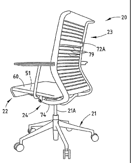
A chair 20 (Fig. 1) embodying the present invention includes a base 21, a seat
22,
and a back 23, with the seat 22 and back 23 being operably supported on the
base 21 by an
underseat control mechanism 24 for synchronous movement upon recline of the
back 23.
Upon recline, the control mechanism 24 moves and lifts the seat 22 upwardly
and
forwardly, such that the back 23 (and the seated user) is automatically
provided with a
weight-activated back-supporting force upon recline. Advantageously, heavier-
weight
seated users receive greater back-supporting force, thus eliminating (or at
least reducing)
7
CA 02528041 2005-12-02
WO 2004/107915 PCT/US2004/017777
the need for them to adjust a tension device for back support when reclining
in the chair.
The seat 22 (and also the back 23) includes a highly comfortable support
surface formed
by a locally-compliant support structure (hereafter called "a comfort
surface") that adjusts
to the changing shape and ergonomic support needs of the seated user, both
when in an
upright position and a reclined position. Specifically, the comfort surface
changes shape
in a manner that retains the seated user comfortably in the chair during
recline, yet that
provides an optimal localized ergonomic support to the changing shape of the
seated user
as the user's pelvis rotate during recline. In addition, the chair 20 avoids
placing an
uncomfortable lifting force under the seated user's knees and thighs, by well-
distributing
such forces at the knees and/or by flexing partially out of the way in the
knee area.
Further, comfort surfaces of the seat 22 and back 23 create a changing bucket
shape (Figs.
2A and 2B) that "grips" a seated user and also actively distributes stress
around localized
areas, such that the seated user feels comfortably retained in the seat 22,
and does not feel
as if they will slide down the angled/reclined back and forward off the seat
during recline,
as described below.
The illustrated control mechanism 24 also has several advantages and inventive
aspects. The control mechanism 24 includes a "booster" mechanism 25 (Fig. 19)
that can
be engaged (with low effort) to provide an even greater back support upon
recline, if the
seated user desires the additional support upon recline. Advantageously, the
control
mechanism 24 has a thin profile and is very cost-effective to manufacture and
assemble,
such that it can be well integrated into chair designs having a thin, side
profile. The
combination of the comfort surface on the back 22 and seat 23 (Fig. 1) with
the control
mechanism 24 provides a surprising and unexpected result in the form of a very
comfortable and supportive "ride" in all positions of the chair, including
upright and
recline positions. The comfortable "ride" is at least partially due to the
fact that, while the
seat that lifts upon recline to provide a weight-activated back support force,
with the seat
22 and back 23 surfaces dynamically changing shape to relieve pressure behind
the seated
user's knees. Also, the comfort surfaces of the seat 22 and back 23 also
create a changing
bucket (see Figs. 2A and 2B) to support the pelvis as it "rolls" and changes
shape during
recline, which counteracts the gravitational forces causing the seated user's
body to want
to slide down the reclined/angled surface of the back 23 and slide forward off
the seat 22.
Also, the booster mechanism 25 on the control mechanism 24 is very easy to
engage or
disengage, (almost like a switch that flips on or off) making it more likely
to be used.
Also, this allows the booster mechanism 25 to be operated by automatic panel
and/or
8
CA 02528041 2005-12-02
WO 2004/107915 PCT/US2004/017777
remote devices, including electronic, mechanical, and other ways.
Advantageously, all
major components of the chair 20, including the control mechanism 24, are
separable and
recyclable, thus facilitating repair, and promoting components and processes
that are
friendly to the environment, while maintaining low cost, efficient assembly,
relatively few
complex parts, and other competitive advantages.
The seat 22 (Figs. 3-4) includes a molded perimeter frame 30 made of nylon or
the
like. The illustrated frame 30 is semi-rigid, but is able to flex and twist a
limited amount
so that the frame 30 gives and moves with a seated user who is reaching and
stretching for
items while doing work tasks. The frame 30 includes a U-shaped rear with
horizontal side
sections 31 connected by a transverse rear section 32, and further includes a
U-shaped
front 33 that connects a front of the side sections 31. It is contemplated
that the perimeter
frame 30 can be a single-piece molding, or a multi-piece assembly. The
illustrated frame
30 defines a continuous loop, but it is contemplated that the frame could also
be U-shaped
with an open front, for example. The U-shaped front 33 includes side sections
34 that
connect to an end of the side sections 31 and extend downward and rearward,
and further
includes a transverse section 35 that connects the side sections 34. The U-
shaped front 33
forms a "U" when viewed from a front, and angles downward and rearward, such
that it
leaves an upwardly open area in a front of the perimeter frame 30 at a
location
corresponding to the underside of a seated user's knees. This allows the
perimeter frame
30 to avoid putting pressure on the bottom of a seated user's knees upon
recline, even
though the seat 22 is raised, as described below.
The side sections 31 include a series of notches 36 (six such notches are
illustrated)
at about 3 to 7 inches rearward of a front end of the side sections 31, or
more preferably 4
to 6 inches. The notches 36 create a flex point, which causes a front section
37 of the side
sections 31 to flex downwardly when pressure is placed on the front end of the
side
sections 31. For example, front section 37 will flex when the front of the
seat 22 is lifted
against the knees of a seated user and the user is lifted, which occurs during
recline of
back 23.
A pair of tracks 38 are attached to the bottoms of the side sections 31
rearward of
the notches 36. The pair of tracks 38 are adapted to slidably engage a seat
support
structure for providing a depth-adjustable feature on the chair 20.
Nonetheless, it is noted
that the present inventive concepts can be used on chairs not having a depth-
adjustment
feature.
9
CA 02528041 2005-12-02
WO 2004/107915 PCT/US2004/017777
The side sections 31 of perimeter frame 30 (Fig. 5) each include
longitudinally-
extending recesses 40, respectively, in their top surfaces for receiving steel
rods 42 (Figs.
3 and 12). The side rods 42 resiliently support and stiffen the side sections
31, particularly
in the area of notches 36. As illustrated (in Figs. 3-4), the recesses 40 are
primarily
located rearward of the notches 36, but also include a front portion that
extends forward
past the notches 36 to provide added resilient support for side sections 31 at
the notches
36. It is noted that the rods 42 can be different shapes or sizes, or multiple
rods can be
used. Also, different materials can be used in the rods 42, if desired, such
as plastic or
composite materials. However, the illustrated rods 42 are linear and made of a
"hard-
drawn spring steel" for optimal strength, low weight, long life, and
competitive cost.
Further, they are mechanically attached into position in their front and rear.
It is
contemplated that the rods 42 could also be insert-molded, snapped in, or
otherwise
secured in place.
The comfort surface of the seat 22 (Fig. 3) (and of the back) are formed by
individual support members 45 with parallel long sections 51 and U-shaped ends
52 that
slidably engage pockets 50 in the side sections 31. There are thirteen pockets
50
illustrated, but it is contemplated that more or less could be included
depending on the
chair design and functional requirements of the design. Further, the multiple
pockets 50
could be replaced with continuous long channels formed longitudinally along
the side
sections 31, if desired. Each pocket 50 includes inwardly facing pairs of
apertures 51'
(Fig. 5) with an "up" protrusion 51 " formed between the apertures 51'. The
ends 52 of
the front eight support members 45 are positioned in and directly slidably
engage the front
eight pockets 50 for limited inward and outward movement, while the ends 52 of
the rear
five support members 45 are carried by bearings 53 in the rear five pockets
50, as
discussed below. The inboard surface of the pockets 50 (i.e. the "up"
protrusion 51
formed between the apertures 51 ') forms a stop for limiting inward sliding
movement of
the ends 52 of the support member 45. By doing this, it limits the downward
flexing of
the long sections 51 with a "sling"-type action when a person sits on the
comfort surface
of the seat 22. Notably, this results in a "soft" stopping action when a
seated user reaches
a maximum flexure of the long sections 51. Part of the reason for the "soft"
stopping
action is the inward flexure of the side sections 31 as the ends 52 bottom out
in the pockets
50, but also part of the "soft" stopping action is due to the independent
action of the
individual support members 45 and due to the paired arrangement of the long
sections 51
on the support members 45. By this arrangement, a seated user remains
comfortable and
CA 02528041 2005-12-02
WO 2004/107915 PCT/US2004/017777
does not feel a sharp and sudden stop that is uncomfortable, even though the
seat 22 is
held to a maximum depression.
Support members 45 (Fig. 7) are hard-drawn spring steel rods (Fig. 11) having
a
circular cross section. The rods (i.e. support members 45) are bent into a
rectangular loop
shape with relatively sharply bent corners, and include parallel/linear long
sections 51 and
flat/short end sections 52. The illustrated end sections 52 have relatively
sharply bent
corners, such that they form relatively square U-shaped configurations. Also,
one of the
illustrated end sections 52 has opposing ends of the wire that abut, but that
are unattached.
It is contemplated that the abutting ends in the one end section 52 could be
welded
together if needed, but this has not been found necessary in the present chair
20,
particularly where bearings 53 are used, as discussed below. It is also
contemplated that
individual linear rods could be used instead of the support member 45 being a
rectangular
loop shape with parallel long sections 51, if desired. In such event, the ends
52 could be
hook-shaped or L-shaped so that they engage the "up" protrusion in the pockets
50 for
limited inwardly movement when a person sits on the seat 22. However, the
interconnection of adjacent pairs of long sections 51 by end sections 52 can
provide an
additional stability and "coordinated" cooperative movement in the pairs that
is believed
to have beneficial effects. In particular, the rear five support members 45
with bearings 53
undergo considerable movement and flexure as a seated user reclines and/or
moves around
in the chair 20, such that bearings 53 with coupled wire sections 51 have been
found to be
desirable with those five support members 45.
As noted above, the rearmost five support members 45 (Fig. 7) include bearing
shoes 53 (also called "bearings" herein) (Figs. 8-10) that are attached to the
end sections
52. The bearing shoes 53 are made of acetal polymer and are shaped to operably
fit into
the pockets 50 for oscillating (inward and outward) sliding movement in a
transverse
direction as a seated user moves around in the chair 20 and as the long
sections 51 of the
support member 45 flex. The bearing shoes 53 include a U-shaped channel 54
shaped to
mateably receive the U-shaped end sections 52. The bearing shoes 53 can
include a
friction tab at locations 55 for snap-attachment to the U-shaped ends 52, if
desired, though
a friction tab is not required per se when a top cap is provided that captures
the bearing
shoes 53 in the pockets 50. Notably, the bearing shoes 53 retain together the
end sections
52 having the wire ends that touch each other even where the abutting ends of
the wire are
not attached directly together by welding.
11
CA 02528041 2005-12-02
WO 2004/107915 PCT/US2004/017777
Right and left top caps 57 (Figs. 13-14) are screw-attached, heat-staked, or
otherwise attached to the side sections 31. The top caps 57 (Fig. 7) include a
body 58
shaped to cover the pockets 50 and operably hold the bearing shoes 53 in
place. A rear of
the body 58 extends laterally and potentially includes a slot 59 to better
cover a rearmost
one of the pockets 50 while still allowing the rearmost wire section 51 to
freely flex (Fig.
7). It is contemplated that the side sections 31 and top caps 57 will both be
made of nylon,
and the bearing shoes 53 made of acetal, because these materials have a very
low
coefficient of friction when engaged with each other. Further, the apertures
51' (Fig. 7)
are oversized to be larger than a diameter of the long sections 51 of the rod
support
members 45, such that there is no drag during flexure of the support members
45 and
concurrent movement of the bearing shoes 53 in the pockets 50.
The illustrated seat 22 (Fig. 1) is covered with a fabric 60, and potentially
includes
a top thin foam or non-woven PET fiber cushion under the fabric 60 on both the
seat 22
and the back 23. However, it is contemplated that the seat 22 and/or back 23
may not
require a foam cushion because, based on testing, the present seat 22 is so
comfortable that
a cushion is not necessary. Further, the space between the wire sections 51
allows the
construction to breathe, so that a seated user does not become sweaty while
resting on the
present chair 20, which can also be a competitive advantage. A thin topper
cushion or
webbing could also be used under the fabric for aesthetics, if desired.
The present arrangement of seat 22 offers several advantages. Assembly is
easy,
and it is difficult to incorrectly assemble the seat. By the present
arrangement, each
different pair of wire sections can be flexed different amounts, and further,
each long
section 51 in a given support member can be flexed more or less (and can be
flexed in a
different direction) than the other long section 51 in the pair. The pockets
50 engage the
bearing shoes 53 and limit their movement, such that they in turn limit
flexure of the wire
long sections 51 to a maximum amount so that the support surface cannot flex
"too far".
Based on testing, the maximum limit of flexure provided by the pockets 54 is a
soft limit,
such that a seated user does not feel an abrupt stop or "bump" as the maximum
flexure is
achieved. It is noted that the present wire long sections 51/52 are all the
same diameter
and shape, but they could be different diameters, stiffnesses, or shapes. The
individual
wire long sections 51 travel to support a seated user's body along discrete
and independent
lines of support, with the wire long sections 51 moving in and out to meet the
body and
support the user. Specifically, as a seated user reclines, the wires move and
flex to create
a shifting new "support pocket" for the seated user. Fig. 2 shows the comfort
surface 60
12
CA 02528041 2005-12-02
WO 2004/107915 PCT/US2004/017777
of the seat 22 as being relatively flat (i.e. position P1, see solid lines)
when there is no
seated user resting on the seat 22. (I.e. The wire long sections 51 of the
support members
45 of the seat 22 are located in a generally horizontal common plane.) When a
seated user
sits in the chair 20 in an upright position, the comfort surface 60 flexes to
a new shape (i.e.
position P2, see phantom lines), which includes an "upright position" support
pocket 63
formed by (and which receives and supports) the protruding bone structure,
muscle, and
tissue of a seated user's hips. As the seated user reclines the back 23 toward
a fully
reclined position (Fig. 2A), the comfort surface 60 flexes to a new shape
(i.e. position P3,
see dashed lines), which includes a newly formed "recline position" support
pocket 65
formed by (and which receives and supports) the protruding portion, muscle,
and tissue of
a seated user's hips. Notably, the support pocket 65 formed in the seat 22
while in the
recline position (Fig. 2B) is located rearward of the support pocket 63 formed
in the seat
22 when in the recline position (see Fig. 2B, where a shape of the seat in the
upright and
reclined positions is overlaid to better show the shape change). This is
caused by a rolling
motion of the hips during recline. The long sections 51 of rod support members
45 are
independent and provide a localized freedom and dynamic of movement able to
comfortably accommodate the rolling activity of the hips of a seated user in a
novel and
unobvious way not previously seen in task chairs.
The back 23 (Fig. 2) also undergoes a shape change, as shown by the comfort
surface 66 in the unstressed position P1 (unstressed, no seated user), the
flexed comfort
surface 66 in the upright stressed position P2 ("upright position" with seated
user), and the
flexed reclined comfort surface 66 in the reclined stressed position P3
("recline position"
with seated user) (Fig. 2A).
The pairs of long wire sections 51 act in a coordinated distributed dynamic
fashion
(primarily in a vertical direction) that provides an optimal comfort surface.
This is a result
of the constrained/limited movement of the bearing shoes 53 on adjacent pairs
of the long
sections 51 of the rod support members 45 and also is a result of the fabric
60 as it
stretches across and covers the long sections 51. Nonetheless, it is noted
that an extremely
comfortable support can be achieved even without the fabric 60, because the
long sections
51 flex in a manner that does not pinch or bind the seated user as the shape
of the support
pocket for their body changes.
It is noted that the long sections 51 in the seat 22 flex and move to provide
support
primarily vertically, but that some of the long sections 51 may have a
horizontal or angled
component of movement and/or may provide a horizontal or angled component of
force to
13
CA 02528041 2005-12-02
WO 2004/107915 PCT/US2004/017777
a seated user. In particular, the long sections 51 located at a front of the
"recline" support
pocket 65 (see wires 51A) tend to engage any depression in the flesh of a
seated user at a
front of the seated user's protruding hip area (i.e. behind the seated user's
thighs and in
front of the seated user's "main" hip area) which tends to securely hold the
seated user in
the seat 22. This occurs regardless of the location of the depression in the
flesh of a
particular seated user, due to the plurality of independently flexible long
sections 51 in the
seat 22. This added holding power appears to be important in preventing seated
users
from feeling like they will slide down an angled back (such as during recline)
and forward
and off the seat. The present inventors believe that this benefit, though
subtle, is a very
important and significant advantage of the chair 20. Notably, even with a
fabric cover,
there may be a horizontal component of force provided by the long sections 51,
limited
only by the movement of the long section 51 under the fabric, the
stretchability of the
fabric, the movement of bearing shoes 53, and the forces generated by the
rolling action of
the seated user's hips.
The operation of the seat 22 is illustrated in Figs. 2-2B. Fig. 2 shows
flexure of a
center of the long sections 51 of the support member 45 between the unstressed
state (i.e.
no seated user, see solid lines P1), and a stressed state (i.e. with a seated
user, see phantom
lines P2) (both in an upright position of the chair 20). Fig. 2A shows the
chair 20 with a
seated user in the chair 20 in the upright position (solid lines) and a
reclined position
(dashed lines). Fig. 2B is a schematic view intended to show the change of
shape in the
comfort surface of the seat 22 between the upright position (see solid lines
P2) and the
reclined position (see dashed lines P3). In Fig. 2B, the seat 22 is compared
as if it did not
move forward upon recline, to better show the change in shape of the "pocket"
in the seat
22 where the seated user's hips are located. Nonetheless, it is noted that the
seat 22 does
move forward during recline in the present chair 20.
The Fig. 7 shows some of the support members 45 with long sections 51
unstressed
(i.e. that are located in an outboard position in their respective pocket 50),
and shows some
of the rod support members 45 with wires 51 flexed (i.e. see the bearing shoes
53 at
location "B" that are located in an inboard position in their respective
pocket 50). Fig. 7
also shows some of the bearing shoes 53 exploded out of the pockets 50 and pre-
attached
to ends of the rod support members 45 (see location "C"). The bearing shoes 53
are ready
to drop downward into the pockets 50, which illustrates a first assembly
technique. Fig. 7
also shows one of the bearing shoes 53 positioned in a pocket 50, with the
associated rod
support member 45 being positioned above it and ready to be moved downward
into
14
CA 02528041 2005-12-02
WO 2004/107915 PCT/US2004/017777
engagement with the recess in the bearing shoe 53 (see location "D"), which
illustrates a
second assembly method.
The back 23 (Figs. 15-17) is similar to the seat 22. Thus, a detailed
description of
the back 23 is not required for an understanding by a person skilled in this
art, since it
would be quite redundant. Nonetheless, a description follows that is
sufficient for an
understanding of the present invention as used on backs, in view of the
discussion
regarding seat 22 above.
Briefly, the back 23 (Figs. 15-17) includes a back perimeter frame 70 composed
of
L-shaped side frame members 71. Top and bottom transverse frame members 72 and
73
are attached to the side frame members 71 to form a semi-rigid perimeter. The
frame 70
can be one-piece or multi-piece. An additional transverse frame member 72A
(Fig. 1) can
also be added, if needed for strength and stability. The side frame members 71
include
forwardly-extended lower sections 74 extending below the bottom transverse
frame
member 73. The lower sections 74 are pivoted to a seat support 122 of the
control
mechanism 24, at location 75, and are pivoted to a flexible arm part of the
control
mechanism 24 at location 141, as described below.
Similar to the seat 22, the back side frame members 71 include pockets 77 (see
seat
frame pockets 50), covers 77' covering the pockets 77 (only a left cover 77'
is shown),
and support members 78 (similar to seat support members 45) are provided as
hard-drawn
spring steel wires with long sections 79 (similar to seat long sections 51).
Several of the
support members 78 have ends that are operably supported by bearing shoes 80
(similar to
bearing shoes 53). Notably, the illustrated back support members 78 come in
two
different lengths because the back 23 has a smaller top width and a larger
bottom width.
(See Fig. 15 and notice the change in position of the pockets 77 at a middle
area on the
side frame members 71.) The top half of the side frame members 71 includes a
plurality
of U-shaped pockets 81 for receiving a wire 79 without a bearing shoe 80. A
top edge of
the top frame member 72 is U-shaped and bent rearwardly for increased neck
support and
comfort to a seated user. Wire strips 83 extend from the top corners of the
back frame 70
to a center point located between a seated user's shoulders, and then extend
downward
into connection to a center of the bottom transverse member 73. When
tensioned, the wire
strips 83 cause the comfort surface of the back (i.e. support members 78) to
take on an
initial concave shape (sometimes referred to as a "PRINGLES potato chip
shape"). This
concave shape increases the comfort by providing a more friendly "pocket" in
the back 23
for a seated user to nest into when they initially sit in the chair 20.
CA 02528041 2005-12-02
WO 2004/107915 PCT/US2004/017777
An adjustable lumbar support 85 (Figs. 15-17) is provided on the back that
includes a pair of bodies 86 slidably connected to an inboard rib 87 on each
of the side
frame members 71. The bodies 86 may (or may not) be connected by a cross
member.
The bodies 86 are located behind the wires 79 adjacent the side frame members
71 and the
wires 79. Handles 88 extend from a rear of the bodies 86 for grasping by a
seated user
reaching behind the back 23. The bodies 86 each include a flange 90 that
engages a
section of the wires 79 as the wire extends in an inboard direction out of the
pockets 77.
By adjusting the bodies 86 vertically, the flanges 90 move behind different
wires 79,
causing a different level of support (since an effective length of the
supported wires are
shortened). Alternatively, the flange 90 can physically engage and bend the
wires 79
when vertically adjusted, if desired. Fig. 17 also shows a maximum of rearward
flexure of
the wires 79, as shown by the line 95.
The present control mechanism 24 (Fig. 18) includes a stationary base support
121
forming a part of the base 21. The seat 22 includes a seat support 122, and
the back 23
includes a back support 123. The seat and back supports 122 and 123 are
operably
attached to the base support 121 as follows. The base support 121 includes an
upwardly-
facing recess 115 covered in part by plate 11 5A. The recess 115 forms a first
pocket 116
for receiving the booster mechanism 25. The recess 115 also forms a tapered
second
pocket 117 that extends vertically down through the base support 121 for
receiving the
tapered top section 118 of a height adjustable post 21A. The illustrated base
21 (Fig. 1)
includes a hub at a bottom of the post 21A, radially extending side sections
extending
from the hub, and castors at ends of the side sections for supporting the
chair 20. A
lockable pneumatic spring is incorporated into the post 21A for providing
counterbalancing support during height adjustment. The post 21A (Fig. 18)
includes a
vertically-actuated release button 21B positioned at a top of the base support
121. In this
location, the release button 21B can be actuated by a handle (not shown)
operably attached
to a top or side of the base support 121, with the handle being pivotally or
rotationally
movable to selectively cause the handle to depressingly engage the release
button 21B and
release the pneumatic spring for height adjustment of the chair. Though one
particular
base is illustrated, it is specifically contemplated that a variety of
different chair bases can
be used in combination with the present chair 20.
The seat support 122 (Fig. 36) is operably supported on the base support 121
by a
front leaf spring 123' and by a pivot mechanism 124 spaced rearward of the
leaf spring
123'. Specifically, the front leaf spring 123' includes a center portion 125
supported on
16
CA 02528041 2005-12-02
WO 2004/107915 PCT/US2004/017777
and attached to an angled front surface 126 (oriented at about 45 ) of the
base support 121
by threaded fasteners, and includes arms 127 having barrel-shaped or
spherically-shaped
bearings 128 on each end that slidably and rotatably fit into cylindrical
recesses 129 in
side members 130 of the seat support 122. The bearings 128 are barrel-shaped
instead of
cylindrically-shaped, so that the bearings 128 permit some non-axial rotation
and axial
sliding as the arms 127 flex, thus helping to reduce high stress areas and
accommodating a
wider range of movement during recline. However, it is contemplated that
different
bearing arrangements are possible that will still meet the needs of the
present inventive
concepts.
The side members 130 are rigidly interconnected by a cross beam 131 (Fig. 36).
The pivot mechanism 124 includes one (or more) pivoted arms 132 that are
pivotally
supported at one end on the base support 121 by a pivot pin 133, and pivotally
connected
to a center of the cross beam 131 at its other end 134 by pivot pin 134" and
pin bearings
134'. Pin bearings 134' are attached to cross piece 131, such as by screws.
The pivot pin
133 is keyed to the arm 132, so that the pivot pin 133 rotates upon movement
of the seat
(i.e. upon recline). Thus, the direction and orientation of movement of the
seat support
122 (and seat 22) is directed by the linear movement of the bearing ends 128
as the arms
127 of leaf spring 123' flex (which is at a 45 angle forward and upward, see
RI in Fig.
38), and by the arcuate movement of the pivoted arm 132 on the pivot mechanism
124 as
the pivot arm 132 rotates (which starts at a 45 angle and ends up near a 10
angle as the
back 23 approaches a full recline position, see R2 in Fig. 38). The distance
of travel of the
front of the seat 22 is preferably anywhere from about %2 to 2 inches, or more
preferably is
about 1 inch upward and 1 inch forward, but it can be made to be more or less,
if desired.
Also, the vertical component of the distance of travel of the rear of the seat
is anywhere
from about 1/2 to 1 inch, but it also can be made to be more or less as
desired. Notably, the
vertical component of seat movement is the component that most directly
affects the
potential energy stored during recline in the chair 20. Restated, the greater
the vertical
component of the seat (i.e. the amount of vertical lift) during recline, the
more weight-
activated support will be received by the seated user during recline.
The back-supporting upright 123 (Fig. 36) includes side sections 135 pivoted
to the
side members 130 of the seat support 122 at pivot location 75, which is about
halfway
between the location of pivot 129 and the pivot 134. The illustrated pivot
location 75 is
about equal in height of the bearings 128 (see Fig. 19), although it could be
located higher
or lower, as desired, for a particular chair design. A rear leaf spring 137
(Fig. 36) includes
17
CA 02528041 2005-12-02
WO 2004/107915 PCT/US2004/017777
a center portion 138 attached to a forwardly angled surface 139 on a rear of
the base
support 121, and includes arms 140 with barrel-shaped or spherically-shaped
bearings 141
that pivotally and slidably engage a cylindrical recess 142 in the side
sections 135 of the
back upright 123. The rear surface 139 is oriented at about a 30 forward
angle relative to
vertical, which is an angle opposite to the rearward angle of the front
surface 126. As a
result, as the side sections 135 of the rear spring 137 are flexed during
recline, the rear
bearings 141 are forced to move forward and downward in a direction
perpendicular to the
rear angled surface 139 (see directions R3 and R4, Fig. 38). Thus, the pivot
75 drives the
seat 22 forward along lines R1 and R2 upon recline, and in turn a reclining
movement of
the back 23 causes the seat support 122 to move forward and upward. As noted
above, the
movement of the seat support 122 is controlled in the front area by the
flexure of the ends
of the front spring 123, which moves the bearings 128 in a linear direction at
a 45 angle
(up and forward in direction "Rl"), and is controlled in the rear area by the
pivoting of the
pivoted arm 132, which is arcuate (up and forward along path "R2"). The pivot
arm 132 is
at about a 45 angle when in the upright rest position (Figs. 19 and 38), and
is at about a
10 angle when in the full recline position (Fig. 39), and moves arcuately
between the two
extreme positions upon recline. The movement of the seat support 122 causes
the pivot
location 136 (Fig. 38) to move forwardly along a curvilinear path. As a
result, the back
upright 123 rotates primarily rearward and downward upon recline (see line
R3), but also
the lower side section 74 moves forward with a coordinated synchronous
movement with
the seat 22, as shown by arrows R1-R2 (for the seat 22) and R3-R5 (for the
back 23) (Fig.
38).
Specifically, during recline, a rear of the seat support 122 initially starts
out its
movement by lifting as fast as a front of the seat support 122. Upon further
recline, the
rear of the seat support 122 raises at a continuously slower rate (as arm 132
approaches the
10 angle) while the front of the seat support 122 continues to raise at a
same rate. The
back 23 (i.e. back upright 123) moves angularly down and forward upon recline.
Thus,
the seat support 122 moves synchronously with the back upright 123, but with a
complex
motion. As will be understood by a person skilled in the art of chair design,
a wide variety
of motions are possible by changing the angles and lengths of different
components.
The booster mechanism 25 (Fig. 19) includes a torsion spring 150 mounted on
the
pivot pin 133 to seat support 121. The torsion spring 150 includes an inner
ring 151 (Fig.
37) keyed to the pivot pin 133, a resilient rubber ring 152, and an outer ring
153 with an
arm 154 extending radially outwardly. A stop member 155 is pivoted to the base
support
18
CA 02528041 2005-12-02
WO 2004/107915 PCT/US2004/017777
121 by a pivot pin 155' (and is keyed to pivot pin 155') and includes a stop
surface 156
that can be moved to selectively engage or disengage the arm 154. When the
stop member
155 is moved to disengage the stop surface 156 from the arm 154 (Fig. 19), the
torsion
spring 150 freewheels, and does not add any bias to the control 120 upon
recline.
However, when the stop member 155 is moved to engage the stop surface 156 with
the
arm 154 (Fig. 20), the outer ring 153 is prevented from movement upon recline.
This
causes the torsion spring 150 to be stressed and tensioned upon recline, since
the pivot pin
133 does rotate upon recline, such that the torsion spring 150 "boosts" the
amount of
energy stored upon recline, . . . thus adding to the amount of support
received by a seated
user upon recline. It is contemplated that the torsion spring 150 will be made
to add about
15% to 20% of the biasing force upon recline, with the rest of the biasing
force being
supplied by the bending of the leaf springs 123 and 137 and by the energy
stored by lifting
the seat support and the seated user upon recline. However, the percentage of
force can, of
course, be changed by design to meet particular functional and aesthetic
requirements of
particular chair designs.
In operation, when the booster mechanism 25 is "off' (Fig. 19), the arm 154
moves
freely as a seated user reclines in the chair. Thus, during recline as the
seat rises and lifts
the seated user, the flexible arms 127 and 140 of leaf springs 123' and 137
flex and store
energy. This results in the seated user receiving a first level of back
support upon recline.
When additional support is needed (i.e. the equivalent of increased spring
tension for back
support in a traditional chair), the booster mechanism 25 is engaged by
rotating stop 155
(Fig. 20). This prevents the arm 154 from moving, yet pivot pin 133 is forced
to rotate by
the arm 132. Therefore, during recline, the rubber ring 152 of the torsion
spring 150 is
stretched, causing additional support to the seated user upon recline. In
other words, the
support provided to the back 23 during recline is "boosted" by engagement of
the booster
mechanism 25.
It is contemplated that several separate torsion springs 150 can be added to
the axle
of pivot 154', and that they can be sequentially engaged (such as by having
their
respective stops 155 engage at slightly different angles). This would result
in increasing
back support, as additional ones of the torsion springs were engaged. (See
Fig. 25.) In
another alternative, it is contemplated that a single long rubber ring 152
could be used and
anchored to the pivot pin 133 at a single location, and that several different
outer rings 153
and arms 154 (positioned side-by-side on a common axle) could be used. As
additional
arms were engaged, the torsional force of the torsion spring would increase at
a faster rate
19
CA 02528041 2005-12-02
WO 2004/107915 PCT/US2004/017777
during recline. It is also conceived that the stop 155 could have steps, much
like the stop
205 (Fig. 21), such that the "booster" torsion spring 150 engages and becomes
active at
different angular points in time during recline. There are also several other
arrangements
and variations that a person of ordinary skill will understand and be able to
make from the
present disclosure. These additional concepts are intended to be covered by
the present
application.
A stop pin 290 (Fig. 37) is provided on the arm 132, and an abutment 291 is
provided on the outer ring 153 of torsion spring 150. The engagement of the
components
290 and 291, and also the engagement of the arm 132 with the base support 121
results in
a positive location of the back 23 in the upright position. The rubber ring
152 can be pre-
tensioned by engagement of the pin 290 and abutment 291. Thus, when the stop
member
156 is engaged, this preload in rubber ring 152 must be overcome prior to
initiation of
recline of the back 23. This results in the elevated pre-tension (see Fig. 24)
whenever the
stop member 155 is engaged (see Fig. 20). In an alternative construction, a
stop pin 290'
is located on the arm 132 and positioned to abut a surface on the chair
control base support
121 as a way of setting the upright position of the back 23.
A backstop 205 (Fig. 21) is formed on the stop member 155. The backstop 205 is
keyed directly to the pivot pin 155' so that it moves with the pivot pin 155'.
There is no
torsion spring element on the illustrated backstop 205. The arm 132 includes a
lever 202
with an abutment surface 203. A backstop 205 is pivoted to pivot pin 155' at a
location
adjacent to the booster stop member 155. The backstop 205 includes a first
abutment
surface 206 and a second abutment surface 207.
A manual control mechanism 220 (Fig. 26) includes a selector device 227
mounted
to base support 121 under the seat-supporting structure 122. The selector
device 227 is
operably connected to pivot pin 155' as noted below for moving the booster
stop 155 and
backstop 205. The backstop 205 does not engage the abutment surface 203 of
lever 202
when the manual control mechanism 220 for booster mechanism 25 and backstop
205 is in
a "home" disengaged position (Figs. 19 and 21). The stop member 155 of booster
mechanism 25 engages and activates the torsion spring 150 when the selector
device 227
is moved to a first adjusted position (Fig. 20). In the first position, the
abutment surface
203 is not yet engaged (Fig. 20). However, when the control 220 is moved to a
second
adjusted position (Fig. 22), the backstop abutment surface 206 engages the
abutment
surface 203 of the lever 202, and the back 23 is limited to only 1/3 of its
full angular
recline. (The backstop 205 can of course have additional intermediate steps if
desired.)
CA 02528041 2005-12-02
WO 2004/107915 PCT/US2004/017777
When the selector device 227 is to a third adjusted position (Fig. 23), the
backstop
abutment surface 207 engages the abutment surface 203 of the lever 202, and
the back 23
is limited to zero recline. The effect of these multiple positions of selector
device 227 are
illustrated by the lines labeled 211-214, respectively, on the graph of Fig.
24.
The combination of the booster mechanism 25 and the backstop 205 results in a
unique adjustable control mechanism, as illustrated in Fig. 24. Literally, the
device
combines two functions in a totally new way - that being a single device that
selectively
provides (on a single member) a backstop function (i.e. the backstop mechanism
202/205)
and also a back tension adjustment function (i.e. the booster mechanism
150/155).
It is contemplated that the pivot pin 155' can be extended to have an end
located at
an edge of the seat 22 under or integrated into the seat support 122. In such
case, the end
of the pivot pin 155' would include a handle for grasping and rotating the
pivot pin 155'.
However, the selector device 227 of the manual control mechanism 220 (Figs. 26-
27) can
be positioned anywhere on the chair 20.
A manual control mechanism 220 (Fig. 26) includes a Bowden cable 251 having a
sleeve 221 with a first end 221' attached to the base support 121, and an
internal
telescoping cable 222 (Fig. 27) movable within the sleeve 221. A wheel section
223 is
keyed or otherwise attached to the pivot pin 155' of the back booster and
backstop
mechanism, and an end 224 of the cable 222 is attached tangentially to a
perimeter of the
wheel section 223. (Alternatively, if the diameter of the pivot pin 155' is
sufficiently
large, the cable end 224 can be connected tangentially directly to the pivot
pin 155'.)
Optionally, a spring 225 can be used to bias the wheel section 223 in
direction 225',
pulling the cable in the first direction 225. However, spring 225 is not
required where the
cable 222 is sufficient in strength to telescopingly push as well as pull. The
cable sleeve
221 includes a second end attached to the seat support 122, such as on the end
of a fixed
rod support 226 extending from the seat support 122. A selector device 227 is
attached
near an end of the rod support 226 for operating the cable 222 to select
different back
supporting/stopping conditions.
The selector device 227 (Fig. 28) operates very much like a gearshift found on
a
bicycle handle bar for shifting gears on the bicycle. The selector device 227
is also not
unlike the lumbar force-adjusting device shown in patent 6,179,384 (minus the
gears 56
and 56'). It is noted that a patent entitled "FORCE ADJUSTING DEVICE", issued
January 30, 2001, Patent No. 6,179,384, discloses a clutch device of interest,
and the entire
21
CA 02528041 2005-12-02
WO 2004/107915 PCT/US2004/017777
contents of patent 6,179,384 are incorporated herein by reference in its
entirety for the
purpose of disclosing and teaching the basic details of a sprag clutch and its
operation.
The illustrated selector device 227 (Figs. 28-30) includes a housing 228 fixed
to
the rod support 226 with an inner ring section 229 attached to the rod, and an
annular
cover 230 rising from the ring and forming a laterally-open cavity 231 around
the ring
229. Detent recesses 237 are formed around an inside of the cover 230. A one-
piece
plastic molded rotatable clutch member 233 including a hub 242 is positioned
in the cavity
231 and includes a first section 234 attached to the cable end 221 ". The
rotatable clutch
member 233 further includes a clutch portion 235 integrally formed with hub
242. A
handle 236 is rotatably mounted on an end of the support 226 and includes
protrusions 238
that engage the clutch 235 to control engagement with the detent recesses 237
as follows.
The clutch portion 235 (Fig. 28) includes one or more side sections 240
(preferably
at least two side sections 240, and most preferably a circumferentially
symmetrical and
uniform number of side sections, such as the illustrated six side sections)
having a resilient
first section 241 that extends at an angle from the hub 242 to an elbow 243
that is in
contact with the detent recesses 237, and a second section 244 that extends in
a reverse
direction from the end of the first section 241 to a free end 245 located
between the hub
242 and the detent recesses 237. Each free end 245 includes a hole 248. The
handle 236
includes a clutch-adjacent section 246 that supports the protrusions 238 at a
location where
the protrusions 238 each engage the hole 248 in the associated free end 245 of
every side
section 240. Due to the angle of the first sections 241 (Fig. 3 1A, see arrow
280) relative to
the inner surface of the housing that defines detents 237, the first sections
241
interlockingly engage the detent recesses 237 against the bias of the spring
225 as
communicated by the tension in cable 222 (see arrow 281), preventing movement
of the
clutch 235 when it is biased in direction 249 (Fig. 31) by the hub 242. Thus,
when handle
236 is released, the clutch 235 again locks up against the force 281 of spring
225 (Fig. 27)
as communicated by cable 222 to the clutch 235. However, when the handle 236
is
grasped and moved in the rotational direction 283 (Fig. 3 1A) relative to
housing 228, the
handle protrusions 238 pull the second section 244 to thus pull the first and
second
sections 241 and 244 so that the rotatable member 230 (and the clutch 231)
rotates. When
the handle 236 is moved in a rotational direction 282 (Fig. 31A), the handle
protrusions
238 push the second section(s) 244 at a low angle relative to the detent
recesses 237, such
that the second sections 244 (and first sections 241) slip out of and over the
detent recesses
237 (Fig. 31B), allowing the rotatable member 230 (and clutch 231) to
adjustingly move
22
CA 02528041 2005-12-02
WO 2004/107915 PCT/US2004/017777
in direction 281. Thus, the present arrangement allows adjustment in either
direction, but
interlocks and prevents unwanted adjustment in a particular direction against
a spring
biasing force.
It is noted that actuation of the booster mechanism 25 and the backstop 205 is
particularly easily accomplished, since the actuation action does not require
overcoming
the strength of a spring nor of overcoming any friction force caused by the
spring 150.
Further, the actuation action does not require movement that results in
storage of energy
(i.e. does not require compressing or tensioning a spring). Thus, a simple
battery-operated
DC electric motor or switch-controlled solenoid would work to operate the
booster
mechanism 25 and/or the backstop 205. Fig. 26 illustrates a housing 300
supporting a
battery pack and electric rotary motivator (such as a DC motor), and includes
an end-
mounted switch. Fig. 27A illustrates a linear motivator 301 operably connected
to cable
222, and also illustrates a rotary motivator 302 connected to axle 155'. Since
the
movement of the booster mechanism 25 and the backstop 205 requires only a very
small
amount of energy with minimal frictional drag, it can be accomplished without
a need for
a large energy source. Thus, a small battery-operated device would work well
for a long
time before needing recharge of its battery.
The illustrated control mechanism 24 above has front and rear leaf springs
used as
flexible weight bearing members to support a seat and back for a modified
synchronous
movement, and has a pivoted link/arm that assists in directing movement of a
rear of the
seat. However, the present arrangement can also include stiff arms that are
pivoted to the
base support 121, or can include any of the support structures shown in U.S.
Patent
Application Publication No. 2004-0051362, published on March 18, 2004,
entitled
"SEATING UNIT HAVING MOTION CONTROL", the entire contents of which are
incorporated herein in their entirety. Also, a "booster" mechanism 25 provides
added
biasing support upon recline when a stop is engaged. However, it is
contemplated that a
continuously adjustable biasing device such as a threaded member for adjusting
a spring
tension or cam could be used instead of the booster mechanism 25.
Since the seat support 122 raises upon recline, potential energy is stored
upon
recline. Thus, a heavier seated user receives greater support upon recline
than a
lightweight seated user. Also, as a seated user moves from the recline
position toward the
upright position, this energy is recovered and hence assists in moving to the
upright
position. This provides a weight-activated movement seat, where the seat lifts
upon
recline and thus acts as a weight-activated motion control. (I.e. The greater
the weight of
23
CA 02528041 2005-12-02
WO 2004/107915 PCT/US2004/017777
the seated user, the greater the biasing support for supporting the user upon
recline.) It is
noted that a variety of different structures can provide a weight-activated
control, and still
be within a scope of the present invention.
MODIFICATION
A modified chair or seating unit 20B (Figs. 40-42) includes changes and
improvements from that of chair 20. In order to minimize redundant discussion
and
facilitate comparison, similar and identical components and features of the
chair 20B to
the chair 20 will be identified using many of the same identification numbers,
but with the
addition of the letter "B".
The chair 20B (Fig. 40) includes a base 21B, a seat 22B, and a back 23B, with
the
seat 22B and back 23B being operably supported on the base 21B by an underseat
control
mechanism 24B for synchronous movement upon recline of the back 23B. As with
chair
20, upon recline of chair 20B, the control mechanism 24B moves and lifts the
seat 22B
upwardly and forwardly, such that the back 23B (and the seated user) is
automatically
provided with a weight-activated back-supporting force upon recline. The seat
22B (and
also the back 23B) includes a highly comfortable support surface formed by a
locally-
compliant support structure (hereafter called "a comfort surface") that
adjusts to the
changing shape and ergonomic support needs of the seated user, both when in an
upright
position and a reclined position. Specifically, the comfort surface changes
shape in a
manner that retains the seated user comfortably in the chair during recline,
yet that
provides an optimal localized ergonomic support to the changing shape of the
seated user
as the user's pelvis bones rotate during recline. In addition, the chair 20B
avoids placing
an uncomfortable lifting force under the seated user's knees and thighs, by
well-
distributing such forces at the knees and/or by flexing partially out of the
way in the knee
area. Further, comfort surfaces of the seat 22B and back 23B create a changing
bucket
shape (similar to that shown in Figs. 2A and 2B) that "grips" a seated user
and also
actively distributes stress around localized areas, such that the seated user
feels
comfortably retained in the seat 22b, and does not feel as if they will slide
down the
angled/reclined back and forward off the seat during recline, as described
below.
The chair control mechanism 24B (Fig. 43) includes a booster/back stop
selector
device 227B with a handle 300 rotatable about a first axis 301 for selectively
moving the
backstop and booster mechanisms (see Figs. 19-23) (components 156 and 205)
between
the multiple positions illustrated in Figs. 19, 20, 22, and 23. The control
mechanism 24B
24
CA 02528041 2005-12-02
WO 2004/107915 PCT/US2004/017777
further includes a second control device 302 with a radially-extending lever
handle 303
rotatable about a rod 304 forming a second axis 304'. The second axis extends
parallel to
but is spaced from the first axis 301. The handle 303 is made to be positioned
adjacent the
handle 300, and includes a projection that engages the handle 300 to form a
stop surface to
limit back rotation of the handle 303. On an inner end of the rod 304 (Fig.
48) is a radially
extending finger 305. The base 21B (Fig. 45) includes a releasable self-
locking pneumatic
spring 307 having two fixed tabs 308 for engaging a sheath on a cable sleeve,
and a side-
activatable lever 309 that operably engages an internal release button in the
spring 307. A
side-activatable pneumatic spring such as pneumatic spring 307 is commercially
available
in commerce and need not be described in detail in this application. (See Cho
patent
6,276,756.) A cable assembly (Fig. 48) includes a cable 310 connected at one
end 311 to
the finger 305 and at another end 312 (Fig. 45) to the lever 309. The cable
assembly
further includes a sleeve 313 (Fig. 48) that is connected to the base support
121B near the
handle 303, and that extends to and is connected to the tabs 308 (Fig. 45) on
the pneumatic
spring 307.
As shown in Figs. 44-46, the base support 121 B is inverted from the base
support
121. Specifically, the base support 121B (Fig. 46) includes a similar cavity
and internal
surfaces and structure for supporting the levers, stops, and booster
mechanisms within the
base support 121B, similar to base support 121. However, the front portion
116B of the
cavity in base support 121B opens downwardly, and the cover 115B engages a
bottom of
the base support 121B. An upright arm 315 (Fig. 45) is attached to the stop
member 155B
and extends up through a top aperture 155$' in the base support 121B. An end
316' of a
cable 316 is connected to the arm 315 and extends to a tangential connection
on the
booster/back stop selector device 227B (Fig. 48), such that when the handle
300 is rotated,
the cable 316 is pulled (and/or pushed) ... and hence the stop member 155B is
moved to a
selected position. (See Figs. 19, 20, 22 and 23).
The laterally-extending arms 127B of the front spring 123B' (Fig. 47) include
a tab
320 that non-removably snap-attaches into a spherical bearing 321. The seat
support 122B
(Fig. 45) includes a pair of side frame members 322 and a transverse cross
piece 323
rigidly connecting the opposing side frame members 322. Each side frame member
322
includes a bore 324, which, if desired, includes a bearing sleeve 325. The
spherical
bearings 321 on the ends of leaf springs 123B' each rotatably and
telescopingly slidingly
engage the sleeve 325/bore 324 to accommodate non-linear movement of the
spherical
bearing 321 during recline of the back 23B. Hole 75B (Fig. 47) receives a
pivot pin that
CA 02528041 2005-12-02
WO 2004/107915 PCT/US2004/017777
rotatably connects the respective side sections 135B of the back supporting
upright 123B
to the seat support 122B. A flange 327 forms a slot 328 along a top of the
side frame
members 322.
Each seat 22B (Fig. 43) includes a bracket 480 that forms a mounting socket
481
on seat side frame members 322 for receiving and fixedly supporting an "L-
shaped"
armrest support structure 482 (Fig. 42) and T-shaped armrest 483.
The seat 22B is depth adjustable, and includes a pair of seat carriers 330
(Fig. 45)
attached to each side for sliding depth adjustment. Specifically, the seat
carriers 330 each
include a body 331 (Fig. 65) adapted to slidably engage a top of the side
frame members
322 of the seat support 122B, and further include a lateral flange 332 that
fits into and
slidably engages the slot 328 for providing fore/aft depth adjustment of the
seat 22B. The
seat 22B is captured on the seat support 122B because flanges 332 on the right
side and
left side seat carriers 330 face in opposite directions. A series of notches
333 in the top
inboard side of the seat carriers 330 are engaged by a latch 334 mounted on
the seat
carriers 330, the latch 334 being movable downward into an engaged position to
engage a
selected notch 333 for holding the seat 22B at a selected depth position. The
latch 334 is
movable upward to disengage the notches 333, thus permitting horizontal depth
adjustment of the seat 22B. It is contemplated that the latch 334 can be a
variety of
different constructions, such as a blade mounted for vertical movement on the
seat 22B, or
a bent wire rod that when rotated has end sections that move into and out of
engagement
with the notches 333. It is contemplated that other latching and adjustment
arrangements
can also be constructed.
In the illustrated chair design, the latch 334 is two-sided (Fig. 63) and is
adapted to
engage both sides of the seat 22B to prevent racking and unwanted angular
twisting and
rotation in the horizontal plane of the seat 22B. In other words, it is
preferable that both
seat carriers 330 be fixed to their respective side frame members 322 when
latched to
provide a stable seat arrangement that does not torque and twist in an
undesirable
unbalanced manner when a seated user is attempting to recline.
The illustrated latch 334 (Fig. 63) is actuated by a U-shaped bent wire
actuator
334' which includes a transverse handle section 470 forming a handle graspable
under the
seat front section 388, and includes a pair of legs 471 and 472. Each leg 471
(and 472)
(Fig. 64) fits into a space between sidewall 365 and side section 359 (and
between
sidewall 366 and side section 359) of seat 22B. An annular groove 473 (Fig.
64) fits
mateably into a notch 474 in a rib 475 between walls 365 and 366 to form a
pivot for leg
26
CA 02528041 2005-12-02
WO 2004/107915 PCT/US2004/017777
471 (and 472). The latch 334 is pivoted on an axle 476, and includes a
latching end 477
shaped to move into and out of engagement with notches 333, and includes a
second end
478 operably connected to a rear tip 479 of leg 471 in direction "D". When
handle section
470 is moved up, side legs 471 and 472 pivot at rib 475, such that leg tip 479
moves down.
When leg tip 479 moves down, latching member 334 pivots about pivot 476 to
lift latching
end 477 out of notches 333. A depth of seat 22B can then be adjusted. One or
more
resilient springs 480 (Fig. 63) located between transverse handle section 470
and seat front
section 388 bias section 470 downwardly, causing latching tip 479 to again
engage a
selected notch 333 when handle section 470 is released.
As noted above, the chair control mechanism 24B (Fig. 43) includes a
booster/back
stop selector device 227B with a handle 300 rotatable about a first axis 301
for selectively
moving the backstop and booster mechanisms (see Figs. 19-23) (components 156
and 205)
between the multiple positions illustrated in Figs. 19, 20, 22, and 23. More
particularly, a
tubular support 340 (Fig. 48) is attached to the outboard side of the right
side frame
member 322. A bearing sleeve 341 is positioned in the tubular support 340
along with a
coiled compression spring 342, a crown-shaped detent ring 343 with pointed
axial tips
344, and the handle 300. A rod 345 extends from the handle 300 through the
components
343, 342, and 340 to an inside of the side frame member 322. The handle 300
includes
teeth-like projections 346 (Fig. 49) that engage the axial tips 344 of the
detent ring 343,
and the detent ring 343 is biased axially in an outboard direction so that the
tips 344
continuously engage the projections 346. Further, the detent ring 343 is keyed
to the
tubular support 340 so that the detent ring 343 cannot rotate, but is able to
telescope
axially. The tips 344 and projections 346 include angled surfaces so that upon
rotation of
the handle 300, the detent ring 343 will move axially inward against the bias
of spring
342, and then snap back outwardly as the tips 344 fit between adjacent
projections 346,
thus permitting rotation of the handle 300 in directions 347. This arrangement
causes the
handle 300 to move with a detented rotation. The illustrated arrangement
includes four
projections 346 on the handle 300, and sixteen tips on the detent ring 343,
but it is
contemplated that more or less of each can be used. It is contemplated that
the handle 300
can include markings 349 to identify its function, and that any of the handle
shapes
commonly used in the chair art can be incorporated into the illustrated
design.
A lever 351 (Fig. 48) extends from an inner end of the rod 345, and is
operably
connected to one end 353 of the cable 316. Recall that the other end 316'
(Fig. 45) of the
27
CA 02528041 2005-12-02
WO 2004/107915 PCT/US2004/017777
cable 316 is connected to the arm 315 of the stop member 155B of the booster
and back
stop engaging member 155B.
The seat 22B (Fig. 50) includes a seat frame 357 comprising an upper frame
component 358 and right and left seat lower frame components 359 and 360
attached to
right and left sides of the upper frame component 358. The lower frame
components 359
and 360 are attached directly to the top of the seat carriers 330 mentioned
earlier (Fig. 45),
or can be integrally formed to incorporate the features of the illustrated
carriers 330. The
support members 45B (Fig. 50) comprise single wires with down-hooks formed at
each
end, as described below.
The lower frame components 359 and 360 (Fig. 50) are mirror images of each
other, and accordingly only the lower frame component 359 will be described.
The lower
frame component 359 is a plastic molded component having a bottom wall 362,
front and
rear end walls 363 and 364, and three longitudinal walls 365-367. The outer
wall 365
formed an aesthetic and structural outer surface. The intermediate wall 366
includes a
plurality of apertures bosses 368 for receiving screws (not shown) to attach
the upper and
lower frame components 358 and 359/360 together. The inner wall 367 includes a
plurality of vertically open slots 369 that extend from its top surface to
about halfway
down into its height, and further includes parallel walls 370 and 371 that
extend from wall
367 to wall 366 on each side of the slots 369. A recess or pocket 50B is
formed between
each of the parallel walls 370 and 371 for receiving the end sections 52B, as
described
below. The inboard side of the intermediate wall 366 forms a first stop
surface 372 (Fig.
52), and the outboard side of the inner wall 367 forms a second stop surface
373 with an
angled ramp surface 374 extending inwardly and downwardly away from the second
stop
surface 373.
Each support member 45B (Fig. 50) comprises a single wire of the same type
wire
as support member 45 described above. Each support member 45B has a long
section 51B
and has L-shaped down-formed end sections 52B forming hooks. The long section
51B is
linear and extends generally horizontally through a bottom of the slots 369
when in an
installed position without a user setting on the seat 22B. The end sections
52B are linear
and extend downwardly into the pockets 50B. When in an installed position
without a
user setting on the seat 22B (see solid lines in Fig. 52), the end sections
52B abut the outer
(first) stop surface 372, causing the wire long section 51B to have a slight
downward bow
in its middle area at location 374'. This provides a pretension and pre-form
in the wire
support member 45B. When a user sets on the seat 22B (see dashed lines in Fig.
52), the
28
CA 02528041 2005-12-02
WO 2004/107915 PCT/US2004/017777
long section 51B bends until the end sections 52B engage the inboard (second)
stop
surface 373. This limits further bowing or bending of the long section 51B.
Further, the
angled ramp surface 374 provides additional support to the end portions of the
long
section 51B, inboard from the end sections 52B, such that the effective length
of the long
section 51B is reduced. This results in the support member 45B having a preset
maximum
bend that is limited by the inner stop surface 373 (i.e. a sling type effect),
and further is
limited by a shorter effective length of the long wire section 51B (which
feels stiffer).
Both of these circumstances cause a soft bottoming out as the wire support
member 45B
deflects to a maximum bend. At the same time, the wire support member 45B can
bend at
any location, more than only at their center point, such that the seated user
receives a
particularly comfortable and ergonomic support.
The seat 22B also includes a cushion assembly 375 (Fig. 40) comprising a
cushion
and an upholstery or cloth covering. It is contemplated that the supports 45B
are so
flexible and comfortable that the cushion can be eliminated. Alternatively, a
cushion
assembly 375 can be used that is preferably anywhere from 1/4 inch to 1 inch
in thickness.
The upholstery covering can be any material, but preferably should allow some
(though
not too much) elastic stretch and give to accommodate the shape changes
permitted by the
individual movement of the support members 45B.
Where the cushion assembly 375 is sufficiently elastic and resilient, the
cushion
assembly 375 can include front and rear hook-like formations that permit it to
be hook-
attached to a front and a rear of the seat support structure (i.e. frame 30B).
(See the
discussion of Figs. 70-71 below.)
It is contemplated that, instead of the support members 45B comprising a
single
long wire with bent ends, that the support members 45B can be made to include
long
resilient wires or stiff members, supported at their ends by hinges to the
side frame
components, with the axis of rotation of the hinges extending forwardly and
being at or
slightly below the long resilient wires. For example, Fig. 52A discloses seat
having a
modified lower frame component 359 made to include a strap 380 supported by a
downwardly offset living hinge 381 at a bottom of where the second (inner)
stop surface
373 would be. The strap 380 has a groove shaped to receive a straight length
of wire 382.
When there is no seated user, the wire 382 extends horizontally, and the
living hinge 381
moves to allow the inner wall 367' to move to a normal raised position. When a
person
sits on the seat, the living hinge 381 flexes, causing the wall 367' to tip
inward and
29
CA 02528041 2005-12-02
WO 2004/107915 PCT/US2004/017777
downward. (See dashed lines.) This results in an action and movement similar
to that
noted above in regard to seat 22B.
The seat upper frame component 358 (Fig. 50) includes a perimeter frame
portion
with side sections 385 and 386, rear section 387 and under-the-knee
"waterfall" front
section 388 defining a large opening 389 across which the support members 45B
extend.
The side sections 385 and 386 screw-attach to the lower side frame components
359 and
360, and both stiffen the side frame components 359 and 360 and also capture
the end
sections 52B in the pockets 50B. The rear section 387 forms a stiff rear area
of the seat
22B. The front section 388 extends forwardly 3 to 6 inches, and forms a front
"waterfall"
front surface that comfortably supports the thigh area of seated users of the
chair 20B.
Multiple slots 390 and/or stiffening ribs provide an optimal stiffness so that
the front
section 388 will resiliently flex but provide adequate support and a good feel
in both the
upright and reclined positions of the chair 20B. Fore-aft leaf springs and
transverse
leaf springs can be added to optimize anyone of the sections 385-388. In
particular, it is
contemplated that fore/aft springs will be added to help support the
transition area at ends
of the front section 388 near a front of the side sections 385-386.
The illustrated reinforced-plastic springs 490 (Fig. 63) are pultruded flat
leaf-
springs made to flex without taking a permanent set. They fit snugly into a
recess in the
upper frame component 358, and are held thereagainst by the lower frame
components
359. It is contemplated that they will have a flat horizontal cross-sectional
shape, and that
they will extend forward of the front end of the side sections 359, but other
configurations
and arrangements are possible, while still accomplishing the same function.
The structure of back 23B (Figs. 53-54) is not dissimilar to the structure of
the seat
22B. Hence a detailed repetitious description is not required. Nonetheless, it
is noted that
the back 23B includes a back perimeter frame 70B with upright side sections
400, 401, top
transverse section 402 and bottom transverse section 403 defining a large open
area 404.
A bottom of the side sections 400 and 401 extend forwardly to form forwardly-
extending
side leg sections 135B, and are pivotally connected to the seat side sections
at pivot 75B.
The upright side sections 400 and 401 include a bottom wall 405 (Fig. 53), end
walls 406
and 407, and inner and outer walls 408 and 410. Half-depth slots 411 (Fig. 54)
are formed
in inner wall 408, and parallel walls 412 and 413 extend between the inner and
outer walls
408 and 410 on each side of each slot 411. A pocket 77B is formed on the
bottom wall
405 between the parallel walls 409-410. Bosses 409' are formed between the
inner and
outer walls 408 and 410, and are supported by a short intermediate wall 409
that extends
CA 02528041 2005-12-02
WO 2004/107915 PCT/US2004/017777
between adjacent ones of the parallel walls 412 and 413 (at locations not
interfering with
the recesses or pockets 77B). Support members 78B (similar to support members
50B in
the seat 22B) are positioned on the back 23B, and each include a long wire
section 414
that extend into the slots 411, and L-shaped bent end sections 415 that extend
down into
the pockets 77B. The movement of end sections 415 within the pockets 77B is
similar to
that described above in regard to the seat 22B. In the rest position, the end
sections 415
abut outer surfaces 417 of the pockets 77B, thus holding the wires in a
partially bent
condition. When a seated user rests in the chair and leans on the back, the
long wire
sections 414 flex, until the end sections 415 move abuttingly into the inboard
stop surface
418, thus limiting any further flex of the wire support members 78B. Front
covers 420
and 421 (Fig. 53) are attached to a front of the back upright side sections
400 and 401.
The covers 420 and 421 both stiffen the side sections 400 and 401, and also
hold the end
sections 415 within the pockets 77B.
A cushion assembly 375' (Fig. 40) similar to that described above in regard to
the
seat 22B is attached to the back frame 70B. It can be attached in different
manners. It is
contemplated that one optimum method is to stretch and hook attach the cushion
assembly
to the top and bottom transverse frame sections 402 and 403. It is
contemplated that a
person skilled in the art will be able to use and adapt the attachment
structure shown in
Figs. 70-71 to the top and bottom of the back 23B for attaching the back
cushion assembly
375', and to the front and rear of the seat 22B for attaching the seat cushion
assembly 375.
Thus, a detailed description of each is not required.
As shown in Fig. 71, the bottom frame section 403 of the back frame 400
includes
a pair of ridges 528 and 529 that define a downwardly-facing rectangularly-
shaped pocket
or channel 530 that extends continuously across a width of the back frame 400.
A detent
channel 531 (or ridge if desired) is formed parallel the channel 530 along an
outside front
surface of the bottom frame section 403. The cushion assembly 375' includes a
U-shaped
extruded plastic attachment clip 532, including a flat leg 533, a barbed leg
534, and a
resilient section 535 connecting the legs 533 and 534. The legs 533 and 534
are spaced
apart to receive and matably engage the forward ridge 529. A detent protrusion
536 is
biased into engagement with the detent channel 531 by the resilient section
535.
The cushion assembly 375' further includes a sheet of upholstery material 540
connected to the flat leg 533 by a strip of elastic sheet material 541.
(Alternatively, the
elastic sheet material 541 can be eliminated, and the upholstery material 540
attached
directly to the flat leg 533, if testing shows that the added elastic stretch
from the sheet
31
CA 02528041 2005-12-02
WO 2004/107915 PCT/US2004/017777
material 541 is not required.) Specifically, one edge of the elastic sheet
material 541 is
sewn to the flat leg 533 of clip 532 by stitching 542, and an opposite edge is
sewn to the
upholstery material 540 by stitching 543. The strip 541 extends completely
across a width
of the back frame 400. Different methods are known for attaching and sewing
the
upholstery material 540 to the strip 541, and of for attaching and sewing the
strip 541 to
the flat leg 533, such that only a single simple seam is illustrated. It is
contemplated that in
a preferred form, in addition to the sheet material 541, a foam layer 544 and
stable backing
sheet 545 will be attached to the cushion assembly 375', although this is not
required.
To attach the cushion assembly 375' to the back frame 400, the flat leg 533 of
the
extruded clip 532 of the cushion assembly 375' is pressed into the channel 530
of the
bottom frame section 403 of the back frame 400, with the opposing leg 534
frictionally
engaging an outer front surface of the bottom frame section 403. The combined
thickness
of the elastic sheet material 541 and the flat leg 533 captured within the
channel 530,
along with the detent protrusion 535 engaging the detent channel 531, form a
strong secure
connection that retains and holds the cushion assembly 375' to the back frame
400. It is
noted that the sheets 540 and 541 overlay onto the barbed leg 534 when the
cushion
assembly 375' is fully installed onto the back frame 400 (see the arrow 548 in
Fig. 71, and
see the assembly of Fig. 70). Since the barbed leg 534 has a thickened cross
section, a
tension in the sheets 540 and 541 further biases the detent protrusion 535
into engagement
with the detent channel 531. Also, the thickened section of the barbed leg 534
can help
hide the stitching, by providing a space to receive the stitched area and to
receive the
multiple thicknesses of pleats in the stitched area.
A rail 424 (Fig. 55) is formed on a front of an inwardly-directed flange 425
on the
side sections 400 and 401. The rail 424 extends vertically about half to two-
thirds of a
length of the side sections 400 and 401, and includes a top termination or end
426 that
forms a access port for engaging the rail 424. Different accessories can be
mounted on the
rail 424. For example, a lumbar device 427 and a headrest support 428 (Fig.
40) are
illustrated.
The illustrated lumbar device 427 (Fig. 55) includes a plastic body 430 that
extends around flange 425, a pair of hook-shaped retainer fingers 431 that
slidably engage
the rail 424, and a handle 432 that extends from body 430 opposite the
retainer 431. A
pair of detent bumps or recesses 433 are formed on the body 430 adjacent the
retainer
fingers 431, and are adapted to detentingly engage successive wire support
members 78B
as the lumbar device 427 is moved up and down. Interestingly, the lumbar
device 427 can
32
CA 02528041 2005-12-02
WO 2004/107915 PCT/US2004/017777
be adjusted downwardly to a non-use storage position (see Fig. 59), where the
lumber
device 427 is so low that it is effectively disabled since it is no longer
effective to provide
lumbar support to a seated user. As the lumbar device 427 is moved upwardly,
the area of
body 430 adjacent the detent bumps 433 supports the long wire sections 414 at
locations
inboard of the inner wall 408. (See Fig. 56.) Thus the effective bendable
length of the
long wire sections 414 is foreshortened, as illustrated by Figs. 56-57. Thus,
the added
lumbar support comes from less flexing of the long wire sections 414, and does
not come
from a forced shape change to the lumbar support area on the back 23B
(although it could
also be designed to create a shape change in the lumbar, if desired). This
"flat" adjustment
is believed to have good ergonomic benefits, since a seated user receives the
added lumbar
support that they desire, yet their back and upper torso are not forced to
take on a different
body shape.
Another important discovery is the independent action of the right and left
lumbar
devices 427. By adjusting the right and lumber devices 427 to a same height, a
maximum
lumbar support force can be achieved in a particular area (i.e. two wire long
support
sections 414 are supported). By adjusting the right and left lumbar devices
427 to
different heights, the lumbar support area is effectively enlarged (i.e. four
wire long
support sections 414 are supported). Further, where one lumbar device 427 is
adjusted
high and the other is adjusted relatively low but still in an effective lumbar
supporting
area, the lumber devices 427 provide an exceptionally wide range of non-
uniform
adjustability, i.e. more to the right in one area and more to the left in
another area. It is
also conceived that different lumbar devices 427 can be provided, such that a
user can
select the lumbar support that they desire by choosing an appropriate lumber
device 427.
Even if a single one of the illustrated lumbar devices 427 is used (e.g. if
the other
side lumbar support device 427 is parked in the disabled position), the seated
user does not
feel an unbalanced lumber support from the back 23B. However, it is conceived
that the
present lumbar device 427 can be designed to appreciably shift the lumbar
support to one
side (i.e. the long wire section 414 is supported only on one side, such that
more lumber
support is provided on one side of the chair and less support on the other
side). This
initially may seem to be undesirable since the lumbar support is unbalanced.
However,
testing has shown that some seated users want and even prefer an unbalanced
lumbar
support. This may be particularly true for users having a curved spine, where
non-uniform
support has beneficial health effects. Also, users may want different lumbar
support at
33
CA 02528041 2005-12-02
WO 2004/107915 PCT/US2004/017777
different times as they sit and/or recline sideways in unsymmetrical
positions, and as they
turn and shift to different unbalanced positions in their chairs.
The illustrated back frame 70B (Fig. 67) has a unique construction that
facilitates
assembly. The bottom 500 of side sections 400 and 401 are hollow and each
define an
arcuate cavity 501. Side leg sections 135B include an arcuately-shaped body
502
configured to telescopingly slide into cavity 501. Once telescoped together,
holes 503 and
504 on the bottoms 500 and side leg sections 135B align. Pivot pins are
extended through
holes 503 and 504 to form pivot 75B, and both secure the components (bottoms
500 and
side leg sections 503 and 504) together, but also act as pivots for the back
frame 70B on
the seat 22B.
The side frame members 322 of the seat 22B include a pair of arcuate recesses
510
(Figs. 48 and 67) that extend partially circumferentially around the hole 75B.
The
recesses 510 and holes 75B form a bow-tie-shaped feature. An inboard side of
the side leg
sections 135B include a pair of opposing protrusions 511 (Fig. 67) that fit
into recesses
510. The protrusions 511 engage opposing ends of the recess 510 as the back
frame 70B
(i.e. back 23B) is rotated around pivot pins 505 between upright and fully-
reclined
positions, thus acting as a stop to set a maximum recline position of the back
23B.
A headrest 440 (Fig. 60) can be added to the chair 20B. The headrest 440
includes
a headrest support 441 and a vertically and angularly adjustable headrest
assembly 442.
The headrest support 441 includes a center tube 443 and right and left arms
444 and 445
that extend to side sections 400 and 401 of the back frame 70B. The center
tube 443 is
positioned rearward of the transverse upper frame section 402 and includes a
tab 443'
configured to securely engage and be attached to the top frame section 402 of
the back
frame 70B. Alternatively, it is contemplated that the tube 443 can be
positioned under and
in-line with an opening in the rearwardly flared top frame member 402 of the
back 238.
The arms 444 and 445 each have an end 447 configured to engage the accessory
rail 424
for stability. The headrest assembly 442 includes a cushioned C-shaped head-
engaging
support 441. A pair of mounts 449 are attached to a rear of a stiff sheet 448
under the C-
shaped support 441. An upright support 450 includes a vertical leg 451 that
extends
slidably through the opening in the center tube 443. Detents can be provided
in the
upright support 450 and tube 443 to retain the headrest in a selected
position.
A top of the upright support 450 includes a transverse T-shaped hand 452 (Fig.
61)
that extends between the mounts 449. The hand 452 (Fig. 61) includes a hollow
tube
member 453 with longitudinal serrations 454 around its inner surface. A bar
455 extends
34
CA 02528041 2005-12-02
WO 2004/107915 PCT/US2004/017777
between and is fixed to the mounts 449. The bar 455 includes a pair of
longitudinal
channels 456, and a pair of detent rods 457 are positioned in the channels
456. Springs
458 are positioned in transverse holes in the bar 455, and bias the detent
rods 457
outwardly into engagement with the serrations 454. By this arrangement, the
headrest
assembly 442 can be angularly adjusted on the headrest support 441. The C-
shaped
headrest support structure 448 has a forward surface that, in cross section,
is spiral in
shape and is non-symmetrical about the bar 455. Due to the shape of the C-
shaped
headrest support structure 448, the effective area for supporting a seated
user's head
moves forward as the headrest support structure 448 is angularly rotatingly
adjusted.
The seat supports (Fig. 50), back supports 78B (Fig. 53), seat frame 30B
(Figs. 45
and 50), back frame 70B (Figs. 53 and 69), springs 123B' and 137B and control
mechanism 24 (Fig. 45) form a compliant chair assembly that results in a soft
stop as the
back 23B reaches a full upright position, and results in a soft stop as the
back 23B reaches
a full recline position. This avoidance of a hard "clunk" or jerky stop, in
combination with
the fluidity and smoothness of the ride during recline is noticeable, and
results in a
surprising and unexpected level of support and comfort to a seated user.
It has been discovered that during recline of the chair 20B (Fig. 40) (and
similarly
chair 20 of Fig. 1), the structure of the link 132B and the arms 127B and the
back frame
upright 123B permit some compliant motion of the back 23B even when the back
stop
member 205B is engaged. Specifically, with the illustrated components, when
the back
23B "bottoms out" against the back stop during recline, the support arms 127B
and related
components in the present chair control provide a compliancy internal to the
control not
previously seen in prior chair controls. Specifically, the arms 127B and
related
components allow the back 23B to give and comply a limited but noticeable
amount.
Thus, at the point of engaging the back stop, an increased back support force
is provided
to a seated user ... but the feel of a rigid "brick wall" stop is avoided.
Instead, the
compliant support arms 127B and back frame upright 123B flex permitting the
back 23B
to move along a limited changed path to provide a compliant "soft stop". The
forces on
the back 23B along this limited changed path can be controlled by varying a
strength and
massiveness of the various structural elements of the chair, as will be
understood by a
person skilled in the art of manufacturing chairs and seating units.
It is noted that the present appearance and design of the illustrated chairs
and
individual components of the chairs, (such as the armrest, headrest, wires
visible on a rear
of the back, "gull wing" shape of the underseat control spring, and other
items) are
CA 02528041 2005-12-02
WO 2004/107915 PCT/US2004/017777
considered by the present inventors to be novel, ornamental, and non-obvious
to a person
of ordinary skill in this art, and hence are believed to be patentable.
Although an office chair is illustrated, it is specifically contemplated that
the
present inventive concepts are useful in other seating units other than office
chairs. It is
also contemplated that the present inventive concepts are useful in non-chair
furniture and
other applications where movement of a first structure relative to a second
structure is
desired, particularly where simultaneous coordinated or synchronized movement
is desired
and/or where a bias force is desired or adjustable stop is desired.
It is to be understood that variations and modifications can be made on the
aforementioned structure without departing from the concepts of the present
invention,
and further it is to be understood that such concepts are intended to be
covered by the
following claims unless these claims by their language expressly state
otherwise.
36