Note: Descriptions are shown in the official language in which they were submitted.
CA 02537906 2012-01-11
MULTI-MECHANISTIC ACCOMMODATING INTRAOCULAR LENSES
Background of the Invention
The present invention relates to intraocular lenses (IOLs). More particularly,
the
present invention relates to IOLs that provide accommodating movement in the
eye.
The human visual system includes the eyes, the extraocular muscles which
control eye position within the eye socket, the optic and other nerves that
connect the
eyes to the brain, and particular areas of the brain that are in neural
communication with
the eyes. Each eye forms an image upon a vast array of light sensitive
photoreceptors of
the retina. The cornea is the primary refracting surface which admits light
through the
anterior part of the outer surface of the eye. The iris contains muscles which
alter the
size of the entrance port of the eye, or pupil. The crystalline lens has a
variable shape
within the capsular bag, under the indirect control of the ciliary muscle.
Having a
refractive index higher than the surrounding media, the crystalline lens gives
the eye a
variable focal length, allowing accommodation to objects at varying distances
from the
eye.
Much of the remainder of the eye is filled with fluids and materials under
pressure which help the eye maintain its shape. For example, the aqueous humor
fills
the anterior chamber between the cornea and the iris, and the vitreous humor
fills the
majority of the volume of the eye in the vitreous chamber behind the lens. The
crystalline lens is contained within a third chamber of the eye, the posterior
chamber.
which is positioned between the anterior and vitreous chambers.
CA 02537906 2012-10-26
2
The human eye is susceptible to numerous disorders and diseases, a number of
which attack the crystalline lens. For example, cataracts mar vision through
cloudy or
opaque discoloration of the lens of the eye. Cataracts often result in partial
or complete
blindness. If this is the case, the crystalline lens can be removed and
replaced with an
intraocular lens, or IOL.
While restoring vision, conventional IOLs have limited ability for
accommodation (i.e., the focusing on near objects). This condition is knovvn
as
presbyopia. To overcome presbyopia of an IOL, a patient may be prescribed
eyeglasses.
Alternative attempts in the art to overcome presbyopia focus on providing IOLs
with
accommodation ability. Accommodation may be accomplished by either changing
the
shape of the IOL, e.g., to become more convex to focus on near objects, or by
moving
the IOL along its optical axis.
IOLs which achieve accommodation by changing shape generally fall into one of
two categories. In the first category, external means, such as magnetic or
electric fields,
inflation devices, or micromotors, are used to change the curvature of a
deformable
optic. In the second category, a force transfer assembly is provided for
transferring the
natural forces exerted by the eye to a composite optic including two or more
portions
with differing mechanical and/or optical properties.
Examples of the first category (i.e. externally actuated) shape-changing
accommodating IOLs are found in Schachar U.S. Patent No. 4,373,218, Kern U.S.
Patent No. 4,601,545, Pfoff U.S. Patent No. 4,816,031, Wiley U.S. Patent Nos.
5,066,301, 5,108,429, and 5,203,788, and Wiley et al. U.S. Patent No.
5,171,266.
Examples of the second category of shape-changing (i.e. naturally actuated)
accommodating IOLs are found in Sulc et al. U.S. Patent No. 4,994,083 and
Turley U.S.
Patent No. 4,892,543. Other examples of naturally actuated, shape-changing
accommodating IOLs are described in U.S. Patent Nos. 6,599,317, 6,645,246 and
6,638,305.
CA 02537906 2012-01-11
3
Examples of axially movable accommodating IOLs are disclosed in Gvvon et al.
U.S. Patent No: 6, 176,878 and Laguette et. al. U.S. Patent No. 6,406,494.
IOLs which use primarily only one of the above mechanisms for accommodation
have not been able to achieve the full add power required for a typical
patient.
In view of the foregoing, it would be beneficial in the art, and there
continues to
be a need, to provide new IOLs with enhanced accommodation ability.
Summary of the Invention
In accordance with the present invention, various arrangements are provided
for
providing IOLs with enhanced accommodation ability. The accommodation may be
achieved solely through axial movement of the optic, or through a combination
of one or
more of axial movement, deformation, and multifocal design of the optic.
In a first broad aspect of the invention, an intraocular lens comprises a
unitary
optic formed of a deformable material, and an accommodation assembly coupled
to the
optic and structured to cooperate with the eye to effect accommodating axial
movement
of the optic and accommodating deformation of the optic in response to one or
more
naturally occurring actions of the eye. The combined axial movement and
deformation
is effective to provide enhanced accommodation relative to the axial movement
alone or
the deformation alone.
In one advantageous embodiment of the invention, the optic is an aspheric
optic
having progressive correction powers that vary from a baseline power for
distance vision
correction to an add power that is reduced relative to a power for full near
vision
correction, wherein the combined axial movement, deformation, and add power is
WO 2005/027796 CA 02537906 2006-
03-034 PCT/US2004/029704
effective to provide enhanced accommodation relative to the axial movement and
the
deformation without the add power.
In another advantageous embodiment of the invention, the optic is a multifocal
optic having a first zone configured to provide distance vision correction and
a second
zone having an add power that is reduced relative to a power for full near
vision
i
effective to provide enhanced accommodation relative to the axial movement and
the
deformation without the add power.
In a second broad aspect of the invention, an intraocular lens comprises a
unitary,
deformable multifocal optic including a first zone having a baseline power for
distance
vision correction and a second zone having an add power, and a force transfer
assembly
coupled to the optic and structured to cooperate with the eye to effect
deformation of the
optic so as to change the power of at least one of the first and second zones.
Preferably,
the force transfer assembly is structured to increase the curvature of at
least one of the
zones in response to a compressive force exerted by the eye, thereby
increasing the
power of that zone. More preferably still, the force transfer assembly is also
structured
to axially move the optic in responsive to the compressive force exerted by
the optic,
wherein the axial movement of the optic combines with the increased add power
obtained through the deformation to provide enhanced accommodation relative to
the
deformation alone.
In a third broad aspect of the invention, an intraocular lens comprises a
deformable optic having progressive correction powers that vary from a
baseline power
for distance vision correction to a maximum add power that is reduced relative
to a
power for full near vision correction, and a force transfer assembly coupled
to the optic
and structured to cooperate with the eye to effect deformation of the optic so
as to
increase the maximum add power. Preferably, the force transfer assembly is
also
structured to axially move the optic in responsive to the compressive force
exerted by
the optic, wherein the axial movement of the optic combines with the increased
add
power obtained through the deformation to provide enhanced accommodation
relative
CA 02537906 2006-03-03
WO 2005/027796 5 PCT/US2004/029704
to the deformation alone. More preferably, the force transfer assembly is also
structured
to axially move the optic in responsive to the compressive force exerted by
the optic;
wherein the axial movement of the optic combines with the, increased add power
obtained through the deformation to provide enhanced accommodation relative to
the
deformation alone.
A preferred embodiment of the movement/force transfer assembly Usable with
the invention according to any of all of the above broad aspects comprises an
outer ring
surrounding the optic, and movement assembly including a plurality of
intermediate
members that extend between the optic and the outer ring and transmit forces
therebetween. The optic preferably has a circular periphery centered on an
optical axis
and is adapted to focus light toward a retina of an eye and to provide a
vision correction.
The outer ring is spaced from the optic with voids therebetween.
The outer ring may be either circular or ovoid in configuration. In
embodiments
having a circular outer ring, the intermediate members are preferably
distributed
asymmetrically about any plane that includes the optical axis. For instance,
in one
preferred embodiment, three intermediate members are arranged at 1200
intervals around
the circumference of the ring. In embodiments having an oval outer ring, there
are
preferably only two diametrically opposed intermediate members.
In the case of an oval outer ring, the ring has a major axis and a minor axis.
In
one embodiment of the invention, the outer end of each intermediate member is
secured
to the outer ring at a point on the major axis, and the inner end is secured
to the
periphery of the optic at a point on the minor axis. In other words, the
intermediate
members are non-linear, and the inner and outer ends are displaced by 90 with
respect
to one another. In another embodiment, the inner and outer ends are both
aligned with
the major axis.
Each intermediate member may have a hinge therein that permits radial forces
imparted by the surrounding eye structure, e.g. muscles, to more effectively
translate the
optic along the optical axis. The hinges may have any suitable structure
effective to
provide such enhanced translation relative to a substantially identical IOL
including
WO 2005/027796 CA 02537906
2006-03-036
PCT/US2004/029704
intermediate members without hinges, such as an IOL with uniformly structured
intermediate members. A typical hinge structure may include a reduced axial or
circumferential thickness region along a plate-like intermediate member.
Preferably, the outer ring has an outer surface that is convexly otitwardly
curved
to match the contour of the interface between the Capsular bag and the zonules
of the
eye. In addition, the outer ring may have at least one relatively sharp edge
to reduce
epithelial cell growth thereon. In addition, the outer ring may be continuous
and have an
axial thickness of at least 0.4 mm. Desirably, the optic, outer ring and
intermediate
members are integrally formed, for example molded, of a single piece of
material.
In one embodiment, the outer ring has an axial dimension and the intermediate
members attach to a posterior edge of the outer ring. Furthermore, the
intermediate
members may be bowed in the posterior direction, causing the optic to be
posteriorly
vaulted.
Each and every feature described herein, and each and every combination of two
or more of such features, is included within the scope of the present
invention provided
that the features included in such a combination are not mutually
inconsistent.
Additional aspects, features, and advantages of the present invention are set
forth
in the following description and claims, particularly when considered in
conjunction
with the accompanying drawings in which like parts bear like reference
numbers.
WO 2005/027796 CA 02537906 2006-
03-037 PCT/US2004/029704
Brief Description of the Drawings
Fig. 1 is a vertical cross-section of an eye illustrating an exemplary
intraocular
lens of the present invention positioned within the capsular bag;
Fig. 2 is across-section similar to Fig. 1 showing forward or anterior
movement
of an optic of the intraocular lens;
Fig. 3 is a plan view of the exemplary intraocular lens of the present
invention
having an oval outer ring and a pair of nonlinear intermediate members;
Fig. 4 is a plan view of an alternative intraocular lens of the present
invention
having two radially oriented intermediate members;
Fig. 5 is a plan view of an alternative intraocular lens of the present
invention
having three radially oriented intermediate members;
Fig. 6 is a perspective view of an alternative intraocular lens of the present
invention having three radially oriented intermediate members;
Fig. 6A is an elevational view of one edge of the intraocular lens of.Fig. 6;
Fig. 7A is a perspective posterior view of a still further alternative
intraocular
lens of the present invention having three radially oriented plate-like
intermediate
members and an optic that is bowed slightly out of the plane of a surrounding
capsular
bag support ring;
Fig. 7B is a perspective anterior view of the intraocular lens of Fig. 7A;
Figs. 7C and 7D are plan and side elevational views, respectively, of the
intraocular lens of Fig. 7A;
Fig. 7E is a sectional view taken through line 7E-7E of Fig. 7B;
Fig. 8A is a perspective view of a still further alternative intraocular lens
of the
present invention having two radially oriented plate-like intermediate members
connecting a central optic to an oval surrounding capsular, bag support ring;
Fig. SB is another perspective view of the intraocular lens of Fig. 8A; and
Figs. SC and 8D are side elevational and plan views, respectively, of the
intraocular lens of Fig. SA.
WO 2005/027796 CA
02537906 2006-03-038
PCT/US2004/029704
Fig. 9 is a view similar to Fig. 7B, showing an embodiment of the invention
having an alternate hinge configuration;
Fig. 10A is an anterior plan view showing yet another embodiment of an
intraocular lens according to the present invention;
Fig. 1013µis a sectional view taken through line B-B of Fig. 10A; and
Fig. 10C is a sectional view taken through line C-C of Fig. 10A.
Description of the Preferred Embodiments
Referring to the drawings in more detail, an intraocular lens (IOL) 20
according
to an exemplary embodiment of the present invention is illustrated in Figs. 1
and 2 after
implantation in the capsular bag 22 of an eye. Exemplary IOL 20 includes an
optic 24
and a movement assembly 26 coupled thereto. The optic 24, which has an optical
axis
OA, is adapted to focus light onto a retina of an eye. The movement assembly
26 of
exemplary IOL 20 cooperates with the eye to effect accommodating movement of
the
optic 24 and, in particular, converts radial movement (i.e., movement
perpendicular to
the optical axis OA) of the capsular bag of an eye to axial movement (i.e.,
movement
parallel to the optical axis OA) of the optic 24. In the exemplary embodiment,
the
movement assembly 26 biases the optic 24 in a posterior direction (to the
right) against
the posterior wall of the capsular bag 22.
A brief description of the anatomy of the eye is appropriate in order to
understand the invention. The capsular bag 22 resides in the posterior chamber
of the
eye and is in direct contact with the jelly-like vitreous humor 28 which fills
the nearly
spherical space between the capsular bag and the retina (not shown). In a
healthy
person, the capsular bag 22 contains the natural crystalline lens which
transmits light
passing through the orifice of the iris 30 to the retina. The capsular bag 22
is connected
to an annular ciliary muscle 34 by suspensory ligaments or zonules 36. The
ciliary
muscle 34 is the chief agent in accommodation, i.e., in adjusting the eye to
focus on
near objects. The zonules 36 retain the lens in position and are relaxed by
the
contraction of the ciliary
CA 02537906 2006-03-03
WO 2005/027796 9 PCT/US2004/029704
muscle 34, thereby allowing a natural crystalline lens to
become more convex.
Applying this anatomy to the present invention, exemplary IOL 20 is configured
to facilitate movement of the optic 24 in response to the action of the
ciliary muscle 34
and the zonules 36. When the ciliary muscle 34 constricts inward, the zonules
36 relax
and reduce the equatorial diameter of the capsular bag 22, wherein the optic
24
translates in the posterior direction against the rear wall of the capsular
bag 22.
Conversely, when the ciliary muscle 34 relaxes, the zonules 36 tense and
increase the
equatorial diameter of the capsular bag 22, thereby moving the optic 24 in the
anterior
direction, or at least reducing the posterior bias.
It should be understood that, in the illustrated embodiment, the optic 24 is
biased
against the rear wall of the capsular bag 22 at all times, and axial movement
of the optic
from the action of the ciliary muscle 34 is primarily governed by the position
of the rear
wall. That is, changes in pressure of the vitreous humor 28 act on the rear
wall of the
capsular bag 22 and cause it to translate in the axial direction. This
movement is
facilitated by relaxation of the ciliary muscle 34, which at least reduces the
rearward bias
of the optic 24. For example, Fig. 2 illustrates forward movement of the optic
24 due to
increase in pressure of the vitreous humor 28. One advantage of the present
invention
is that the optic 24 remains biased against the rear wall of the capsular bag
22 yet can
accommodate substantial forward or anterior movement because of long
intermediate
members.
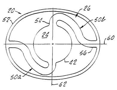
Fig. 3 illustrates the exemplary IOL 20 in plan view, wherein a generally
circular
periphery or peripheral edge 42 defines the radially outer extent of the optic
24 and
separates a posterior face from an anterior face. The optic 24 is typically
circular, but
may exhibit a different shape as long as the optical correction character is
centered about
the optical axis OA. The optic 24 may be bi-convex, or the anterior and
posterior faces
can take other shapes, such as planar or concave. In any event, the posterior
face and
anterior face are spaced apart on opposite sides of an optic plane (not shown)
that
WO 2005/027796 CA 02537906
2006-03-0310
PCT/US2004/029704
extends perpenchculanto the optical axis OA. In other words, the optic 24 is
centered on
and oriented in the optic plane.
In a prefertedenibodiment, the optic 24 is a multifocal optic having a
plurality of
zones of varying optical powers, wherein the maximum add power of the Anear
zones is
reduced by an amount equivalent to the diopter shift obtained through axial
movement
of the optic 24. Thus, the net power correction in the near zones is equal to
the patients
full add prescription only when optic 24 has moved to the near distance (i.e.
anteriormost) position. Examples of suitable multifocal optics are disclosed
in Lang et
al. U.S. Patent No. 6,231,603 and Lang et al. PCT International Application
No.
WO/01/82839 Al. The disclosures of both the U.S. patent and this PCT
international
application are incorporated in their entireties herein by reference.
The movement assembly 26 comprises a pair of intermediate members 50a, 50b
connected to and extending between the circular periphery 42 of the optic 24
and an
outer ring 52. Each intermediate member 50a, 50b has an inner end 54 connected
to the
circular periphery 42, and an outer end 56 connected to the outer ring 52.
AConnected
in this sense means firmly attached to with adhesive or ultrasonic bonding, or
preferably
formed integrally, or as a cohesive single piece. In the latter case, the lens
is desirably
molded. Each intermediate member 50a, 50b is desirably oriented in a plane
that is in
the optic plane. Indeed, the intermediate members 50a, 50b and outer ring 52
may have
approximately the same thickness and be located in the same plane.
Although controlled fibrosis (i.e., cellular growth) on the outer ring 52 may
be
desirable, the 10Ls 20 of the invention inhibit cell growth, particularly
epithelial cell
growth, onto the optic 24. This is accomplished by configuring the periphery
42 of the
optic 24 with mechanical barriers such as relatively sharp posterior and/or
anterior edge
comers. The proliferation of unwanted epithelial cell growth may also be
inhibited
through the use of material properties.
The intermediate members 50a, 50b of the IOL 20 are substantially longer than
previous intermediate members as they extend in a nonlinear fashion from the
outer ring
52 to the circular optic periphery 42. More particularly, the inner end 54 and
outer end
CA 02537906 2006-03-03
WO 2005/027796 11 PCT/US2004/029704
56 are angularly spaced about the optical axis OA by at least approximately 90
. The
mid-portion of each intermediate member 50 extends in a serpentine fashion
between its
inner and outer ends.
In a preferred embodiment, as Seen in Fig. 3, the outer ring 52 is oval in
shape
and'has a major axis 60 perpendicular to the optical axis OA. A minor axis 62
extends
perpendicularly to the major axis 60 and to the optical axis OA. DesirabW, the
outer
ends 56 of the intermediate members 50 connect to the oval ring 52 along the
majcir axis
60. In this way, the length of the intermediate members 50 is maximized. In
the
illustrated embodiment, the inner ends 54 of the intermediate members 50
connect to the
circular optic periphery 42 along the minor axis 62. Therefore, the inner and
titer ends
54, 56 are angularly spaced apart by about 90 .
Fig. 4 illustrates an alternative IOL 70 of the present invention having an
optic
72, an oval outer ring 74, and a pair of intermediate members 76a, 76b
extending
radially therebetween. Again, the optic 72, outer ring 74 and intermediate
members 76a,
76b are desirably formed as a single homogeneous (i.e., integral) piece. The
oval outer
ring 74 is believed to move the optic 72 axially with greater effectiveness
than a circular
ring because of the orientation of the intermediate members 76a,b along the
major axis.
The fixation members 76a,b are shown as plate-like, and desirably are greater
in
width (the dimension parallel to the minor axis) than axial thickness (the
dimension
parallel to the optical axis). Preferably, the ratio of width to axial
thickness is about
four. In absolute terms, the width of the fixation members 76a, 76b may be
between
about 0.8 mm and about 3.0 mm.
Fig. 5 illustrates a still further IOL 80 having an optic 82, an outer ring
84, and
three evenly arranged and radially oriented intermediate members 86a, 86b and
86c.
Because the intermediate members 86 are not symmetric about any plane through
the
optical axis OA, forces exerted by the surrounding capsular bag do not act in
opposition
to one another and thus are translated more effectively into axial movement of
the optic
82. The radial thickness tr of the outer ring 84 is indicated, and is
desirably in the range
of 0.2-0.6 mm. Moreover, the corners, or at least one corner, of the outer
peripheral
WO 2005/027796 CA
02537906 2006-03-0312
PCT/US2004/029704
edge of the outer ring 84 are desirably relatively sharp to reduce the
instance of epithelial
cell growth thereon. '
Figs. 6 and 6A illustrate a still further IOL 90 having an optic 92, a
plurality of
intermediate members 94 extending radially ()inward therefrom, and atl outer
ring 96.
The edge surface 97 of the outer ring 96 may be contoured to conform to the
inner wall
of the capsular bag. Therefore, as seen in Fig. 6A, at least a portion 98 of
the edge
surface 97 is convexly outwardly curved. At the same time, at least one
corner, in this
case the posterior corner 99, is left sharp (i.e. unpolished) to form a
barrier against
posterior capsular opacification (PCO).
Furthermore, Fig. 6 illustrates the greater axial thickness ta of the outer
ring 96
with respect to the axial thickness of the intermediate members 94 and optic
92.
Specifically, the axial thickness ta of the outer ring 96 is desirably between
about 0.4
mm and about 1.0 mm. Without wishing to limit the invention to any particular
theory
of operation, it is believed that a ring having an axial thickness in this
range will place
both the posterior and the anterior zonules of the eye under tension. Thus,
both sets of
zonules work in unison to change the diameter of the capsular bag in response
to action
of the ciliary muscle, resulting in axial movement of the optic. A thinner
ring would not
interact as effectively with both sets of zonules, and thus, in all
likelihood, would result
in less axial movement.
In addition, an outer ring 96 having increased axial thickness will increase
the
pressure on the sharp corner 99 of the edge surface 97 to increase the barrier
effect of the
ring against PCO.
Figs. 7A-7E show another IOL 100 of the present invention having a circular
outer capsular bag support ring 102, an inner optic 104, and a movement system
comprising a plurality of radially-oriented plate-like intermediate members
106
extending therebetween. Preferably, the optic 104, whether it be bi-convex or
otherwise,
is circumscribed by a circular rim 105 to which the fixation intermediate
members 106
are directly attached. The rim 105 desirably has a constant axial dimension
and helps to
reduce glare while not increasing incision size.
WO 2005/027796
CA 02537906 2006-03-0313
PCT/US2004/029704
, Movement systems other than that shown may be suitable, such as a more
solid
interface rather than discrete intermediate members. However, separated
intermediate.
members with voids therebetween and between the optic 104 and support ring 102
are
preferred. The support ring 102, inner optic 104, and intermediate members 106
are ,
firmly attached to each other with adhesive or ultrasonic bonding, or
preferably formed
integrally, i.e., molded or machined as one cohesive (homogeneous) piece Of
material.
The IOL 100 is desirably liquid injection molded from silicone or machined
from a
hydrophilic material which fabrication process reduces cost and increases
quality and/or
consistency of the product.
Fig. 7A illustrates the IOL 100 from the posterior side, while Fig. 7B is an
anterior view. These two views show the axial position at which the
intermediate
members 106 attach to the support ring 102. That is, the support ring 102 has
an axial
dimension and the intermediate members 106 attach to a posterior edge thereof.
When
implanted, the intermediate members 106 and connected optic 104 are therefore
held in
a posterior-most position with respect to the support ring 102.
As in the embodiment of Fig. 6, the edge surface of the outer ring 102 is
contoured to facilitate implantation within the capsular bag of the patient.
More
particularly, the support ring 102 has an outer surface that is convexly
curved to better
mate with the concave inner wall portion of the capsular bag between the
anterior and
posterior zonules.
With reference to Fig. 7C and 7E, the intermediate members 106 comprise a
radially inner portion 108, a radially outer portion 110, and a hinge 112
therebetween.
The inner and outer portions 108, 110 are generally plate-like having larger
circumferential dimensions then axial dimensions. The hinge 112 may be formed
in a
number of ways, and as illustrated comprises a region wherein both the axial
and the
circumferential thickness are reduced by about 50% with respect to the inner
and outer
portions 108, 110. The reduced material at the hinge 112 means that it is
weaker than
the remaining intermediate member and thus will more easily bend at that
location. The
location of each hinge 112 is desirably the same for all of the fixation
intermediate
CA 02537906 2006-03-03
WO 2005/027796 14 PCT/US2004/029704
members 106, and preferably is closer to the support ring 102 than to the
optic 104. For
example, each hinge 112 may be located about 60% of the way from the optic 104
to the
support ring 102...
Fig. 7D illustrates the IOL 100 in elevational view wherein the support ring
102
lies substantially in a plane and the optic 104 projects in a posterior
direction therefrom
by virtue of the shape of the intermediate members 106. Specifically, the
intermediate
members 1.06 are bowed slightly in the posterior direction such that the optic
104 will
tend to lie against or closely adjacent to the posterior wall of the capsular
bag. As
explained above, relaxation of the ciliary muscles surrounding the capsular
bag either
moves the optic 104 in the anterior direction or 'educes the posterior bias
imparted
thereto by the intermediate members 106. As a result, the vitreous humor
behind the
capsular bag can move the optic 106 forward, or in the anterior direction.
In one exemplary embodiment, the support ring 102 has a diameter of between
about 9.0-10.5 mm, and an axial thickness of about 0.7 mm. Furthermore, the
support
ring 102 has a curvature that mimics the curvature of the natural capsular bag
between
the anterior and posterior zonules, which curvature is between about 0.3-1.0
mm. As
mentioned above, at least one corner edge of the outer ring is left sharp to
help prevent
cell growth thereon.
Although three radial intermediate members 106 are illustrated 1201 apart, the
configuration of the intermediate members 106 may vary. However, two factors
that are
believed to facilitate axial movement, or accommodation, of the optic 104 are
the tripod
orientation and presence of the hinges 112. More specifically, inward radial
forces from
the surrounding ciliary muscle and intermediary zonules are transmitted from
the
support ring 102 through the intermediate members 106 to the optic 104.
Because the
intermediate members 106 are oriented so that none is diametrically opposed to
another,
there are no directly opposing forces and a larger component therefore
translates into
axial movement of the optic 104.
The intermediate members 106 are plate-like to increase stability of the lens
in
the eye. That is, the forces imparted by the surrounding ciliary muscle may
not be
WO 2005/027796 CA
02537906 2006-03-03 15
PCT/US2004/029704
entirely uniform and may exert torsional forces on the lens. Plate-like
intermediate
members 106 help resist twisting of the lens ,and thus increase stability. The
, circumferential thickness, or width, of the intermediate members 106
may be between
about 1.5-4.0 mm, and the axial thickness is desirably between about 0.2-0.5
mm.
Fig. 9 shows an alternate embodiment of an IOL 102' substantially similar to
the
embodiment of Figs. 7A-7E, except that the thickness of the hinge portion 112'
is
reduced in the axial direction only. That is, the circumferential thickness,
or width, of
each plate-like intermediate member 106' is uniform throughout its length.
This hinge
configuration has been found to be less susceptible to fibrosis than a hinge
configuration
having reduced thickness in the circumferential direction.
Another alternative IOL 120 of the present invention is seen in Figs. 8A-8D.
As
in an earlier embodiment, there are only two intermediate members 122
extending
between an oval shaped outer capsular bag support ring 124 and an inner
circular optic
126. In the illustrated embodiment, the outer ring 124 comprises a band having
a
generally, rectangular cross-section with a longer axial than radial
dimension.
Preferably, at least one corner of the outer ring 124 is sharp to prevent
epithelial cell
growth thereon. The support ring 124, inner optic 126, and intermediate
members 122
are firmly attached to each other with adhesive or ultrasonic bonding, or
preferably
formed integrally, i.e., molded or machined as a cohesive single piece. The
IOL 120 is
desirably liquid injection molded from silicone or machined from a hydrophilic
material
which, again, reduces cost and increases quality and/or consistency of the
product.
As seen best in Fig. 8D, the oval outer ring 124 has a major axis 121 and a
minor
axis 123, and the two intermediate members 122 are diametrically opposed
across the
optic 126 along the major axis 123. In one exemplary embodiment, the support
ring 124
has a major diameter of between about 115-135% of the minor diameter.
The intermediate members 122 are plate-like, each having a relatively larger
circumferential than axial dimension. In contrast to the IOL 100 of Figs. 7A-
7D, the
intermediate members 122 lie in a plane defined by the oval-shaped outer ring
124, and
thus the optic 126 is not bowed either way. Furthermore, the intermediate
members 122
WO 2005/027796 CA 02537906
2006-03-0316
PCT/US2004/029704
are joined to the inner surface of the outer ring 124 at approximately the
axial midpoint
thereof. Therefore, in'contrast to the earlier embodiment, the optic 126 is
not positioned
or biased to favor 'movement in one direction or the other.
With reference to Fig. 8A, each intermediate member 122 has a hinge 128
therein located closer to the outer ring 124 than to the optic 126. The
location of each
hinge 128 is desirably the same for all of the intermediate members 122, and
preferably
is located about 75% or more of the way from the. optic 126 to the support
ring 124.
Empirical determination of hinge 128 location optimizes the design such that
less radial
and axial compression force is required to axially translate the optic 126,
while at the
same time the ability of the lens to resist twisting is not adversely
affected. In the
illustrated embodiment, these hinges 128 are formed by reduced axial thickness
portions
along each intermediate member 122. For example, curved troughs on both sides
of
intermediate members 122 as shown may form the hinges. Alternatively, or in
addition,
the circumferential dimension of each intermediate member 122 may be reduced.
As with the earlier embodiment, the optic 126, whether it be biconvex or
otherwise, is recessed from a circular rim 130 to which the intermediate
members 122
are directly attached. The rim 130 is slightly tapered downward toward the
optic and
helps reduce glare on the lens. Desirably, the maximum axial dimension of the
rim 130
is greater than the center thickness of the optic 126. Advantageously, a
reduced center
thickness permits a reduction in incision size.
Figs. 10A-10C show an alternate embodiment of an IOL 120' similar to the
embodiment of Figs. 8A-8D, except that the optic 126' is multifocal, and oval
support
ring 124' has a non-uniform cross-sectional area. Specifically, the radial
thickness of the
support ring 124' increases from a minimum value to., for instance about 0.2
mm, at
diametrically opposed locations 125a and 125b along the minor axis 121', to a
= maximum value tr2 , for instance about 0.6 mm, at diametrically opposed
locations along
the major axis 123', where the intermediate members 122' are secured to the
ring 124'.
In addition, the axial thickness ta of the ring 124' is constant throughout
the entire
circumference of the ring 124' and has a value greater than the maximum radial
WO 2005/027796 CA 02537906
2006-03-0317
PCT/US2004/029704
thickness tr2.
The circumferential thickness, or width, of each intermediate member 122' is
also
non-uniform throughout its length, for instance decreasing in a non-linear
fashion from a
maximum width where the intermediate member 122' joins the circular rim 130'
of the
optiC 126' to a minimum width at the hinge 128', and remaining substantially
constant
between the hinge 128' and the outer ring 124'. This particular
configuration'of the oval
outer ring 124' and intermediate members 122' has been found to be
particularly stable,
with minimal "flopping", twisting, or other unwanted movement, of the thinnest
portions
125a and 125b of the ring 124'.
A series of tests were run on a prototype IOL in order to 'evaluate the
performance of the IOL under compression. The prototype IOL had the
configuration of
IOL 120' shown in Fig. 10 and was formed entirely of a unitary, reinforced
cross-linked
silicone polymeric material of the type described in Christ U.S. Patent Nos.
5,236,270,
5,376,694, 5,494,946, 5,661,195, 5,869,549, and 6,277,147. The disclosures of
each of
these U.S. patents are incorporated in their entirety herein by reference.
During the tests, it was observed that, when the IOL 120' was compressed an
amount in the range of about 0.3 min to about lmm, the image quality in the
far zone
132 improved slightly, while the image quality in the near zone (add power =
2D),
decreased slightly.
For isotropic compression or deformation a an equiconvex optic, there exists a
relationship between the amount of diametric compression (i.e. decrease in
refractive
zone size) and the increase in diopter power. With an increase in diopter
power, at least
some improvement in near vision can be expected. By combining the increased
diopter
power obtained through deformation of the optic 120' with that obtained
through axial
movement, it is believed that enhanced accommodation can be achieved. In other
words, a patients presbyopia can be effectively reduced. Still better
accommodation, or
further reduction of presbyopi a, can be obtained from the add power in the
near zone 134
of a multifocal optic 126', or from the maximum add power of an aspheric
optic.
Although the aforementioned tests were performed on an IOL 120' formed of a
WO 2005/027796 CA 02537906
2006-03-0318
PCT/US2004/029704
reinforced cross-linkefl *silicone polymeric material, the'ptinciples of the
invention will
apply equally well to accommodating '04 formed of any, ophthalmically
acceptable,
deformable material or combination of materials. For instance, one or more of
the optic
126', intermediate members 122', and outer ring 124' may be formed of an
acrylic
polymeric material. Particularly useful materials and combinations of
materials are
disclosed in patent application serial no. 10/314,069, filed December 5, 2002.
Furthermore, while each of the accommodation assemblies illustrated herein
comprises an outer ring surrounding and spaced frOm the optic with voids
therebetween,
and a plurality of intermediate members extending between and connecting the
optic and
the outer ring, these assemblies are merely exemplary. Other assembly
configurations
capable of effecting both axial movement and accommodating deformation of the
optic
are also included within the scope of the invention. For instance,
accommodation and/or
force transfer assemblies of the type shown in the aforementioned co-pending,
commonly assigned U.S. Patent Application Serial Nos. 09/656,661, 09/657,251,
and
09/657,325, may also be suitable.
While the present invention has been described with respect to various
specific
examples and embodiments, it is to be understood that the invention is not
limited
thereto and that it can be variously practiced within the scope of the
following claims.