Note: Descriptions are shown in the official language in which they were submitted.
CA 02538018 2006-03-06
WO 2005/029646 PCT/US2004/030537
BATTERY CABLE WITH PROVISIONS FOR INTEGRAL
CIRCUIT PROTECTION
BACKGROUND OF THE INVENTION
1. Field of the Invention
[0001] The present invention relates generally to a
battery cable circuit protection device and, more
particularly, to a battery cable with provisions for
integral circuit protection.
2. Description of the Background Art
[0002] Generally, a battery is mounted inside a vehicle
as a power source of electrical power, and electronic,
integrated circuits are designed to drive on voltage from
the battery and through the vehicle s electric system. As
used in this application, the term "vehicle" refers to any
motor vehicle including, but not limited to, a car, truck,
van, tractor trailer, bus, etc.
[0003] Electric system distribution lines may be affected
by sharp voltage fluctuations due to sharp changes in the
input current to components of the vehicle (e.g., air
conditioner, lights, windshield wipers, etc.). The
integrated circuits for the various electric loads may
suffer damage where overvoltages or undervoltages appear at
the power supply.
[0004] To obviate this problem, a prior approach consists
of using integrated circuits that can withstand such voltage
fluctuations. Consequently, the manufacture of these
circuit types (e.g., components and processing) is
expensive.
CA 02538018 2006-03-06
WO 2005/029646 PCT/US2004/030537
2
[0005] Another prior approach consists of connecting,
between the integrated circuit and ground, a device which
provides protection against the voltage fluctuations. One
such prior art system is disclosed in U.S. Patent No.
5,645,448 to Hill. As illustrated in Figure 1, a battery
connecting module 10 provides for electrical interconnection
between a battery 70, an alternator cable 74 connected to an
alternator (not shown), a starter cable 76 connected to a
starter motor (not shown), and a fuse box cable 78 connected
to a fuse box (not shown). A main fuse 80 can be
electrically connected between the alternator cable 74 and
the distributed electrical systems of the vehicle. Such
system, however, also aggravates the manufacturing costs as
well as add to the cost of assembling the electric system to
a vehicle (e. g., costs of additional parts).
[0006] Thus, there exists a need in the art for a power
conditioning between the main power source and electrical
devices to either eliminate and/or to adequately control
undesired power conditions.
SUNE2ARY OF THE INVENTION
[0007] The present invention solves the existing need by
providing a battery cable with provisions for integral
circuit protection, which has structural and performance
characteristics as to adequately guard from voltage
fluctuations in the battery supply.
[0008] According to one preferred embodiment of the
present invention, a battery cable circuit protection device
for preventing fluctuations in voltage from a supply battery
is provided. The device includes a terminal base having a
battery cable lug member adapted for mounting to and making
an electrical connection with a battery post of the battery.
CA 02538018 2006-03-06
WO 2005/029646 PCT/US2004/030537
3
A battery cable mounting structure is fixedly connected to
the terminal base for detachably connecting the terminal
base to a battery cable. The battery cable supplies a
vehicle starter motor with electrical energy. A first fuse
mount supported by the terminal base provides electrical
interconnection to the battery post. A second fuse mount
supported by the terminal base provides electrical energy to
vehicle electrical systems other than the vehicle starter
motor. The first and second fuse mounts are adapted for
detachable connection to a fuse which provides electrical
interconnection between the first and second fuse mounts.
[0009] According to another embodiment of the present
intention, a circuit for preventing fluctuations in voltage
from a supply battery comprising the battery cable circuit
protection device of the present invention a.s provided.
BRIEF DESCRIPTION OF THE DRAV~TINGS
[0010] The accompanying drawings, which are incorporated
herein and form part of the specification, illustrate
various embodiments of the present invention and, together
with the description, further serve to explain the
principles of the invention and to enable a person skilled
in the pertinent art to make and use the invention. In the
drawings, like reference numbers indicate identical or
functionally similar elements, and no discussion will be
given. A more complete appreciation of the invention and
many of the attendant advantages thereof will be readily
obtained as the same becomes better understood by reference
to the following detailed description when considered in
connection with the accompanying drawings, wherein:
CA 02538018 2006-03-06
WO 2005/029646 PCT/US2004/030537
4
[0011] FIGS. 1A and 1B are plan views of a battery cable
circuit protection device according to an exemplary
embodiment of the present invention;
[0012] FIG. 1C illustrates the battery cable circuit
protection device according to an exemplary embodiment of
the present invention being mounted on a battery;
[0013] FIG. 2 is the interior surface of the fuse cover
of the battery cable circuit protection device according to
the present invention;
[0014] FIGS. 3A and 3B are plan views of a battery cable
circuit protection device according to another embodiment of
the present invention;
[0015] FIG. 3C illustrates the battery cable circuit
protection device according to another embodiment of the
present invention being mounted on a battery; and
[0016] FIGS. 4A and 4B are schematic circuit diagrams of
the battery cable circuit protection device according to the
present invention in exemplary G7.rCU7.t configurations.
DETAILED DESCRIPTION OF THE PREFERRED EN,BODIMENTS
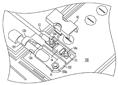
[0017] FIGS. 1A and 1B are plan views of a battery cable
circuit protection device according to an exemplary
embodiment of the present invention. Referring to FIGS. 1A
and 1B, the battery cable circuit protection device 10
comprises a terminal base 12, a high-current main fuse 14,
and a fuse cover 16. The battery cable circuit protection
device 10 of the exemplary embodiment adequately protects
the battery supply from voltage fluctuations (e. g.,
overvoltages or undervoltages).
[0018] The terminal base 12 has a battery cable lug or
post 102 preferably adapted for mounting to a studded
battery post 100a of a battery 100, as illustrated in FIG.
CA 02538018 2006-03-06
WO 2005/029646 PCT/US2004/030537
1C. FIG. 1C shows the battery cable circuit protection
device 10 being mounted on the battery 100. It will be
appreciated by those skilled in the art that the battery
cable post 102 can also be mounted to other battery
5 terminals, such as a SAE taper post battery terminal, etc.
The battery post 100a is secured to the battery cable post
102 via a nut 11.
[0019] The terminal base 12 also has battery mounting
legs 12a, 12b for securing a battery cable 101 (FIG. 1C) of
the battery 100. The battery mounting legs 12a, 12b prevent
torsional twisting and loosening of the battery cable 101.
The battery cable post 102 and the battery mounting legs
12a, 12b provide electrical interconnection between the
battery 100 and a starter motor (not shown). For example,
the starter cable connected to the starter motor can be
secured to the battery cable post 102.
[0020] The battery cable 101 can be attached through the
battery mounting legs 12a, 12b of the terminal base 12
without the use of tools. For example, if the terminal base
12 is slightly rotated (i.e., counterclockwise), the battery
cable 101 can be easily inserted through the battery
mounting legs 12a, 12b. The terminal base 12 should be
rotated back to the same plane as the battery cable 101
(i.e., clockwise).
[0021] Further, the terminal base 12 has a pair of
threaded studs 14a for accommodating the main fuse 14. The
main fuse 14 can be secured to the terminal base 12 via nuts
13 (FIG. 1C). The fuse 14 is the main feed and supplies all
the electrical energy to the electrical systems/components
of a vehicle. For example, the alternator cable connected
to an alternator (not shown) can be placed over a threaded
stud 14a in addition to the main fuse 14, and secured by a
CA 02538018 2006-03-06
WO 2005/029646 PCT/US2004/030537
6
nut 13. The main fuse 14 a.s enclosed by a fuse cover 16.
Preferably, the fuse cover 16 can be snapped onto the
terminal base 12.
[0022] The fuse cover 16 may have a spare fuse 22
detachably affixed to the interior surface 16a of the fuse
cover 16 by friction fit or other means, as illustrated in
FIG. 2.
[0023] The main fuse 14 provides a master circuit
protector for providing recharging protection by protecting
in the event of overtemperature conditions, providing
discharging protection by protecting in the event of
overcurrenb conditions, etc.
[0024] In the present invention, the battery to starter
cable remains attached to the battery cable post 102 and has
no intermediary straps or connections. The main fuse 14 and
the battery cable 101 both mount to the true battery stud
100a of the battery 100, using only the hardware supplied
with the standard battery cable to secure both elements.
Accordingly, any additional voltage drop in the
starting/cranking circuit is eliminated.
[0025]. FIGS. 3A and 3B are plan views of a battery cable
circuit protection device according to another embodiment of
the present invention, arid FIG. 3C illustrates the battery
cable circuit protection device being mounted on a battery.
Referring to FIGS. 3A-3C, the battery cable circuit
protection device 30 comprises a terminal base 32, a high-
current main fuse 14, and a fuse cover 36.
[0026] The terminal base 32 includes an elongated plate
300 having a battery cable lug or post 102 disposed at the
end portion of the plate 300. The elongated plate 300
further includes a connecting plate 300a that is affixed to
the terminal base 32 via a threaded stud 304 and a nut 306.
CA 02538018 2006-03-06
WO 2005/029646 PCT/US2004/030537
7
A second connecting plate 34 is mounted to the battery
cable circuit protection device 30 via a threaded stud 35
and a nut 38. The second connecting plate 34 can be
connected to other electrical systems/components via
threaded stud 39.
(0027] Similar to the embodiment illustrated in FIGS. 1A-
1C, a cover 36 encloses the main fuse l8. Although not
shown in the drawings for convenience, the fuse 18 is
disposed underneath the cover 36. A secondary spare fuse
can also be affixed to the interior surface of the fuse
cover 36.
[0028] FIGS. 4A and 4B are schematic circuit diagrams of
the battery cable circuit protection,device according to the
present invention in exemplary circuit configurations. FIG.
4A shows three batteries 401 in a box, and FIG. 4B shows
four batteries 401 in two boxes (e.g., two batteries par
box). Referring to FIGS. 4A and 4B, battery cables of the
batteries 401 are in parallel with the main fuse or circuit
breaker 14. The batteries 401 are the primary source and
supplies electrical energy only to the starter motor 405.
The starter motor 405 starts (via a starter relay 407), for
example, the ignition via ignition switch 402, provides
power to cab 404, EPDM 406, etc.
[0029] The circuit breaker 14 is the main feed and
supplies electrical energy to the other electrical
systems/components of the vehicle, such as, for example, an
alternator 409. Each electrical system is grounded 411 to
prevent electrical shock. The circuit breaker 14 further
provides a master circuit protector.
(0030] The battery cable circuit protection device of the
present invention has a major advantage in that it protects
against possible overvoltages (and undervoltages) in the
CA 02538018 2006-03-06
WO 2005/029646 PCT/US2004/030537
8
supply from the battery to which it is connected, in
addition to protecting the electric loads driven by it.
Further, the battery cable circuit protection device of the
present invention is structurally quite simple and
implementable as an integrated circuit for a low
manufacturing~cost.
[0031] The foregoing has described the principles,
embodiments, and modes of operation of the present
invention. However, the invention should not be construed
as being limited to the particular embodiments described
above, as they should be regarded as being illustrative and
not as restrictive. It should be appreciated that
variations may be made in those embodiments by those skilled
in the art without departing from the scope of the present
invention.
[0032] While a preferred embodiment of the present
invention has been described above, it should be understood
that it has bean presented by way of example only, and not
limitation. Thus, the breadth and scope of the present
invention should not be limited by the above described
exemplary embodiment.
[0033] Obviously, numerous modifications and variations
of the present invention are possible in light of the above
teachings. It ,is therefore to be understood that the
invention may be practiced otherwise than as specifically
described herein.