Note: Descriptions are shown in the official language in which they were submitted.
CA 02538940 2006-03-03
BANDAGE WITH SENSORS
BACKGROUND OF THE INVENTION
[0001] Core body temperature is an important indicator of a person's health.
Traditionally non-
invasive measurement of body temperature is based on oral, rectal, tympanic
(ear), or axial
(armpit) thermometers. Typically these provide a single temperature
measurement per use and
are not used to provide long-term monitoring of a patient's temperature. More
recently, clinical
thermometers based on the measurement of skin temperature over the superficial
temporal
artery of the forehead have appeared. The current implementations of these
thermometers are as
hand-held wands that are manually scanned across the forehead region. For long
term
monitoring of body temperature a thermometer that is unobtrusive and can be
left affixed to a
patient is needed.
[0002] Temporal Artery Thermometers (TAT), as disclosed in U.S. Patent
Numbers:
6,292,685; 6,499,877 B2; 6,932,775 B2, provide a non-invasive means of
measuring a person's
core body temperature by scanning a hand-held device with an integrated
infrared temperature
sensor across the superficial temporal artery on the forehead. The devices
described in the
above disclosures all use an infrared imager for the temperature sensor. This
sensor must then
be manually scanned across the forehead in order to obtain a temperature
reading. As such
these devices are not suited for long term monitoring of patient temperature.
The methods
disclosed all rely on estimating the core temperature using both a skin
temperature
measurement and the ambient temperature. For a bandage based thermometer, the
ambient
temperature may be a poor indicator of the local conditions at the bandage
site (for example, if
the patient's head in on a pillow), therefore the use of ambient temperature
can lead to
inaccurate core temperature estimates.
[0003] U.S. Patent Number 6,646,567 discloses a body temperature measurement
system
which provides a wireless link between the on-body temperature sensing device
and a remote
receiver. The device described uses a temperature probe in contact with the
body whose
temperature is to be measured. Since skin temperature alone is not a good
indicator of core
CA 02538940 2006-03-03
2
temperature, such a temperature measurement method fails to provide an
accurate measurement
of core body temperature when used in a bandage based temperature sensor
application.
[0004] U.S. Patent Number 6,416,471 discloses a health parameter measurement
system which
comprises an on-body sensor band for measurement of the requisite health
parameters, a
wireless transmission link between the sensor band and a second on-body (or in
close
proximity) transceiver which retransmits the health parameter data over a
second wireless link
(or by a telecommunications link) to a remote monitoring station. This
disclosure describes a
system for wirelessly transmitting health parameter data but not the specifics
of gathering that
data.
[0005] U.S. Patent Number 6,929,611 discloses a head mounted body temperature
measurement device, where the temperature sensor is held by a strap onto
either the center of
the forehead or the fontanel of an infant. This disclosure describes a method
of estimating core
temperature based on a single skin temperature measurement and a second
environment
temperature. The temperature sensor, however, is placed in the center of the
forehead, which is
not the optimal placement for estimating the core temperature. The temperature
sensor is held
in place using a strap or helmet, a much less comfortable method than a
bandage.
[0006] U.S. Patent Number 6,890,096 discloses a body temperature measuring
device that uses
a single skin temperature measurement along with a heat flux sensor to
estimate body
temperature. The disclosed method is focused on reducing the time needed until
a valid
temperature reading is obtained once the temperature probe comes in contact
with the skin.
Since the bandage based thermometer is in-place for long periods of time,
thermal equilibrium
is reached soon after the initial attachment and thereafter no special
techniques are needed to
improve temporal response.
SUMMARY OF THE INVENTION
[0007] The described invention improves upon the prior state of the art in
several ways. In one
aspect of the invention, a device is provided to estimate the core body
temperature based on
multiple temperature measurements made in the temple region of the forehead
without the need
CA 02538940 2006-03-03
3
to manually scan the temperature sensor across this region. The core
temperature may be
estimated using only temperatures measured locally to the bandage. There is no
need for an
ambient temperature reading, thereby eliminating errors related to variation
in heat flow out of
the forehead due to specific environmental conditions of the space surrounding
the forehead
region. The temperature sensing device may be affixed to the forehead region
as a small
flexible bandage, eliminating the need for cumbersome straps or helmets. Only
raw sensor data
need be transmitted to the remote receiver, thereby minimizing the sensor
module's power
consumption.
[0008] According to one aspect of the invention, the device can be used for
other
measurements, and therefore there is also provided a measuring device,
comprising: a bandage;
an array of sensors attached to the bandage, the sensors of the array of
sensors having exposed
sensing surfaces; and the sensors of the array of sensors having an output.
[0009] According to a further aspect of the invention, there is provided a non-
invasive means
of estimating core body temperature using a mufti-sensor thermometer that is
constructed in a
flexible bandage like form and affixed to the temple region of a patient's
forehead.
[0010] In a further aspect of the invention, there is provided a system for
measurement of core
body temperature which consists of two parts: a device that is affixed to the
forehead in the
region of the temple, and a device to receive and process the sensor data
transmitted wirelessly
by the device affixed to the forehead.
(0011] According to an aspect of the invention, the device affixed to the
temple region of the
forehead is provided as a flexible bandage. The bandage includes two arrays of
temperature
sensors. The first array of temperature sensors is positioned on the bottom
surface of the
bandage and provides a set of measurements of temperature of the skin that is
underneath each
sensor. The second temperature sensor array is positioned towards the outer
surface (away from
the skin) of the bandage and is separated from the first temperature array by
a layer of
thermally insulating material. An electronic circuit is used to measure the
output of each
temperature sensor in each array. The sensor readings are then transmitted by
wireless means to
CA 02538940 2006-03-03
4
a remote receiver. A processor in the receiver converts the sensor readings
into an equivalent
temperature reading if this conversion is necessary and has not already been
performed prior to
the transmission of the data. The processor then chooses the sensor reading
from the skin
temperature sensing array which represents the highest skin temperature. For
convenience, this
reading will be designated as Tsk;". The processor then chooses the sensor
reading from the
outer temperature sensor array which is in closest physical proximity to the
sensor that
provided Tsk",, for convenience, this sensor reading is designated To"te~. The
processor then
estimates the core body temperature using the formula
ore = ~ki,i + a(T khi - Tourer ) ( 1.1 )
where a represents an empirically determined parameter the value of which will
depend on the
thermal properties of the bandage.
[0012] For those skilled in the art, it is clear that the conversion of
temperature sensor array
measurements to an estimated core body temperature reading could equally well
be performed
in the device affixed to the forehead, in which case only the core temperature
reading need be
transmitted to the receiver. Equally, part of the conversion process could be
performed in the
device affixed to the forehead, and partially in the receiver.
[00I3] The receiver can display the body temperature directly, as well as
sending the
information to other systems used to monitor and record patient medical
information.
BRIEF DESCRIPTION OF THE DRAWINGS
[0014] There will now be described preferred embodiments of the invention, by
reference to
the figures by way of example, in which like numerals denote like elements,
and in which:
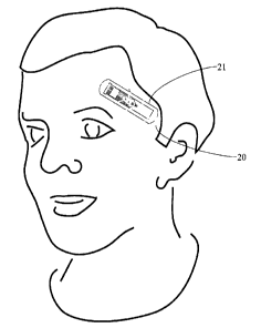
[0015] Figure 1 shows a bandage thermometer positioned on the forehead in the
temple region.
[0016] Figure 2 shows a bandage thermometer positioned on the forehead in the
temple region
along with the remote receiver.
[0017] Figure 3 shows an exploded view of one embodiment of the bandage
thermometer.
[0018] Figure 4 shows an exploded view of the cross-sectional view of one
embodiment of the
bandage thermometer.
[0019] Figure 5 shows a cross-sectional view of one embodiment of the bandage
thermometer.
CA 02538940 2006-03-03
(0020] Figure 6 shows a bottom view of one embodiment of the bandage
thermometer.
[0021] Figure 7 shows one of the temperature sensor elements.
DETAILED DESCRIPTION OF PREFERRED EMBODIMENTS OF THE INVENTION
[0022] In the claims, the word "comprising" is used in its inclusive sense and
does not exclude
other elements being present. The indefinite article "a" before a claim
feature does not exclude
more than one of the feature being present.
[0023] The bandage thermometer 21 is affixed to the forehead in the temple
region. In this
position, the bandage should overlay a portion of the superficial temporal
artery 20 that lies just
beneath the skin surface in this region. The bandage can be equally affixed to
either the left or
right temple region of a patient's forehead.
[0024] In order to estimate the core body temperature, the temperature of the
skin (Tsk;n), which
is preferably overlying a portion of the superficial temporal artery, is
measured along with a
second temperature (Tourer) that is used to subsequently estimate the heat
flowing out of the skin
in this region. By combining the two temperatures, the core body temperature
can be estimated
using:
Tcore = Tckin + a (Tckbt - Tourer ) ( I .2)
where Tsk~n preferably represents the temperature of the skin in a region in
close proximity to
the superficial temporal artery, Tourer the temperature of the outer
temperature sensor which is in
closest proximity to the skin temperature sensor which provided the Tskin
measurement. The
parameter, a, is an empirically determined coefficient which depends upon the
physical
construction and thermal characteristics of the bandage, and the physical
location of the
temporal artery relative to the bandage and the thermal characteristic of the
tissue separating
the artery from the temperature sensor. The physical and thermal
characteristics of the bandage
can be well controlled by its construction. The location of the artery and
thermal characteristics
of the overlying tissue will vary with each individual and with each
particular placement of the
bandage. Therefore a is best determined through the use of clinical trials
using a specific
implementation of the bandage.
CA 02538940 2006-03-03
6
(0025] In the preferred embodiment, multiple temperature sensors 8 are arrayed
longitudinally
along the bottom surface (the surface facing towards the skin) of the bandage.
Although this
specific embodiment shows an array of five sensors, a different number of
sensors could be
used. The trade-off is accuracy versus cost. Fewer sensors means that average
distance between
the temporal artery and the closest sensor will be increased, therefore
reducing the accuracy of
the body temperature estimation. More sensors increase cost. The sensors 8 are
spaced
approximately 10 mm apart. To extend the physical region of temperature
sensing, each
temperature sensor 30 is embedded within a disk 31 of material approximately 5
mm in
diameter which possesses a high thermal conductivity. A flexible printed
circuit board, is used
to mount the sensors as well as to provide electrical connectivity between the
sensors and the
processor module 9. For clarity the flexible printed circuit board is shown in
most figures as
consisting of an upper 5 and lower 2 parts, but is constructed as a single
unit which is then
folded over. The processor module 9 contains the electronic circuitry
necessary to provide a
means of measuring the outputs of the temperature sensors, processing that
information as
necessary, and transmitting it by wireless 23 means to the remote receiver 22.
Although shown
in the diagrams as a single entity, the processor module 9 represents the
grouping of individual
components necessary to implement the sensor interface, data processing, and
the wireless link.
A thin layer of flexible material 1 is attached to the bottom surface of the
flexible printed
circuit board 2, and contains holes 7 through which the sensor elements
protrude. The skin side
of the material is covered with an adhesive which allows the bandage to be
temporarily affixed
to the skin. The combination of the slight protrusion of the sensor elements
thorough the
insulating layer, the use of the thermal conductive disk 31 to increase the
surface area of the
temperature sensor 30, and the adhesive properties of the bottom surface of
the bandage helps
ensure that the skin temperature sensors make good thermal contact with the
skin, and therefore
can provide an accurate measurement of the underlying skin temperature.
[0026] A second temperature sensor array 10, of similar construction to the
skin temperature
sensor array 8, is arranged towards the outer (away from the skin) surface of
the bandage. In
the preferred embodiment, the outer temperature sensor array is positioned
such that the
individual sensor elements of the second array 10 approximately overlay the
corresponding
CA 02538940 2006-03-03
7
sensor elements in the first array 8, but are separated from the first array
elements by an
intervening layer of material composed of two layers 3 and 4 for ease of
construction. This
intervening layer would typically be composed of insulating material so that a
reasonable
temperature difference can be measured between the first and second
temperature array sensors
under normal ambient conditions.
[0027] The second temperature sensor array 10 is attached to the same flexible
printed circuit
board 5 and 2 as the first array 8. The flexible printed circuit board is
folded over so that the
sensor elements of the first and second array are aligned with each other. A
composition of
insulating material is sandwiched between the two sensor arrays. This
composition consists of
two layers for ease of construction. The bottom layer 3 contains a hole to
allow the folded
flexible printed circuit board to pass through, and possibly a second cavity
15 to provide
enough room for the processor module 9 to fit. The bottom layer ensures that
the second array
of sensor elements are separated from the first sensor array by a layer with
well-controlled
thermal properties. The upper layer 4 contains holes 14 for both the flexible
printed circuit
board and the processor 16, along with holes L l for each of the temperature
sensor elements of
the second sensor array 10. The flexible printed circuit board also provides
the electrical
connectivity 12 between the sensor arrays 8 and 10 and the processor module 9
and any other
components such as the battery and the antenna used for the wireless link. The
components
processor module also mounted on the flexible printed circuit board.
[0028] The two temperature sensor arrays 8 and 10 plus the intervening
material 3 and 4 allow
the heat flow through the bandage to be to be estimated. It is this heat flow
estimate that allows
the core body temperature, as indicated by the temperature of the blood within
the temporal
artery, to be estimated from the skin temperature measurement. In most of the
prior art, the heat
flow out of the skin is estimated by measuring the ambient temperature of the
surrounding
environment. This provides a much less accurate estimate of the heat flow and
one prone to
error due to variation in the local environment immediately surround the site
at which the skin
temperature measurement is made.
CA 02538940 2006-03-03
8
[0029] 1n order to obtain the best estimate of the core body temperature, the
skin temperature
sensor with the highest temperature reading is chosen to represent the skin
temperature Tsk;"
since this should correspond to the location where the sensor is in closest
proximity to the
temporal artery. Once the appropriate skin temperature sensor has been
selected, the outer
temperature To"~r can be measured from the temperature sensor in the second
temperature array
which is in closest physical proximity to the selected skin temperature
sensor. The heat flowing
out of the skin can now be estimated using
qbandage - hmateria! (Tskin - Tnuter ) ( 1 .3 )
where hm~eri~ is the thermal coefficient of conductivity of the material
between the two
temperature sensors, including that of the flexible printed circuit board 2
and that of the thermal
insulating material layer 3 and 4.
[0030] Once the heat flow out of the skin is known, the heat balance equation
can be solved to
estimate the temperature of the underlying artery and hence the core body
temperature. The
heat balance law states that the heat flowing out of the body must equal the
heat lost through
the bandage, or
fna~~ - hrissue (T~a,~e - Ts~n ) ( 1.4)
Combining equations (1.3) and (1.4) leads to the heat balance equation
htiesue (Tcare - Trkiu ) - hmaterial (Tskiu - Tauter ) ( 1 .5 )
which reduces to the equation for core temperature (1.1) if
a - ''material . ( 1 .6)
htissue
[0031] The thermal conductivity coefficient hmater~a~ Can be measured
experimentally and
depends on the particular bandage construction and the material used. The
tissue coefficient
hmater~ai can be estimated from generally known thermal coefficients of tissue
and an estimate of
the average artery location. Alternately, the overall coefficient a can be
determined
experimentally using clinical trials, which is the preferred method.
CA 02538940 2006-03-03
9
[0032) Once the core body temperature is estimated, it is transmitted by
wireless means to a
remote receiver for monitoring.
[0033] In an alternate embodiment, the processor module 9 on the bandage would
simple
collect the raw sensor measurements and transmit that data to the remote
receiver 22. At the
remote receiver, the raw data would be converted into a core body temperature
estimate. By
preforming the majority of the data in the receiver, the power consumption of
the processor on
the bandage can be reduced and more sophisticated processing of the data can
be implemented
(error screening, averaging, etc.).
[0034) In yet another embodiment, the processing of the raw sensor data can be
distributed
between the bandage and the remote receiver. This allows the overall power of
the bandage to
be minimized by optimizing the power consumed by data processing versus power
consumed
by the wireless link. The more data processing is performed on the bandage the
fewer bytes of
data need to be transmitted. The optimum split between in the processing
performed on the
bandage versus the receiver will depend on the characteristics of the specific
implementation of
the processor module and the wireless transmission scheme used.
[0035) In order to minimize power consumption of the electronic circuitry
located on the
bandage, it may be desirable to transmit by wireless means all of the raw
temperature sensor
measurements to the remote receiver. The selection of the maximum skin
temperature and
corresponding outer temperature and subsequent calculation of the core
temperature can then
be performed by the processor at the receiver. Since the receiver can be line
powered, power
consumption is not a concern.
[0036] The remote receiver can have a means of entering a patient's core body
temperature that
was measured by some alternate means. The processor used to calculate the core
body
temperature can then use the alternately measured body temperature to adjust
the coefficient, a,
in order to calibrate a particular bandage to the specific patient. If the
calculation of the core
body temperature is performed on the bandage, a bidirectional wireless link 23
and 24 can be
CA 02538940 2006-03-03
used to upload the new value of a to the bandage, where it can be Stored in
some form of non-
volatile memory.
[0037] An array may have any shape, and may be linear, two dimensional or
three dimensional.
The inner array establishes a baseline. The outer array may have the same or a
different shape
as compared with the first array. Preferably, the baseline is the skin
temperature, and for this it
is preferred that the sensors be in thermal contact with the skin. The
intervening material
between the two arrays can be any suitable material or materials and may
comprise several
layers. A processor may include a transmitter and receiver. The bandage can be
any shape.
[0038] Immaterial modifications may be made to the embodiments of the
invention described
here without departing from the invention.