Note: Descriptions are shown in the official language in which they were submitted.
CA 02547204 2006-05-25
WO 2005/055117 PCT/CA2004/002062
INTER-PROCESSOR PARAMETER MANAGEMENT IN A MULTIPLE-PROCESSOR
WIRELESS MOBILE COMMUNICATION DEVICE OPERATING ON A PROCESSOR
SPECIFIC COMMUNICATION NETWORK
CROSSREFERENCE TO RELATED APPLICATION
[0001] The present application claims priority from US Provisional Patent
Application No.
60/526,322, filed December 2, 2003, the complete drawings and specification of
which are
incorporated herein by reference
BACKGROUND
to TECHNICAL FIELD
[0002] This application relates to mobile communication techniques in general,
and inter-
processor parameter management in a multiple-processor wireless mobile
communication
device operating on a processor specific communication network in particular.
DESCRIPTION OF THE RELATED ART
[0003] In wireless mobile communication devices, referred to herein primarily
as "mobile
devices", a single processor typically handles all device functionality,
including device
software applications, data processing, and communication functions, for
example.
However, in order to operate on some modern wireless communication networks, a
mobile
device must include a particular processor or type of processor. For example,
the iDENT"'
communication network developed by Motorola is one such network that requires
a particular
mobile device processor.
[0004] This network specific processor requirement may be met for new mobile
devices by
developing operating system software and software applications targeted to the
network
specific required processor. For existing mobile devices for which operating
systems and
software applications have already been developed based on a different mobile
application
1
CA 02547204 2006-05-25
WO 2005/055117 PCT/CA2004/002062
specific processor however, providing for mobile device operation on such a
network while
maintaining mobile device functionality can be much more challenging,
particularly when
proprietary technologies are embodied in both the network specific processor
and the mobile
application specific processor. One such mobile device functionality that is
challenging to
maintain is battery charging and battery management.
SUMMARY
[0005] According to one aspect of the present application, there is provided a
system of
enabling auxiliary functions in a mobile device operable in a wireless
network, the system
comprising: a first data processor configured to ~be operable with at least
one mobile device
to application; a second data processor of a preselected data processor type
required for
operation with the wireless network, configured to manage wireless
communication
operations with respect to the wireless network for the mobile device; at
least one auxiliary
function configured to be operable with one of the first data processor and
the second data
processor; and a data communication channel between the first data processor
and the
second data processor, wherein data that is received by or to be sent from the
mobile device
through the wireless network is exchanged between the first data processor and
the second
data processor through the data communication channel, and wherein at least
one message
is sent by one of the first data processor and the second data processor to
the other of the
first data processor and the second data processor through the data
communication channel
2o to enable the at least one auxiliary function of the mobile device for one
of the first data
processor and the second data processor.
[0006] Other aspects and features of the present application will become
apparent to those
ordinarily skilled in the art upon review of the following description of
specific embodiments of
inter-processor function control through parameter management in a multiple-
processor
wireless mobile communication device operating on a processor specific
communication
network in conjunction with the accompanying figures.
2
CA 02547204 2006-05-25
WO 2005/055117 PCT/CA2004/002062
BRIEF DESCRIPTION OF THE DRAWINGS
[0007] Embodiments of the present application will now be described, by way of
example
only, with reference to the attached figures, wherein:
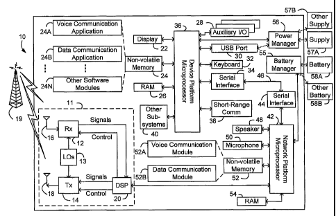
FIG. 1 is a block diagram of a multiple-processor mobile device;
FIG. 2 shows battery voltage thresholds that can trigger battery management
and
charge management messaging in accordance with the techniques of the present
application, in an exemplary multiple-processor mobile device;
FIG. 3 shows messages exchanged between first and second data processors in
accordance with the techniques of the present application in an exemplary
multiple-
1o processor mobile device;
FIGS. 4-7 are block diagrams depicting system-level components of a multiple-
processor mobile device provided in accordance with the techniques of the
present
application.
[0008] Same reference numerals are used in different figures to denote similar
elements.
DETAILED DESCRIPTION OF THE DRAWINGS
[0009] FIG. 1 is a block diagram of a multiple-processor mobile device 10. The
mobile
device 10 shown in FIG. 1 is a dual-mode device having both data and voice
communication
functions. However, it should be appreciated that many implementations may be
used, such
as but not limited to voice-only, data-only or possibly other types of
multiple-mode devices,
2o including, for example, cellular telephones, PDAs enabled for wireless
communications, one-
way and two-way pagers, wireless email devices and wireless modems. The mobile
device
10 includes a transceiver 11, a first microprocessor 36, and a second
microprocessor 42, as
well as components associated with each microprocessor. These components
include a
display 22, a non-volatile memory 24, a RAM 26, auxiliary input/output (I/O)
devices 28, a
universal serial bus (USB) port 30, a keyboard 32, a serial interface 34, and
a short-range
communications subsystem 38 associated with the first microprocessor 36, as
well as a
serial interface 44, a speaker 48, a microphone 50, a non-volatile memory 52
and a RAM 54
associated with the second microprocessor 42. Such a device also typically
includes other
3
CA 02547204 2006-05-25
WO 2005/055117 PCT/CA2004/002062
device subsystems shown generally at 40. Although the other device subsystems
40 are
shown as being associated with the first microprocessor 36, these subsystems
may be
associated with either, or possibly both, of the microprocessors 36, 42.
[0010] Ln order to meet the network specific processor requirement without
having to
sacrifice mobile application specific functionality at least two processors
are used in the
multiple-processor mobile device 10: the network specific processor or network
platform
processor 42 and the mobile application specific processor or device platform
processor 36,
which co-operate via some form of inter-processor communication such as via
serial
interfaces 34 and 44. Thus, mobile device manufacturers can maintain their
operating
1o systems and software applications on the mobile application specific
processor, while
meeting the network specific processor requirement.
[0011] The mobile device 10 is preferably a two-way communication device
having voice
and data communication capabilities. Thus, for example, the mobile device 10
may
communicate over a voice network, such as any of the analog or digital
cellular networks,
and may also or 'instead communicate over a data network. The voice and data
networks
are depicted in FIG. 1 by the communication tower 19. These voice and data
networks may
be separate communication networks using separate infrastructure, such as base
stations,
network controllers, etc., or they may be integrated into a single wireless
network.
[0012] The communication subsystem 11 is used to communicate with the wireless
network
19, and includes a receiver (Rx) 12, a transmitter (Tx) 14, one or more local
oscillators (LOs)
13, and a digital signal processor (DSP) 20. The DSP 20 sends communication
signals to
the transmitter 14 and receives communication signals from the receiver 12. In
addition to
processing communication signals, the DSP 20 provides appropriate control of
receiver 12
and transmitter 14 using various algorithms and control signals. For example,
the gain levels
applied to communication signals in the receiver 12 and transmitter 14 may be
adaptively
controlled through automatic gain control algorithms implemented in the DSP
20. Other
transceiver control algorithms could also be implemented in the DSP 20 in
order to provide
more sophisticated control of the transceiver 11. Although DSP 20 is shown as
part of
4
CA 02547204 2006-05-25
WO 2005/055117 PCT/CA2004/002062
transceiver 11, DSP 20 may be alternatively located in the network platform
microprocessor
42.
[0013] If device communications through the wireless network 19 occur at a
single
frequency or a closely-spaced set of frequencies, then a single local
oscillator 13 may be
used in conjunction with the transmitter 14 and receiver 12. Alternatively, if
different
frequencies are utilized for voice communications versus data communications
or
transmission versus reception, then a plurality of local oscillators 13 can be
used to generate
a plurality of corresponding frequencies. Although two antennas 16 and 18 are
depicted in
FIG. 1, the mobile device 10 could be used with a single antenna structure.
Information,
to which includes both voice and data information, is communicated to and from
the
communication module 11 via a link between the DSP 20 and the second
microprocessor 42,
as will be described in further detail below. The detailed design of the
communication
subsystem 11, such as frequency band, component selection, power level, etc.,
will be
dependent upon the wireless network 19 in which the mobile device 10 is
intended to
operate.
[0014] After any required network registration or activation procedures, which
may also be
different for different communication networks, have been completed, the
mobile device 10
may then send and receive communication signals, including both voice and data
signals,
over the wireless network 19. Signals received by the antenna 16 from the
wireless network
19 are routed to the receiver 12, which provides for such operations as signal
amplification,
frequency down conversion, filtering, channel selection, and analog to digital
conversion.
Analog to digital conversion of a received signal allows more complex
communication
functions, such as digital demodulation and decoding, to be performed using
the DSP 20. In
a similar manner, signals to be transmitted to the network 19 are processed,
including
modulation and encoding, for example, by the DSP 20 and are then provided to
the
transmitter 14 for digital to analog conversion, frequency up conversion,
filtering,
amplification and transmission to the wireless network 19 via the antenna 18.
5
CA 02547204 2006-05-25
WO 2005/055117 PCT/CA2004/002062
[0015] The first microprocessor 36, labelled as a device platform
microprocessor but also
referred to herein as the first processor, manages primarily non-communication
functions of
the mobile device 10, whereas the second microprocessor 42, the network
platform
microprocessor or second processor, manages communications between the mobile
device
10 and the wireless network 19. As described above, some wireless networks 19,
such as
iDEN, are intended to operate only with a particular processor or type of
processor. The
multiple-processor arrangement shown in FIG. 1 addresses one or more problems
associated with adapting a mobile device for operation on a processor-specific
communication network, as will be described in further detail below.
[0016] Operating system software used by the first processor 36 is preferably
stored in a
persistent store such as the non-volatile memory 24, which may be implemented,
for
example, as a Flash memory or battery backed-up RAM. In addition to the
operating system,
which controls low-level functions of the mobile device 10, the non-volatile
memory 24
includes a plurality of high-level software application programs or modules,
such as a voice
communication software application 24A, a data communication software
application 24B, an
organizer module (not shown), or any other type of software module 24N. These
modules
are executed by the first processor 36 and provide a high-level interface
between a user of
the mobile device 10 and the mobile device 10. This interface typically
includes a graphical
component provided through the display 22, and an input/output component
provided
2o through an auxiliary I/O 28 and/or the keyboard 32. The operating system,
specific device
software applications or modules, or parts thereof, may be temporarily loaded
into a volatile
store such as RAM 26 for faster operation. Moreover, received communication
signals may
also be temporarily stored to RAM 26, before permanently writing them to a
file system
located in the non-volatile memory 24 for storing data.
[0017] An exemplary software rriodule 24N that may be loaded onto the mobile
device 10 is
a personal information manager (PIM) application providing PDA functionality,
such as
calendar events, appointments, and task items. This module 24N may also
interact with the
voice communication software application 24A for managing phone calls, voice
mails, etc.,
6
CA 02547204 2006-05-25
WO 2005/055117 PCT/CA2004/002062
and may also interact with the data communication software application for
managing e-mail
communications and other data transmissions. Alternatively, all of the
functionality of the
voice communication application 24A and the data communication application 24B
may be
integrated into the PIM module.
[0018] The non-volatile memory 24 preferably provides a file system to
facilitate storage of
PIM data items on the device. The PIM application preferably includes the
ability to send and
receive data items, either by itself or in conjunction with the voice and data
communication
applications 24A, 24B, via the second processor 42 and the wireless network
19. The PIM
data items are preferably seamlessly integrated, synchronized and updated, via
the wireless
1o network 19, with a corresponding set of data items stored at or associated
with a host
computer system, thereby creating a mirrored system for data items associated
with a
particular user.
[0019] The mobile device 10 may also be manually synchronized with a host
system by
placing the mobile device 10 in an interface cradle, which couples the,USB
port 30 of the
mobile device 10 to the USB port of the host system. The USB port 30 may also
be used to
enable a user to set preferences through an external device or software
application, or to
download other application modules 24N for installation on the mobile device
10. This wired
download path may be used to load an encryption key onto the mobile device 10,
which is a
more secure method than exchanging encryption information via the wireless
network 19.
2o Other types of wired external interface to the mobile device 10, such as a
serial port, may
also or instead be provided.
[0020] Additional application modules 24N may be loaded onto the mobile device
10
through the wireless network 19, through an auxiliary I/O subsystem 28,
through the USB
port 30, through the short-range communications subsystem 38, or through any
other
suitable subsystem 40, and installed by a user in the non-volatile memory 24
or RAM 26.
The short-range communications subsystem 38 may, for example, be an infrared
device and
associated circuits and components such as an Infrared Data Association (IrDA)
port, or a
short-range wireless communication module such as a BluetoothT~~ module or an
802.11
7
CA 02547204 2006-05-25
WO 2005/055117 PCT/CA2004/002062
module, to provide for communication with similarly-enabled systems and
devices. Those
skilled in the art to which the present invention pertains will appreciate
that "Bluetooth" and
"802.11" refer to sets of specifications, available from the Institute of
Electrical and
Electronics Engineers (IEEE), relating to wireless personal area networks and
wireless local
area networks, respectively. Such flexibility in application installation
increases the
functionality of the mobile device 10 and may provide enhanced on-device
functions,
communication-related functions, or both. For example, secure communication
applications
may enable electronic commerce functions and other such financial transactions
to be
performed using the mobile device 10.
[0021] The software modules shown at 24A, 24B and 24N represent device
functions or
software applications that are configured to be executed by the first
processor 36. In most
known mobile devices, a single processor manages and controls the overall
operation of the
mobile device as well as all device functions and software applications,
including wireless
network communications via the transceiver 11. In the mobile device 10
however, the
network platform microprocessor 42, hereinafter referred to primarily as the
second
processor, is provided to manage network communications. The second processor
42 is a
processor required for operation on the wireless network 19. Therefore, a
multiple-processor
mobile device such as 10 is used when a mobile device incorporating functions
and
applications that are built on one processor or platform is to be adapted for
use on a network
2o such as iDEN, which requires a different processor. A mobile device such as
10 allows such
adaptation of a mobile device without having to re-develop existing device
functions and
software applications for the different processor or to emulate the different
processor.
[0022] Through the serial interfaces 34 and 44 and a serial link 46, the first
processor 36
controls the second processor 42 to thereby enable network communication
functions for the
mobile device 10 on a wireless network 19 on which a device having only the
first processor
36 could not normally operate. Communication signals that are received by or
to be sent
from the mobile device 10 through the transceiver 11 and the wireless network
19 are
exchanged between the first processor 36 and second processor 42. Therefore,
the mobile
8
CA 02547204 2006-05-25
WO 2005/055117 PCT/CA2004/002062
device 10 appears to the wireless network 19 to be a network-compatible
device, since the
required processor (the second processor 42) manages all network communication
functions, but may provide enhanced functionality to a user, particularly when
the first
processor 36 is a more powerful processor than the second processor 42, or
when the first
processor executes advanced user applications.
[0023] The second processor 42 also interfaces with other device components in
addition
to the transceiver 11. Voice and data communication software modules 52A and
52B,
resident in the non-volatile memory 52, provide communication functionality
according to
network requirements. The RAM 54 is implemented in the mobile device 10 for
temporary
1o storage of received communication signals, program data and the like. The
speaker 48 and
microphone 50 provide inputs and outputs for voice communications. Since the
second
processor 42 manages network communications, it is most practical to implement
the
speaker 48 and the microphone 50 to interface with the second processor 42.
For an iDENT"'
device, for example, those skilled in the art will appreciate that the second
processor 42, an
iDENT"" processor, has its own set of functions, including voice
communications capabilities.
Other functions of the second processor 42 could also similarly be retained if
needed, such
as battery detection and charging. Moreover, a base device with a processor 36
may also
have a rich feature set, such that many of the features associated with
typical
implementations of the second processor 42 would not be required. In some
multiple-
processor dual-mode devices, the speaker 48 and microphone 50 could be
.configured for
operation with the first processor 36 instead of the second processor 42.
Thus, the second
processor 42 manages at least communication functions and may optionally
provide other
functions.
[0024] When the mobile device 10 is operating in a data communication mode, a
received
signal, such as a text message or a web page download, is processed by the
transceiver 11
and provided to the second processor 42, which may further process the
received signal,
possibly store the received signal to the RAM 54 or the non-volatile memory
52, and forward
it to the first processor 36 through the serial link 46 and interfaces 44 and
34. Those skilled
9
CA 02547204 2006-05-25
WO 2005/055117 PCT/CA2004/002062
in the art will appreciate that in packet-based networks, communication
signals are broken
into one or more packets for transmission. Each received packet in a
particular data
communication operation is preferably forwarded to the first processor 36 as
it is received.
[0025] The first processor 36 may then process a received signal or packets
for output to
the display 22 or alternatively to an auxiliary I/O device 28, and possibly
store the received
signal or packets or processed versions thereof in the RAM 26 or the non-
volatile memory
24. A,user of the mobile device 10 may also compose data items, such as email
messages,
for example, using the keyboard 32, which is preferably a complete
alphanumeric keyboard
laid out in the QWERTY style, although other styles of complete alphanumeric
keyboards
to such as the known DVORAK or AZERTY style may also be used. User input to
the mobile
device 10 is preferably further enhanced with the auxiliary I/O devices 28,
which may include
such input devices as a thumbwheel input device, a touchpad, a variety of
switches, a rocker
input switch, etc. The composed data items input by the user are then sent to
the second
processor 42 over the serial link 46 and then transmitted over the wireless
network 19 via the
transceiver 11. Outgoing communication signals are stored by either the first
processor 36
(in the non-volatile memory 24 or the RAM 26), the second processor 42 (in the
non-volatile
memory 52 or the RAM 54), or possibly both.
[0026] When the mobile device 10 is operating in a voice communication mode,
its overall
operation is substantially similar to the data mode, except that communication
signals are
2o processed primarily by the second~processor 42. Received signals are output
to the speaker
48 and voice signals for transmission are generated using the microphone 50.
However,
alternative voice or audio I/O subsystems, such as a voice message recording
subsystem,
may also be implemented on the mobile device 10 and associated with either the
first
processor 36 or the second processor 42. Although voice or audio signal
output, is preferably
accomplished primarily through the speaker 48, the display 22 may also be used
to provide
an indication of the identity of a calling party, the duration of a voice
call, or other information
related to voice calls. For example, the second processor 42 may be configured
to detect
caller.identification information for an incoming call and to send the
information to the first
to
CA 02547204 2006-05-25
WO 2005/055117 PCT/CA2004/002062
processor 36 via the serial link 46. , The first processor 36 then processes
the caller
identification information and displays it on the display 22.
[0027] The second processor 42 can provide additional functions, such as the
charging and
management of battery, as shown in the drawing by battery manager 55. This can
present
additional challenges when the battery charging and battery management
functions utilize
proprietary techniques at the second processor 42, such as by using battery
manager 55
which detects the presence and type of one of many possible removable
batteries and
charges the same under control of second processor 42, while the first
processor 36
manages the overall state of mobile device 10, and/or detects the presence or
absence of
to one of many possible charging supplies.
[0028] Battery manager 55 can accomplish several functions under control of
second
processor 42. One functibn carried out by battery manager 55 is battery
detection, whereby
battery manager 55 differentiates between battery 58A and other battery 58B.
Although only
one battery would be used by mobile device 10 at any one time, mobile device
10 preferably
has a removable battery such that, for example, if battery 58A is being used
and is of a
higher capacity than battery 58B, or if battery 58A isva different model than
other battery 58B,
or if battery 58A is from a different supplier than other battery 58B, or if
battery 58A is
otherwise different to other battery 58B in some material way, then battery
manager 55
enables second processor 42 to detect which kind of battery is being used by
mobile device
10. It is envisaged that functions of second processor 42 are either integral
to the secorid
processor or are provided by the second processor by using sub-processors or
functions
which are under control of the second processor, such as battery manager 55
capable of
detecting and charging one of many removable batteries such as 58A, 58B.
[0029] Another function carried out by battery manager 55 is battery charging.
However; in
mobile device 10, power to charge a battery can come from one of several
external supplies
such as supply 57A or other supply 57B. Furthermore, in mobile device 10,
either or both
supplies may be configured to provide power via USB port 30, so that supply
57A can be a
"smart" power supply such as a computer that has a USB port and is running a
USB driver
11
CA 02547204 2006-05-25
WO 2005/055117 PCT/CA2004/002062
for mobile device 10, while supply 57B can be a "dumb" supply such as an AC or
car adaptor
without need of a USB driver, but which may use the physical interface of USB
port 30. Each
of these various supplies for power to charge a battery may be limited in the
current that they
can make available. Generally supply 57A and other supply 57B can differ in
the amount of
power they can provide. For example, in the case of power derived from USB
port 30, if
supply 57A is a computer having a USB port that is connected with USB port 30,
depending
on the state of the USB bus, anywhere from 100mA to 500mA may be available to
mobile
device 10 via USB port 30, so that only a fraction of this is available for
charging a battery.
The detection and differentiation of supply 57A and other supply 58B, as well
as how much .
1o power is available for charging a battery is the responsibility of the
power manager 56, which
is under control of first processor 36.
[0030] Therefore, in a multi-processor device 10 where second processor 42
contains or
controls charging and/or battery measurement circuitry such as battery manager
55 and/or
executes or controls the execution of charging and/or battery management
methods, and
where first processor 36 contains or controls power supply and/or power
management
circuitry such as power manager 56 and/or executes or controls the execution
of power
supply and/or power management methods, first processor 36 needs to control
and/or
receive notification of some of the charging and/or battery management
parameters, while
second processor 42 needs to delegate control and/or provide notification of
some of the
2o charging and/or battery management parameters.
[0031] The battery, management parameters can depend on the type of battery.
Some of
the battery management parameters may need to be characterized during
manufacture or
may change once the mobile device is in the field. At manufacture, the battery
management
parameter values may vary from one batch of devices to another, as one batch
may be
manufactured using a particular type of battery or components, while another
batch of
devices may be manufactured using another.type of battery or components. In
the field, the
user of the mobile device may purchase a second higher capacity battery so
that other
battery 58B may replace battery 58A. Alternatively, in the field the same
battery may age
12
CA 02547204 2006-05-25
WO 2005/055117 PCT/CA2004/002062
such that the value of battery management parameters characterized at
manufacture for the
battery need to be updated by the first processor 36 to reflect aging or the
fact that another
battery is being used. Thus the exchange of battery management parameters
enables
alternate battery types, and of various ages, to be used in mobile device 10,
both at
manufacture and in the field.
[0032] The charging parameters can depend on the mobile device state (radio
on, radio off,
device off etc..), as well as the type and state of the specific power supply,
either supply 57A
or other supply 57B used as to provide charge power for charging the battery.
Example types
of power supplies are the USB port of a personal computer, an AC adapter, and
car adapter.
1o Furthermore, each of these power supplies may operate in various states.
For example,
depending on the state of a USB port, it may be able to provide anywhere
between 100mA to
500mA, and only a fraction of this may be available for use to charge a
battery. Further still,
more than one type of AC and car adapter could be provided, each capable of
being used as
a power supply, while providing differing currents available for charging. Yet
further still, a
universal AC adapter when used as charge source 57B may provide differing
charge
currents depending on which country it operates in, as standard AC voltages
and frequencies
can differ from one country to another. Power manager 56 takes all of these
possibilities into
account, as well as the type of battery currently being used by mobile device
10, so as to
provide appropriate charging parameters and charge power for battery manager
55 to
operate in charging the battery of mobile device 10.
[0033] In order to support multiple types of batteries and power supplies, as
well as various
operational modes of device 10, charging and battery management parameters
need to be
exchanged between the first processor 36 and second processor 42.
[0034] In accordance with the technique of the present application, the first
processor 36
and second processor 42 communicate battery charging and/or battery management
parameters over an inter-processor link, such as 46, by using novel battery
charging and/or
battery management messages.
13
CA 02547204 2006-05-25
WO 2005/055117 PCT/CA2004/002062
[0035] Advantageously, battery parameter notification is done once the first
processor 36
has determined the type of battery 58A, 58B, particularly in the case where
battery 58A, 58B
is removable. In the absence of these battery parameter values, second
processor 42 would
be using default battery parameters that are considered safe for a particular
battery, but
which may not necessarily be safe for battery 58A, 58B.
[0036] Further advantageously, depending on the device state (radio on/off,
device off),
and the type and state of the charge source, first processor 36 determines the
charge
parameters and communicates the charge parameters that should be used by the
charging
algorithm for charging the battery 58A, 58B.
[0037] Thus, first processor 36 is enabled to control charging and/or battery
management
techniques embodied in second processor 42, without having to know the
proprietary details
of the techniques.
[0038] Specific examples of charging and/or battery management parameters are
given
below for an example iDENTM processor.
[0039] If for example second processor 42 is an iDENTM network processor,
second
processor 42 will support a number of messages in order to enable first
processor 36 to
monitor charging as well as battery states. Some of these messages may be used
only for
test/debug purposes. Some of the information related to charging and battery
state
monitoring are reported by the second processor without solicitation and do
not need to be
2o explicitly requested by first processor 36. However reporting of these
monitor parameters can
be disabled/enabled by'the monitor commands.
[0040] The following table summarizes exemplary battery management and
charging
messages:
Message (P1-> P2) Parameters P2 responseResponse from
P2
type
(Solicited/Un
solicited)
Message 316 to Query Nil Solicited/UnsIndicates battery
Battery ID
14
CA 02547204 2006-05-25
WO 2005/055117 PCT/CA2004/002062
ID on initialization olicited (For unsolicited
case
P2 on its own
may
read battery
I D at P2
reset power up
and
may inform P1
using
unsolicited msg
)
Battery Parameters N bytes ------ Nil
message of
320 in response to hardware
message
318 specific
information
(based on
HW
requirements)
Message 322 to get Nil ~ Solicited Voltage level
battery at
voltage level readings request time
from P2
triggered by charger
insertion
event
Message 326 to controlCharging ------- Nil
maximum charging currentcurrent
for
charger attached in
response
to message 324
Message 328 to Parameters Solicited/UnsMessage 330 via
enable/disable reportingthat need olicited which P2 reports
of to be
charging/battery monitoringmonitored charging/battery
parameters monitoring parameters
[0041] FIG. 3 shows some specific examples of charging and/or battery
management
RALP messages for an example processor P2 which controls an auxiliary battery
manager/charger P3.
CA 02547204 2006-05-25
WO 2005/055117 PCT/CA2004/002062
[0042] Operation of the mobile device 10 will now be described in further
detail in the
context of an illustrative of eXample of an iDENTM mobile device, where the
second processor
42 is an iDENT"~ processor.
[0043] Radio Application Layer Protocol (RALP) is one protocol that may be
used to control
the iDENT"" radio protocol stack from outside an iDENT"" mobile device,
allowing one to turn a
device transceiver on and off, begin and end calls, and the like.
[0044] There is currently no acceptable way to exchange battery charging
and/or
management parameters with an iDENTM processor using RALP. Part of the reason
for this is
that RALP has primarily been used as a testing protocol, rather than .as an
integral part of
to any product's functionality. Applying the technique of the present
application to an iDENT""
processor, the first processor and iDENT"" processor communicate battery
charging and
battery measurement parameters over an inter-processor link by using novel
battery
charging and battery measurement RALP messages.
[0045] As yet another example of the broad applicability of the systems and
methods
disclosed herein, FIGS. 4-7 depict components of a multiple-processor mobile
device 500.
As shown in FIG. 4-5, multiple processors (504 and 508) operate within the
mobile device
500, wherein the mobile device 500 is capable of data communications over a
wireless
network 512. The first data processor 504 is configured to be operable with at
least one
native mobile device software application 502, such as a personal information
manager
2o application, and is also configured to be operable with at least one first
auxiliary function 503,
such as power manager 456. The second data processor 508 is configured to
process data
received from or to be sent over the wireless network 512, and is also
configured to be
operable with at least a second auxiliary function 509, such as battery
manager 455. The
first data processor 504 has a configuration such that the first data
processor 504 is not
operable with the wireless network 512 because the wireless network 512
requires a
preselected data processor type, such as the second data processor 508.
Furthermore, the
first data processor 504 has a configuration such that the first data
processor 504 is not
operable with the second auxiliary function 509, because the preselected .
data processor
16
CA 02547204 2006-05-25
WO 2005/055117 PCT/CA2004/002062
type, such as the second data processor 508, controls second auxiliary
function 509.
Similarly, the second data processor 508 has a configuration such that the
second data
processor 508 is not operable with the first auxiliary function 503, because
the preferred
mobile data processor type, such as the first data processor 504, controls the
first auxiliary
function 503.
[0046] A data communication channel 506 is disposed between the first data
processor 504
and the second data processor 508 so that communication data signals that are
received by
or to be sent from the mobile device 500 through the wireless network 512 are
exchanged
between the first data processor 504 and second data processor 508 through the
data
1o communication channel 506. Such a system allows for device operation on a
processor-
specific communication network 512 through use of the second data processor
508 while
maintaining a native device software platform through use of the first data
processor 504,
and allows both auxiliary functions 503,509 under control of first data
processor 504 or
second data processor 508 to be utilized as features of the mobile device 500.
The wireless
network connection components 510 include either or both of a receiver and a
transmitter
compatible with the wireless network 512.
[0047] With reference to FIG.2, the diagram shows the different transitions
that occur as
the battery voltage changes due to charge depletion during use and charge
accumulation
during charging in an exemplary multi-processor device. The exemplary device
has 3
2o processors, identified as P1,P2 and P3. As an example, P1 can correspond to
first
processor 36 of FIG. 1, P2 can correspond to second processor 42 of FIG. 1,
and P3 can
correspond to battery manager 55 of FIG. 1. As shown there are two sets of
states. The top
half is the valid states which occur for the battery voltage above about 2.95
volts. The lower
half is the invalid states which don't normally occur unless the battery is
discharged beyond
the point where the radio~cannot be enabled.
[0048] Consider starting from a fully charged battery at 4.2 volts. With UI
and radio activity
the battery voltage will drop. When B+ reaches battery low warning threshold,
which is a
non-volatile item parameter, then a UI warning is displayed. This threshold is
set at 3.6 volts
17
CA 02547204 2006-05-25
WO 2005/055117 PCT/CA2004/002062
at which the Li ion battery is depleted by about 90~/0. Radio functionality is
terminated when
battery voltage goes below 3.5V.
[0049] If the user continues to use the device without charging then the
battery voltage
eventually decreases to 3.1 volts at which point the P1 slow slump detector
triggers. At this
point the P1 orders a shutdown of P2/P3 if they are powered up and then goes
into a slow
clock mode itself.
[0050] Another potential shutdown can come from the P2 fast slump detector,
which would
trigger prior to the P1 slow slump if the radio is active. This will cause an
interrupt to the P2
which turns itself off along with P3. Also a message is sent to P1. P1 may go
into slow clock
1o mode at this point. As P1 is not shutdown , there is the option of keeping
it in normal mode.
Note that the radio-on mode to airplane mode, a mode in which the radio is
off, is generally
done by the P1 which continually monitors the unloaded battery voltage.
However, if the
battery is old such that the ESR of the battery is high, then the P2 fast
slump will trigger if the
loaded voltage drops below 2.95 volts.
[0051] The P1 can be powered up as long as the average battery voltage exceeds
about
3.1 volts. However the P2/P3 and therefore the radio cannot be enabled unless
the voltage
is above the threshold when it is safe to turn them on which is 3.7V in the
example case.
[0052] If the battery voltage is drained below 3.1 volts (mean) then the
invalid states are
entered. Here, if the user attempts to power up, the device will immediately
shut itself off
2o again. Battery drain still occurs due to
[0053] ~ leakage current of devices directly connected to the battery
[0054] ~ P1 operating in slow clock mode
[0055] ~ internal battery discharging
[0056] When the battery voltage reaches 2.9 volts the P1 reset circuitry
triggers and the P1
is held in constant reset.
[0057] If the battery is still not recharged, it will discharge very slowly
until it reaches about
2.3 volts. Here the battery will be disconnected from the outside terminal via
a switch
internal to the battery itself.
18
CA 02547204 2006-05-25
WO 2005/055117 PCT/CA2004/002062
[0058] The charger can of course be applied at any time. Note that whenever a
valid
charger is attached, it powers up the P1, P3 and P2 with P2 in airplane mode
(see above).
Hence all functionality is restored even though the battery may be completely
depleted.
However, any attempt to transition the P2 out of airplane mode into an active
radio mode is
blocked unless the battery voltage exceeds radio turn on threshold, which is
3.7 volts. This
is done as any radio activity will require the transmitter to be enabled. The
PA requires a
minimum voltage of about 2.9 volts to operate without significant distortion.
Hence the
unloaded battery voltage needs to be higher than about 3.5 volts.
[0059] Note that the battery low warning is only extinguished when the voltage
exceeds 3.7
1o volts. The reason for the hysteresis is that the charging current into the
battery will raise the
battery voltage above its actual level due to the finite ESR. If the radio was
disabled when
the radio off threshold was reached during the battery depletion, the radio
will be
automatically enabled when the voltage exceeds 3.7 volts during charging.
[0060] The points on the charge curve indicate the capability of the device,
should the
charger be removed at that point.
[0061] Reference is now made to Figure 3. Figure 3 shows message exchange
between a
first and second data processor in accordance with the techniques of the
present application.
In the example of Figure 3, the messages exchanged between the processors
relate to
battery charging. However, as would be appreciated by those skilled in the
art, other
2o functions could exist.
[0062] When a mobile station is activated, processor P1 comes up first. It
then instructions
P2 to initialize the hardware and receives a message back from P2
acknowledging that P2
has powered up. This is represented by message 312 in Figure 3.
[0063] Once hardware has been initialized, message 314 is then sent. In
message 314,
software messaging and communications are initialized and a channel between
processor
P1 and P2 is established.
19
CA 02547204 2006-05-25
WO 2005/055117 PCT/CA2004/002062
[0064] In message 316, processor P1 wants to have control over the battery but
the battery
is handled through processor P2. Therefore, message 316 sends a request to P2
asking for
the battery identifier.
[0065] A response to message 316 is received in message 318 where battery
identifier is
passed from P2 back to P1. As will be appreciated by those skilled in the art,
steps 316 and
318 are only required if processor P1 does not know what battery is present.
If P1 knows
which battery is present, messages 316 and 318 do not need to be sent.
Similarly, in a more
general case, if hardware is being configured through P2 by P1 and P1 already
knows about
that hardware, a similar message 316 and 318 for that piece of hardware does
not need to
be sent.
Once P1 knows the battery identifier for a battery that is physically
controlled by the second
processor, P1 can send a message 320. Message 320 allows adjunct battery
parameters to
be set according to parameters chosen by the first processor.
[0066] Steps 312 to 320 comprise the initial sequence of setting parameters
for a piece of
hardware such as a battery when the device is powered up. If, on power up, it
is also
detected that a charger is inserted, processor P1 can send a message 322 to P2
requesting
the voltage level of the battery. A response 324 is received indicating this
voltage level and
P1 can then choose, based on the charger and the voltage level, the maximum
current
permitted for the charger. This is sent as message 326. .
[0067] As will be appreciated by those skilled in the art, if no charger is
attached while the
mobile station.is powering up, steps 322-326 do not need to be performed
during power up.
Further, if a charger is inserted after a mobile station is already powered
up, steps 322-326
will be performed at that time. Alternatively, if P1 already knows the voltage
level due to
periodic checks of the voltage level, steps 322 and 324 could be avoided and
P1 would only
send message 326 based on the charger being inserted and the already known
voltage level.
[0068] In step 328, the first processor can choose which parameters it wishes
to monitor. It
can instruct processor P2 to inform P1 when one of the parameters changes.
Alternatively, it
CA 02547204 2006-05-25
WO 2005/055117 PCT/CA2004/002062
could instruct processor P2 to send a report periodically. For example, P1
could instruct P2
to report the battery voltage level every two seconds. .
[0069] In message 330, processor P2 reports to processor P1 based on the
parameters set
in message 328. Thus, if P1 indicated to P2 it wanted to be told the battery
level every two
seconds, message 330 will include a battery level report every two seconds.
Further, if other
parameters are set in 328, these will be reported when the event occurs in
message 330.
[0070] The above illustrates a series of messages exchanged between a first
and second
data processor in accordance with the techniques of the present application in
an exemplary
multi-processor mobile device. Figure 3, while giving the example of battery
configuration
1o and management, could be adapted for other hardware connected through P2
but controlled
by P1.
[0071] Reference is now made to Figure 4. Figure 4 shows a block diagram
depicting a
mobile device 500 in which a first data processor 504 is adapted to manage a
battery
through a second data processor 508.
[0072] Device application software 502 could be any application software.
intended for the
native device. Device application software 502 is used by first data processor
to run the
native applications and, in general, would include the applications in Figure
1 referenced as
24A to 24N.
[0073] First data processor 504 further interacts with a power manager 456.
Power
2o manager 456 provides a hardware path to a charger. First data processor
504, as illustrated
in Figure 4, is not configured to operate with battery manager functions but
must instead
communicate through a communications channel 506 to second data processor 508.
[0074] As also illustrated in Figure 4, first data processor 504 is not
configured to operate
with the processor's specific communications network and this is again left to
the second
data processor 508.
[0075] In a preferred embodiment, first data processor 504 is equivalent to
data platform
microprocessor 36 in Figure 1.
21
CA 02547204 2006-05-25
WO 2005/055117 PCT/CA2004/002062
[0076] Second data processor 508 communicates with a wireless connection
component
510 which then communicate over a radio channel to a processor-specific
wireless
communication network 512. As.illustrated in Figure 4, second data processor
508 provides
for device operation on a processor-specific communication network and this is
generally the
purpose of second data processor 508. In a preferred embodiment, second data
processor
508 is equivalent to network platform microprocessor 42 of Figure 1.
[0077] Second data processor 508 is not configured to operate with power
manager 456,
as seen in Figure 4, and communications to power manager must therefore
proceed back
through communication channel 506 and first processor 504.
[0078] A battery manager 455 communicates with second data processor 508.
Battery
manager 455 manages a battery in the mobile device 500.
[0079] When considering Figure 3 with reference to Figure 4, if a charger is
inserted, power
manager 456 will indicate to the first data processor 504 that the charger is
inserted. First
data processor 504 can then request through second data processor 508 over
communications channel 506 the voltage. This is then determined from battery
manager 455
and passed back through communications channel 506 to first data processor
504. First
data processor 504 can then set the maximum current permitted for the charger
that is
attached through power manager 456. Other examples would be known to those
skilled in
the art.
[0080] Reference is now made to Figure 5. Figure 5 is identical to Figure 4
with the
exception of power manager 456 being replaced by first auxiliary function 503
and battery
manager 455 being replaced with second auxiliary function 509. Figure 5
therefore
illustrates a more generic situation in which a first data processor wants to
control the second
auxiliary function and can get input from a first auxiliary function. In some
situations, first
auxiliary function may not exist and first data processor 504 is merely used
to configure
second auxiliary function 509.
[0081] For example, in the situation in which first data processor 504
controls audio signal
that is generally passed through second data processor 508, first data
processor 504 can
22
CA 02547204 2006-05-25
WO 2005/055117 PCT/CA2004/002062
send configuration messages for this through communications channel 506 to
second data
processor 508. In the case where a Bluetooth device is connected to mobile
station 500, for
example, a first auxiliary function may not exist but the second auxiliary
function is the audio
control for the Bluetooth device. In that case, first data processor 504 can
configure the
audio function through second data processor 508.
[0082] Reference is now made to Figure 6. Figure 6 illustrates the setting
steps between a
first auxiliary function 503, a first data processor 504 and a second
auxiliary function 509.
First auxiliary function 503 can send first function data 505 to first data
processor 504.
Examples of .first data function could be the amount of current available if
first auxiliary
1o function is a power manager. First data processor 504 compiles first
function data 505 along
with other data received in initializations from second auxiliary function 509
and creates first
messages 600. First messages 600 may for example include communications, data
exchange and format/protocols
[0083] These setting parameters are sent through communications channel 506 to
second
is data processor 508 which then sets these functions through second auxiliary
function 509
and sends responses back if required.
[0084] As with Figures 4 and 5, second data processor 508 communicates through
a
wireless network connection component and sends data 702 that is to be sent
over the
network to processor-specific wireless communication network 512.
20 [0085] As will be appreciated by those skilled in the art, the messaging of
Figure 6 could be
used when mobile device 500 is first powered up or could further be used when
something
changes within wireless device 500. For example, if a charger or a Bluetooth
device is
attached, the message passing as illustrated in Figure 6 could be used.
[0086] Reference is now made to Figure 7. Figure 7 illustrates message passing
in a
25 mobile device 500 when any state change information involving second
auxiliary function
needs to be send back to the first data processor 504. An example of this
could be headset
plug in where second auxiliary function will be headset detection circuitry.
This message
passing in Figure 7 can also occur when second data processor 502 want to send
any
23
CA 02547204 2006-05-25
WO 2005/055117 PCT/CA2004/002062
monitoring information pertaining to second auxiliary function. An example of
this could be
periodic battery voltage monitoring message from second auxiliary function.
Prior to these
message passing, the setting steps as illustrated in Figure 6 have been
accomplished, and
second data processor 508 has been instructed to report function data from
second auxiliary
function 509.
[0087] Second auxiliary function 509 passes second function data 510 to second
data
processor 508. Second data processor 508 then composes second messages based
on the
requirements from first data processor 504 and passes these second messages
700 through
communications channel 506 to first data processor 504.
[0088] Further, messages or data from the network are passed through processor-
specific
wireless communication network 512 using wireless network provided data 602 to
wireless
network connection components 510. Second data processor 508 receives these
messages
and data and passes them through communications channel 506 to first data
processor 504.
[0089] As with Figures 4, 5, and 6, device software applications 502
communicate through
first data processor 504 and first auxiliary functions 503 also connect to
first data processor
504.
[0090] The above-described embodiments of the present application are intended
to be
examples only. Those of skill in the art may effect alterations, modifications
and variations to
the particular embodiments without departing from the scope of the
application.
24