Language selection

Search

Patent 2548642 Summary

Third-party information liability

Some of the information on this Web page has been provided by external sources. The Government of Canada is not responsible for the accuracy, reliability or currency of the information supplied by external sources. Users wishing to rely upon this information should consult directly with the source of the information. Content provided by external sources is not subject to official languages, privacy and accessibility requirements.

Claims and Abstract availability

Any discrepancies in the text and image of the Claims and Abstract are due to differing posting times. Text of the Claims and Abstract are posted:

  • At the time the application is open to public inspection;
  • At the time of issue of the patent (grant).
(12) Patent: (11) CA 2548642
(54) English Title: ROTOR FOR A COMPRESSOR
(54) French Title: ROTOR POUR UN COMPRESSEUR
Status: Deemed expired
Bibliographic Data
(51) International Patent Classification (IPC):
  • F04D 29/32 (2006.01)
  • F01D 5/30 (2006.01)
(72) Inventors :
  • BACHOFNER, RENE (Switzerland)
  • GRIGIONI, PIETRO (Switzerland)
  • KAPPIS, WOLFGANG (Switzerland)
(73) Owners :
  • ANSALDO ENERGIA IP UK LIMITED (United Kingdom)
(71) Applicants :
  • ALSTOM TECHNOLOGY LTD (Switzerland)
(74) Agent: NORTON ROSE FULBRIGHT CANADA LLP/S.E.N.C.R.L., S.R.L.
(74) Associate agent:
(45) Issued: 2011-04-19
(86) PCT Filing Date: 2004-11-26
(87) Open to Public Inspection: 2005-06-16
Examination requested: 2009-11-20
Availability of licence: N/A
(25) Language of filing: English

Patent Cooperation Treaty (PCT): Yes
(86) PCT Filing Number: PCT/EP2004/053114
(87) International Publication Number: WO2005/054682
(85) National Entry: 2006-06-06

(30) Application Priority Data:
Application No. Country/Territory Date
103 57 134.5 Germany 2003-12-06

Abstracts

English Abstract


A rotor (20) for a compressor, in particular in a gas
turbine, has a number of rotor blades (25) which are
arranged around the rotation axis of the rotor (20) in
the form of a rim and are each held in a
circumferential recess (21) on the rotor (20) by means
of a blade root (26), with the blade root (26) having a
widening lower part (27) which engages behind two
shoulders (24) that are formed on the side walls of the
recess (21). In such a rotor, the life is lengthened in
that the recess depth (T) of the recess (21) is
considerably greater than a minimum recess depth (T min)
which results in the rotor (20) having sufficient
strength in the area of the blade attachment for
starting, based on the predetermined material
characteristics of the rotor (20) and the operating
conditions of the compressor.


French Abstract

L'invention concerne un rotor (20) pour un compresseur, en particulier une turbine à gaz, comprenant une pluralité d'aubes mobiles (25), agencées en couronne autour de l'axe de rotation du rotor (20) et maintenues chacune dans une gorge tournée périphérique (21) sur le rotor (20) au moyen d'une emplanture (26) d'aubes, une partie inférieure élargie (27) de ladite emplanture (26) s'engageant derrière deux épaulements (24) formés sur les parois latérales de la gorge tournée (21). L'objectif de cette invention est d'allonger la durée de vie d'un rotor de ce type. A cet effet, la profondeur (T) de la gorge tournée (21) est sensiblement supérieure à une profondeur minimale (T¿min?) de gorge, ce qui permet d'obtenir une résistance du rotor (20) suffisante pour le démarrage, au niveau de la fixation des aubes, selon les caractéristiques prédéfinies du matériau constituant le rotor (20) et dans les conditions de fonctionnement prescrites du compresseur.

Claims

Note: Claims are shown in the official language in which they were submitted.


-7-
CLAIMS,

1. A compressor with a rotor, said rotor having
predetermined material characteristics and said compressor
having predetermined operating conditions, said
predetermined material characteristics and operating
conditions defining a compressor-specific minimum recess
depth for a circumferential, rotor-blade-receiving recess
in said rotor, such that the rotor has sufficient initial
strength in the area of the blade attachment, said rotor
comprising:
a circumferential recess including side walls and
two shoulders formed in said side walls, each shoulder
having a shoulder depth;
a plurality of rotor blades arranged as a rim around
a rotation axis of the rotor, each blade including a blade
root which holds the rotor blades in the rotor
circumferential recess;
wherein each blade root includes a widening lower
part which engages behind the two shoulders of the side
walls;
wherein the depth of the recess is at least 10%
greater than said compressor-specific minimum recess depth;
and
wherein the shoulder depth is sized to correspond to
the recess depth, and wherein the rotor blade roots are
sized to correspond to the recess depth.

2. The compressor as claimed in claim 1, wherein the
recess depth is about 40% greater than said compressor-
specific minimum recess depth.


-8-

3. The compressor as claimed in claim 2, further
comprising:
cutouts formed in each blade root to reduce weight,
said cutouts each comprising rounded depressions adjacent
an edge of each cutout, formed on a lower face of each
blade root lower part, each cutout comprising a
circumferential hole that passes through the blade root
above the lower part.

4. The compressor as claimed in claim 1, further
comprising:
cutouts formed in each blade root to reduce weight,
said cutouts each comprising rounded depressions adjacent
an edge of each cutout, formed on a lower face of each
blade root lower part, each cutout comprising a
circumferential hole that passes through the blade root
above the lower part.

Description

Note: Descriptions are shown in the official language in which they were submitted.


CA 02548642 2009-11-20
- 1 -

ROTOR FOR A COMPRESSOR
TECHNICAL FIELD

The present invention relates to the field of
turbomachines. It relates in particular to a rotor for a
compressor.

PRIOR ART
Rotors for high-pressure compressors, as are used in
particular in gas turbines, generally have a multistage
blade system, which comprises blade rims which are arranged
one behind the other in the axial direction. Each blade
rim contains a large number of rotor blades, which are
arranged on and attached to the circumference of the rotor.
Each of the rotor blades is seated by means of a blade root
in a circumferential groove, which is in the form of a
recess in the rotor. One such rotor is known, for example,
from the document, German Patent DE Al-196 15 549.

Figure 1 also shows how a single rotor blade is mounted in
a rotor according to the prior art: the rotor blade 15 has
a blade section 21 which projects radially outwards and a
blade root 16, which are separated from one another by a
platform 18. The rotor blade 15 is mounted in the rotor 10
by means of the blade root 16. A circumferential groove in
the form of a recess 11 which has a recess depth T is
provided for attachment of the rotor blades. Shoulders 14
with a shoulder depth A are formed on the side walls within
the recess 11. The blade root 16 has a widening lower part
17 with a cross-sectional contour in the form of an
inverted "T" by means of which it engages behind the


CA 02548642 2009-11-20
2 -

shoulders 14 of the recess 11. The centrifugal force which
acts on the rotor blade 15 during rotation of the rotor 10
is in this case transmitted via contact surfaces 13 to the
shoulders 14 of the recess 11.

In order to avoid the recesses 11 for the rotor blades
weakening the mechanical strength of the rotor any more
than necessary, the recesses 11 in the prior art have a
minimum recess depth T = Tmin= This minimum recess depth
Tmin allows the shoulder 14 to have a shoulder depth A which
is just sufficient to allow sufficient initial strength of
the rotor 10 in the area of the shoulders 14 in the
prevailing extreme operating conditions (high rotation
speeds, temperatures up to 500 C) and with the
characteristics of the chosen rotor material.

Now, however, it has been found in practice that the use of
a recess with the minimum recess depth Tmin can lead to the
rotor 10 being stressed beyond the permissible strength
limits in the area of the recess 11, and this can lead to a
reduction in the rotor life.

DESCRIPTION OF THE INVENTION

The object of the invention is thus to provide a rotor for
a compressor which overcomes this life problem.

According to a broad aspect of the present invention there
is provided a compressor with a rotor and wherein the rotor
has predetermined material characteristics and the
compressor has predetermined operating conditions. The
predetermined material characteristics and operating
conditions define a compressor-specific minimum recess


CA 02548642 2009-11-20
- 2a -

depth for a circumferential, rotor-blade-receiving recess
in the rotor, such that the rotor has sufficient initial
strength in the area of the blade attachment. The rotor
comprises a circumferential recess including side walls and
two shoulders formed in the side walls. Each shoulder has
a shoulder depth. A plurality of rotor blades is arranged
as a rim around a rotation axis of the rotor. Each blade
includes a blade root which holds the rotor blades in the
rotor circumferential recess. Each blade root includes a
widening lower part which engages behind the two shoulders
of the side walls. The depth of the recess is at least 100
greater than the compressor-specific minimum recess depth.
The shoulder depth is sized to correspond to the recess
depth, and the rotor blade roots are sized to correspond to
the recess depth.

The essence of the invention is to provide the recess with
a recess depth which is considerably greater than the
minimum recess depth, and to adapt the blade root
accordingly.

The recess depth should preferably be more than 10% greater
than the minimum recess depth. In particular, it has been
proven for the recess depth to be about 40% greater than
the minimum recess depth.


CA 02548642 2006-06-06

- 3 -

One preferred refinement of the invention is
characterized in that cutouts are provided in the blade
root in order to reduce the weight. This makes it
possible to compensate for increases in the weight of
the rotor blade resulting from the lengthened blade
root, and to reduce the forces which occur during
operation.

In one preferred development of the refinement, a
cutout is provided in the blade root, above the lower
part, in the form of a hole which passes through the
blade root in the circumferential direction, with the
hole, in particular, being in the form of an elongated
hole which extends in the radial direction.
However, it may also be advantageous for cutouts to be
provided on the lower face of the lower part of the
blade root, in-order to reduce the weight.

BRIEF EXPLANATION OF THE FIGURES

The invention will be explained in more detail in the
following text with reference to exemplary embodiments
and in conjunction with the drawing, in which:
Figure 1 shows a longitudinal section, illustrated in
the form of a detail, of how a rotor blade is
mounted in the rotor of a high-pressure
compressor according to the prior art, and
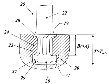
Figure 2 shows an illustration, comparable to that in
Figure 1, of one exemplary embodiment of a
rotor blade mounting according to the
invention.


CA 02548642 2006-06-06

- 4 -
WAYS TO IMPLEMENT THE INVENTION

In the exemplary embodiment of the invention
illustrated in Figure 2, the rotor blade 25 is mounted
in the rotor 20 by means of the blade section 22, the
platform 28 and the blade root 26, by means of a recess
21. In this case as well, side shoulders 24 are once
again formed in the recess 21, behind which the widened
lower part 27 of the blade root 26 engages, and is
supported on the contact surfaces 23 when centrifugal
forces occur.

In order to make it possible to better absorb the load
which occurs in this case on the shoulders 24, and thus
to overcome the life limit which results from strength
problems, the recess 21 is now formed with a recess
depth T which is considerably greater, in particular
more than 10% greater, than the minimum recess depth
Tmin used in the prior art. This makes it possible to
increase the shoulder depth of the shoulders 24 to a
value B which is considerably greater than the shoulder
depth A with the already known mounting as shown in
Figure 1. In the exemplary embodiment shown in Figure
2, the recess depth T is approximately 40% greater than
the minimum recess depth Tmin as has been proven in
practice.

The increase in the recess depth T and in the shoulder
depth B also results in an increase in the height of
the blade root 26. Lengthening the blade root 26
necessarily also increases the blade weight, which
would lead to increased centrifugal forces and thus to
increased mechanical loads on the rotor 20. It is
therefore particularly advantageous for at least a
portion of the weight increase which is caused by the
extension to be counteracted again by suitable
measures. The measures comprise material being cut away


CA 02548642 2006-06-06

- 5 -

on the rotor blade 25 in the area of the blade root 26
by the provision of cutouts at points which are not
critical to the mechanical strength. A first preferred
type of cutout is an elongated hole 19, which passes
through the blade root 26 in the circumferential
direction and extends in the radial direction. The
elongated hole 19 is in this case arranged in the thin
section of the blade root 26, and is located in the
centre, between the two shoulders 24. A second
preferred type of cutout is rounded depressions 29, at
the edge, on the lower face of the lower part 27 of the
blade root 26. Both types of cutouts 19, 29 may
optionally be implemented individually or may be
combined with one another, in order to achieve the
desired reduction in weight by reducing the amount of
material.


CA 02548642 2006-06-06

- 6 -
LIST OF REFERENCE SYMBOLS

10,20 Rotor
11,21 Recess (circumferential groove)
12,22 Blade section
13,23 Contact surface
14,24 Shoulder
15,25 Rotor blade
16,26 Blade root
17,27 Lower part (blade root)
18,28 Platform
19 Elongated hole
29 Depression
A,B Shoulder depth
Tmin Minimum recess depth
T Recess depth

Representative Drawing
A single figure which represents the drawing illustrating the invention.
Administrative Status

For a clearer understanding of the status of the application/patent presented on this page, the site Disclaimer , as well as the definitions for Patent , Administrative Status , Maintenance Fee  and Payment History  should be consulted.

Administrative Status

Title Date
Forecasted Issue Date 2011-04-19
(86) PCT Filing Date 2004-11-26
(87) PCT Publication Date 2005-06-16
(85) National Entry 2006-06-06
Examination Requested 2009-11-20
(45) Issued 2011-04-19
Deemed Expired 2019-11-26

Abandonment History

There is no abandonment history.

Payment History

Fee Type Anniversary Year Due Date Amount Paid Paid Date
Application Fee $400.00 2006-06-06
Maintenance Fee - Application - New Act 2 2006-11-27 $100.00 2006-06-06
Registration of a document - section 124 $100.00 2006-09-11
Maintenance Fee - Application - New Act 3 2007-11-26 $100.00 2007-10-30
Maintenance Fee - Application - New Act 4 2008-11-26 $100.00 2008-10-28
Maintenance Fee - Application - New Act 5 2009-11-26 $200.00 2009-10-08
Request for Examination $800.00 2009-11-20
Maintenance Fee - Application - New Act 6 2010-11-26 $200.00 2010-11-12
Final Fee $300.00 2011-02-01
Maintenance Fee - Patent - New Act 7 2011-11-28 $200.00 2011-10-19
Maintenance Fee - Patent - New Act 8 2012-11-26 $200.00 2012-10-19
Maintenance Fee - Patent - New Act 9 2013-11-26 $200.00 2013-10-15
Maintenance Fee - Patent - New Act 10 2014-11-26 $250.00 2014-11-19
Maintenance Fee - Patent - New Act 11 2015-11-26 $250.00 2015-11-16
Registration of a document - section 124 $100.00 2016-08-04
Maintenance Fee - Patent - New Act 12 2016-11-28 $250.00 2016-11-15
Registration of a document - section 124 $100.00 2017-04-13
Maintenance Fee - Patent - New Act 13 2017-11-27 $250.00 2017-11-13
Owners on Record

Note: Records showing the ownership history in alphabetical order.

Current Owners on Record
ANSALDO ENERGIA IP UK LIMITED
Past Owners on Record
ALSTOM TECHNOLOGY LTD
BACHOFNER, RENE
GENERAL ELECTRIC TECHNOLOGY GMBH
GRIGIONI, PIETRO
KAPPIS, WOLFGANG
Past Owners that do not appear in the "Owners on Record" listing will appear in other documentation within the application.
Documents

To view selected files, please enter reCAPTCHA code :


To view images, click a link in the Document Description column. To download the documents, select one or more checkboxes in the first column and then click the "Download Selected in PDF format (Zip Archive)" or the "Download Selected as Single PDF" button.

List of published and non-published patent-specific documents on the CPD .

If you have any difficulty accessing content, you can call the Client Service Centre at 1-866-997-1936 or send them an e-mail at CIPO Client Service Centre.


Document
Description 
Date
(yyyy-mm-dd) 
Number of pages   Size of Image (KB) 
Abstract 2006-06-06 1 21
Claims 2006-06-06 2 50
Drawings 2006-06-06 2 25
Description 2006-06-06 6 181
Representative Drawing 2006-08-17 1 10
Cover Page 2006-08-24 1 46
Description 2009-11-20 7 212
Claims 2009-11-20 2 51
Abstract 2010-08-23 1 21
Cover Page 2011-03-21 2 49
Assignment 2006-09-11 2 83
PCT 2006-06-06 5 185
Assignment 2006-06-06 4 145
Correspondence 2006-08-15 1 27
Prosecution-Amendment 2009-11-20 2 73
Prosecution-Amendment 2009-11-20 8 244
Correspondence 2011-02-01 2 66
Assignment 2016-08-04 9 349
Assignment 2016-09-20 13 655