Language selection

Search

Patent 2550400 Summary

Third-party information liability

Some of the information on this Web page has been provided by external sources. The Government of Canada is not responsible for the accuracy, reliability or currency of the information supplied by external sources. Users wishing to rely upon this information should consult directly with the source of the information. Content provided by external sources is not subject to official languages, privacy and accessibility requirements.

Claims and Abstract availability

Any discrepancies in the text and image of the Claims and Abstract are due to differing posting times. Text of the Claims and Abstract are posted:

  • At the time the application is open to public inspection;
  • At the time of issue of the patent (grant).
(12) Patent: (11) CA 2550400
(54) English Title: FOOD GRATING DEVICE AND IMPROVED HINGE MECHANISM
(54) French Title: CLAIE ALIMENTAIRE ET ARTICULATION AMELIOREE
Status: Granted
Bibliographic Data
(51) International Patent Classification (IPC):
  • B25G 3/38 (2006.01)
  • A47J 43/25 (2006.01)
(72) Inventors :
  • WEBB, TERRI (United States of America)
  • CHALFANT, LOUIS (United States of America)
(73) Owners :
  • COLUMBIA INSURANCE COMPANY (United States of America)
(71) Applicants :
  • COLUMBIA INSURANCE COMPANY (United States of America)
(74) Agent: NORTON ROSE FULBRIGHT CANADA LLP/S.E.N.C.R.L., S.R.L.
(74) Associate agent:
(45) Issued: 2014-02-11
(22) Filed Date: 2006-06-16
(41) Open to Public Inspection: 2006-12-17
Examination requested: 2011-06-08
Availability of licence: N/A
(25) Language of filing: English

Patent Cooperation Treaty (PCT): No

(30) Application Priority Data:
Application No. Country/Territory Date
60/691,369 United States of America 2005-06-17

Abstracts

English Abstract

The present invention comprises a food triturating device with a first extension, a second extension and a hinge device therebetween. The hinge device is located within a housing, and comprises a hinge bar, a rotating drum mounted on a hinge bar. The rotating drum is slidable between a first position and a second position and rotatable between any one of three rotating positions. The hinge also comprises a engagement wall positioned within the housing and having a shelf and at least one locking slots. A locking member is formed on the rotating drum and cooperates with the engagement wall to lock the rotating drum into any one of the three rotating positions with the rotating drum is in the first sliding position. A biasing spring, located within the housing, biases the rotating drum toward the first sliding position.


French Abstract

La présente invention porte sur un appareil de trituration d'aliments pourvue d'une première rallonge, d'une deuxième rallonge et d'un dispositif charnière entre les deux. Le dispositif charnière est situé dans un boîtier et comprend une aile de charnière, un tambour rotatif fixé sur une aile de charnière. Le tambour rotatif peut coulisser entre une première et une deuxième position et est apte à tourner entre l'une quelconque des trois positions de rotation. La charnière comprend également une paroi de coopération positionnée à l'intérieur du boîtier et comportant une tablette et au moins une fente de verrouillage. Un élément de verrouillage est formé sur le tambour rotatif et coopère avec la paroi de coopération pour bloquer le tambour rotatif dans l'une des trois positions de rotation alors que le tambour est à la première position de coulissement. Un ressort de sollicitation situé dans le boîtier ramène le tambour rotatif à la première position de coulissement.

Claims

Note: Claims are shown in the official language in which they were submitted.


What is claimed is:
1. A hinge assembly for use in connecting a handle to a body member in
multiple operative
positions, the hinge assembly comprising:
a hinge bar engaged to the body member and positioned within a cavity formed
in the
body member;
a rotating drum having a first end and a second end, the rotating drum mounted
on the
hinge bar, slidable between first and second sliding positions and rotatable
between first, second
and third rotating positions;
a locking member formed on the first end of the rotating drum; and
an engagement wall positioned within the cavity, proximate to the first end of
the rotating
drum and comprising a shelf and a locking slot, wherein the shelf cooperates
with the locking
member to selectively lock the rotating drum in either the first or third
locking positions, when
the rotating drum is in the first sliding position, and, alternatively, the
locking slot cooperates
with the locking member to selectively lock the rotating drum in the second
rotating position.
2. The hinge assembly as set forth in Claim 1, further comprising a biasing
spring
positioned between the second end of the rotating drum and the body member,
wherein the
biasing spring biases the rotating drum toward the first sliding position.
3. The hinge assembly as set forth in Claim 2, further comprising a first
cap, removably
secured to the body member proximate to the rotating drum first end, and a
second cap,
removably secured to the body member proximate to the rotating drum second
end.
4. The hinge assembly as set forth in Claim 3, wherein the engagement wall
comprises:
a bottom portion integrally formed from the body member, the bottom portion
comprising a bottom slot portion and the shelf;

a top portion integrally formed from the first cap, the top portion comprising
a top slot
portion and positioned such that the top and bottom slot portions cooperate to
form the locking
slot, and wherein the top portion is dimensioned to allow the locking member
to engage and
cooperate with the shelf
5. The hinge assembly as set forth in Claim 4, wherein the engagement wall
is dimensioned
such that sliding the rotating drum from the first sliding position to the
second sliding position
allows the rotating drum to freely rotate about the hinge bar.
6. A hinge assembly for use with a first and a second member rotatable with
respect to one
another, the hinge assembly comprising:
a housing engaged to the first member;
a hinge bar positioned within the housing and engaged to the first member;
a drum rotatably and slidably disposed on the hinge bar and engaged to the
second
member, the drum comprising a first end and a second end and slidable along
the hinge bar
between a first, locked position and a second, unlocked position;
a locking wall disposed within the housing proximate to the first end of the
drum, the
locking wall comprising at least one locking slot, wherein the at least one
locking slot comprises
a first locking slot wall;
a locking member located on the first end of the drum, the locking member
comprising a
first locking member side extending parallel to the first locking slot wall,
and a second locking
member side extending parallel to the first locking member side, and wherein
the locking
member engages the at least one locking slot when the drum is in the first
position, preventing
the drum from rotating about the hinge bar; and
11

a spring positioned wholly within the housing and engaged to the second end of
the drum
to bias the drum to the first, locked position.
7. The hinge assembly as set forth in Claim 6, wherein the locking wall
comprises a
plurality of locking slots, and wherein the locking member engages one of the
locking slots when
the drum is in the first position, preventing the drum from rotating about the
hinge bar.
8. The hinge assembly as set forth in Claim 6, wherein the drum is
integrally formed from
the second member.
9. The hinge assembly as set forth in Claim 6, wherein the first member
comprises a food
grating surface and the second member comprises a handle.
10. The hinge assembly as set forth in Claim 6, wherein the locking member
comprises a first
portion and a second portion, wherein the second portion is positioned on the
opposite side of the
hinge bar from the first portion.
11. The hinge assembly as set forth in Claim 6, wherein the locking wall
abuts the first end of
the drum when the drum is in the first, locked position.
12. A hinge assembly comprising:
a housing;
a first member engaged to and extending from the housing;
a hinge bar positioned within the housing and engaged to the first member;
a rotating drum comprising a first end and a second end, the rotating drum
being
positioned at least partially within the housing and slidable between a first
position and a second
position, and rotatable with respect to the housing;
a locking wall disposed at least partially in the housing and positioned
proximate to the
first end of the rotating drum, the locking wall comprising at least one
locking slot; and
12

a locking member formed on the first end of the rotating drum and comprising a
first side
extending perpendicular to the first end of the rotating drum, and a second
side extending
perpendicular to the first end of the rotating drum, wherein the locking
member engages the at
least one locking slot when the rotating drum is in the first position,
preventing the rotating drum
from rotating; and
a spring positioned wholly within the housing and engaged to the second end of
the
rotating drum to bias the rotating drum to the first position.
13. The hinge assembly as set forth in Claim 12, wherein the rotating drum
is slidably and
rotatably disposed on the hinge bar.
14. The hinge assembly as set forth in Claim 13, further comprising a
biasing spring disposed
within the housing and engaged to the rotating drum, wherein the biasing
spring biases the
rotating drum to the first position.
15. The hinge assembly as set forth in Claim 12, wherein the locking wall
comprises a
plurality of locking slots, wherein the locking member engages at least one of
the locking slots
when the rotating drum is in the first position, preventing the rotating drum
from rotating.
16. The hinge assembly as set forth in Claim 12, wherein the first member
is integrally
formed with the housing.
17. The hinge assembly as set forth in Claim 16, wherein a second member is
engaged to the
rotating drum.
18. The hinge assembly as set forth in Claim 12, further comprising a first
and a second cap,
wherein the first and the second caps are engaged to the housing.
13

19. The hinge assembly as set forth in Claim 18, wherein the locking wall
comprises a first
portion, integrally formed with the first cap, and a second portion,
integrally formed with the
housing.
20. A hinge assembly comprising:
a housing;
a hinge bar disposed within the housing and engaged to a first member;
a rotating drum positioned at least partially within the housing, the rotating
drum
disposed on the hinge bar and comprising a first end and a second end and
slidable between a
first position and a second position, and rotatable about the hinge bar;
a biasing spring positioned wholly within the housing engaged to the rotating
drum,
wherein the biasing spring biases the rotating drum to the first position;
a second member engaged to and extending from the rotating drum; a locking
wall
positioned proximate to the first end of the rotating drum and disposed within
the housing, the
locking wall comprising at least one locking slot; and
a locking member formed on the first end of the rotating drum, the locking
member
comprising a first side extending perpendicular to the first end of the
rotating drum, and a second
side extending perpendicular to the first end of the rotating drum, wherein
the locking member
engages the at least one locking slot when the rotating drum is in the first
position, preventing the
rotating drum from rotating.
21. The hinge assembly as set forth in Claim 20, wherein the first member
is integrally
formed from the housing and the second member is integrally formed from the
rotating drum.
22. The hinge assembly as set forth in Claim 20, further comprising a first
cap, wherein the
first cap is engaged to the housing.
14


23. The hinge assembly as set forth in Claim 22, wherein the locking wall
comprises a top
half, integrally formed from the first cap, and a bottom half, integrally
formed from the housing.
24. A hinge assembly comprising:
a housing;
a hinge bar disposed within the housing;
a first member rotatably and slidably disposed within the housing and on the
hinge bar,
the first member comprising a first end and a second end and slidable along
the hinge bar
between a first, locked position and a second, unlocked position;
a second member disposed within the housing proximate to the first end of the
first
member;
at least one locking slot disposed in the housing, the at least one locking
slot comprising a
first wall;
a locking member disposed on the first member and comprising a first side
extending
parallel to the first wall of the at least one locking slot, and a second side
extending parallel to
the first wall, wherein the locking member engages the at least one locking
slot when the first
member is in the first position, preventing the first member from rotating
about the hinge bar;
and
a spring engaged to the second end of the first member to bias the first
member to the
first, locked position.
15

Description

Note: Descriptions are shown in the official language in which they were submitted.


CA 02550400 2006-06-16
16659-181 CA
FOOD GRATING DEVICE AND IMPROVED HINGE MECHANISM
Background of the Invention
This invention relates to an apparatus for grating food products as well as a
hinge
mechanism to connect arms of an apparatus in multiple fixed positions.
Summary of the Invention
An apparatus for grating food products, such as cheese, is disclosed herein.
The apparatus
comprises a pair of arms that are fixable in different positions to enable the
apparatus to be easily
used in different manners, and to be easily collapsed into a storage position.
An improved hinge
mechanism that may be used in connection with other devices is also disclosed.
The details of
this invention are set forth below in connection with the detailed description
of the embodiments.
Brief Description of the Drawings
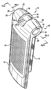
Fig. 1 is an isometric view of an exemplary cheese grater in accordance with
one
embodiment of the present invention, with the handle in a first, closed
position.
Fig. 2 is an isometric view of the cheese grater of Fig. 1, with the handle in
a second
position.
Fig. 3 is an isometric view of the cheese grater of Fig. l, with the handle in
a third
position.
Fig. 4 is a bottom plan view of the cheese grater of Fig. l, with portions of
the housing
removed to show the hinge mechanism, and with the handle in the first closed
position and the
hinge mechanism in the locked position.
Fig. 5 is a bottom plan view similar to Fig. 4, with the hinge mechanism moved
to the
rotating position.
Fig. 6 is a cross sectional view of the cheese grater along the lines 6-6 in
Fig. 2.

CA 02550400 2006-06-16
16659-181CA
Fig. 7 is a cross sectional view of an embodiment of the present invention
along the lines
7-7 in Fig. 3
Fig. 8 is a sectional view of the second cap along lines 8-8 in Fig. 1.
Fig. 9 is a sectional view of the first end cap along lines 9-9 in Fig. 1.
Fig. 10 is a cross sectional view of the engagement wall along lines 10-10 in
Fig. 5 with
the first cap removed.
Fig. 11 is a cross sectional view of the engagement wall similar to Fig. 10,
but with the
first cap attached.
Detailed Description of the Drawings
FIGS.1-7 depict an exemplary food grater 12 having a main body member 14 and
handle
member 16 connected by means of hinge assembly 10. In the embodiment depicted,
main body
member 14 has a food grating surface 18 attached thereto. Handle member 16
comprises
gripping portion 20, neck portion 1 S and rotating drum 50. Indented area 22
is formed on
gripping portion 20 for ease of handling, as the user may place a thumb there
when holding the
gripping portion 20.
Grater 12 has at least three different positions, which are achieved by the
rotation of
handle member 16 through the hinge mechanism 10 to be described below. The
first, or closed,
position is depicted in FIG. 1, where handle member 16 is adjacent the back
surface of grating
surface 18. This permits grater 12 to be stored without taking up a
significant amount of space.
The second position is shown in FIG. 2, where handle member 16 is at a
sufficient angle to main
body member 14 to permit grater 12 to stand on its own on a table, plate or
other surface. The
user can still hold grater 12 by holding the gripping portion 20 of handle
member 16 in this
configuration. The third position is shown in FIG. 3, where handle member 16
is extended
2

CA 02550400 2006-06-16
16659-181 CA
parallel to main body member 14 and grating surface 18; this configuration is
particularly helpful
if the user wishes to grate the food product into a larger bowl or other area.
It will be appreciated by those in the art that the figures depict an
exemplary embodiment
rather than a limiting one. For example, this apparatus is described as a food
grater but other
applications are possible. Grating surface 18 may also be removably attached
to permit different
grating or slicing surfaces to be used with the apparatus, and handle member
16 may comprise
different shapes than gripping portion 20. Moreover, hinge assembly 10 has
many applications
and is not limited to applications such as food grater 12, nor is it limited
to use with food-related
utensils, as there are industrial applications for such assemblies.
Curved portion 25, having a first end 26 and a second end 28, is formed at one
end of
main body member 14. Cavity 36 is formed within curved portion 25. Caps 31 and
32 are
removably secured to curved portion 25 proximate to first end 26 and second
end 28,
respectively. Cap 31 comprises circular element 91, while cap 32 comprises
circular element 92.
Groove 35 is formed between first end 26 and cap 31 on the one side, and
second end 28
and cap 32 on the other side. Groove 35 is sized to accommodate neck portion
15 to permit
handle member 16 to move between the first, second and third positions as
described herein.
In the embodiment depicted, curved portion 25 is integrally formed as part of
main body
member 14; other means of securing curved portion 25 to main body member 14
are within the
scope of the invention. Similarly, caps 31 and 32 are removably secured to
curved portion 25 by
means of screws (not shown) threaded into openings 39; covers (not shown) may
be used to
enclose the screws to provide a smooth outer surface of caps 31 and 32. It
will be understood
that caps 31 and 32 may be removably secured by other means such as snaps, a
tongue-in-groove
arrangement, etc. It will also be appreciated that the depicted embodiment is
exemplary only,
3

CA 02550400 2006-06-16
16659-181 CA
rather than limiting, and it is within the scope of the present invention that
curved portion 25 and
caps 31 and 32 may be replaced by a number of variations.
As shown in FIGS. 4 and 5, hinge assembly 10 comprises first collar 41 located
in cavity
36 near first end 26 and second collar 42 located in cavity 36 near second end
28. Hinge bar 43
comprises a first end 44, which is secured within first collar 41, and a
second end 45, which is
secured within second collar 42.
Rotating drum 50, having a drum first end 51 and a drum second end 52, is
preferably an
integral part of handle 16 and is mounted on hinge bar 43. Biasing spring 60
is located on hinge
bar 43 between drum second end 52 and second collar 42. As can be seen by a
comparison of
FIGS. 4 and 5, rotating drum 50 (and therefore handle member 16) is slidably
mounted on hinge
bar 43 and is movable between a first, locked position shown in FIG. 4, and a
second, rotatable
position shown in FIG. 5. Moving rotating drum 50 to the second, unlocked
position enables the
user to rotate neck portion 15 of handle member 16 through groove 35 to move
handle member
16 to the different operating positions described herein. Biasing spring 60 is
positioned such that
it biases rotating drum 50 to the first, locked position.
A locking member 55 is formed on drum first end 51. As shown, for example, in
FIG. 5,
locking member 55 comprises a body portion 62 and end portions 63. In the
depicted
embodiment, body portion 62 is formed about hinge bar 43. Because the width of
body portion
62 is less than the diameter of hinge bar 43, body portion 62 appears to be
two separate pieces. It
will be appreciated by those in the art that the depicted embodiment of
locking member 55 is
exemplary rather than limiting. For example, the width of body portion 62 may
be greater than
the diameter of hinge bar 43. Also, locking member 55 may solely comprise body
portion 62,
and not end portions 63, or solely comprise end portions 63 and not body
portion 62. Finally, as
4

CA 02550400 2006-06-16
16659-181 CA
described below, when cap 31 is attached to curved portion 25, locking member
55 need not
extend to both sides of hinge bar 43.
As seen in FIG. 5, an engagement wall 70 is located within cavity 36 proximate
to drum
first end 51. As seen in FIG. 11, engagement wall 70 comprises at least two
locking slots, 75
and 81. Locking member SS m a first end 26 and a second end 28, is formed at
one end of main
body member 14. Cavity 36 is formed within curved portion 25. Caps 31 and 32
are removably
secured to curved portion 25 proximate to first end 26 and second end 28,
respectively. Cap 31
comprises circular element 91, while cap 32 comprises circular element 92.
Groove 35 is formed between first end 26 and cap 31 on the one side, and
second end 28
and cap 32 on the other side. Groove 35 is sized to accommodate neck portion
15 to permit
handle member 16 to move between the first, second and third positions as
described herein.
In the embodiment depicted, curved portion 25 is integrally formed as part of
main body
member 14; other means of securing curved portion 25 to main body member 14
are within the
scope of the invention. Similarly, caps 31 and 32 are removably secured to
curved portion 25 by
means of screws (not shown) threaded into openings 39; covers (not shown) may
be used to
enclose the screws to provide a smooth outer surface of caps 31 and 32. It
will be understood
that caps 31 and 32 may be removably secured by other means such as snaps, a
tongue-in-groove
arrangement, etc. It will also be appreciated that the depicted embodiment is
exemplary only,
rather than limiting, and it is within the scope of the present invention that
curved portion 25 and
caps 31 and 32 may be replaced by a number of variations.
As shown in FIGS. 4 and 5, hinge assembly 10 comprises first collar 41 located
in cavity
36 near first end 26 and second collar 42 located in cavity 36 near second end
28. Hinge bar 43
5

CA 02550400 2006-06-16
16659-181 CA
comprises a first end 44, which is secured within first collar 41, and a
second end 45, which is
secured within second collar 42.
Rotating drum 50, having a drum first end 51 and a drum second end 52, may be
an
integral part of handle 16 and is mounted on hinge bar 43. Biasing spring 60
is located on hinge
bar 43 between drum second end 52 and second collar 42. As can be seen by a
comparison of
FIGS. 4 and 5, rotating drum 50 (and therefore handle member 16) is slidably
mounted on hinge
bar 43 and is movable between a first, locked position shown in FIG. 4, and a
second, rotatable
position shown in FIG. 5. Moving rotating drum 50 to the second, rotatable
position enables the
user to rotate neck portion 15 of handle member 16 through groove 35 to move
handle member
16 to the different operating positions described herein. Biasing spring 60 is
positioned such that
it biases rotating drum 50 to the first, locked position.
A locking member 55 is formed on drum first end 51. As shown, for example, in
FIG. 5,
locking member 55 comprises a body portion 62 and end portions 63. In the
depicted
embodiment, body portion 62 is formed about hinge bar 43. Because the width of
body portion
62 is less than the diameter of hinge bar 43, body portion 62 appears to be
two separate pieces. It
will be appreciated by those in the art that the depicted embodiment of
locking member 55 is
exemplary rather than limiting. For example, the width of body portion 62 may
be greater than
the diameter of hinge bar 43. Also, locking member 55 may solely comprise body
portion 62,
and not end portions 63, or solely comprise end portions 63 and not body
portion 62. Finally, as
described below, when cap 31 is attached to curved portion 25, locking member
55 need not
extend to both sides of hinge bar 43.
As seen in FIG. 5, an engagement wall 70 is located within cavity 36 proximate
to drum
first end S 1. As seen in FIG. 11, engagement wall 70 comprises at least two
locking slots, 75
6

CA 02550400 2006-06-16
16659-181 CA
and 81. Locking member 55 may cooperate with either locking slot 75 in the
second rotating
position (as described in detail below) or slot 81 in the first or third
rotating positions (as
described in detail below). The cooperation of locking member SS and either
slot 75 or 81 will
prevent rotating drum SO from rotating about hinge bar 43. It will be obvious
that multiple
locking slots may be formed within engagement wall 70, where each locking slot
will cooperate
with locking member 55 to prevent the rotation of rotating drum 50.
As shown most clearly in FIG. 10, engagement wall 70 may be comprised of two
halves,
where the bottom half 79 is integrally formed from curve portion 25, and the
top half 77 is
integrally formed from cap 31. Bottom half 79 and top half 77 are positioned
such that they
form engagement wall 70.
In order for food grating device 12 to operate, a force that is sufficient to
overcome the
force supplied by biasing spring 60 is applied, to the left as depicted in
FIG. 5, to rotating drum
50 through handle member 16. In use, a user will supply this force by pressing
on the end
portion formed by cap 32 and end 26 with his or her thumb while grasping
handle 16. This force
slides rotating drum 50 to the second, rotatable position, where rotating drum
SO is free to rotate
about hinge bar 43. While rotating drum 50 is in the second, unlocked
position, the user rotates
handle member 16 slightly towaxd the second rotating position, likewise
revolving rotating drum
50 toward the second rotating position, as depicted in FIG. 6. When locking
member 55 is no
longer aligned with shelf 73, the force on handle 20 is removed. The force
from biasing spring
60 will urge rotating drum 50 toward first sliding position 54, which will
cause locking member
SS to abut face 74 of engagement wall 70.
As the user rotates handle member 16, and consequently rotating drum 50,
toward the
second rotating position, locking member 55 will slide along face 74 until it
aligns with locking
7

CA 02550400 2006-06-16
16659-181 CA
slot 75. When locking member 55 aligns with locking slot 75, spring 60 will
urge locking
member 55 to engage and cooperate with locking slot 75, allowing rotating drum
50 to return to
the first, locked sliding position. As in the first rotating position, when
rotating drum 50 is in the
second rotating position, the cooperation of locking member 55 and locking
slot 75 will prevent
rotating drum SO from rotating about hinge bar 43.
When the user once again supplies a sufficient force to rotating drum 50
through handle
member 16 (again by pressing on cap 32 while grasping handle 16), rotating
drum 50 slides to
the second, unlocked position, where rotating drum SO is again free to rotate
about hinge bar 43.
While rotating drum 50 is in this second unlocked position, the user slightly
rotates handle 16
toward the third rotating position, as shown in FIG. 7. When locking member 55
is no longer
aligned with locking slot 75, the force on handle member 16 is removed. The
force from biasing
spring 60 will again urge rotating drum 50 toward the first, locked sliding
position, which will
cause locking member 55 to abut face 74.
As rotating drum 50 continues to rotate, locking member 55 will slide along
face 74 until
it once again aligns with shelf 73, at which time biasing spring 60 will urge
rotating drum 50 to
return to first, locked sliding position, where shelf 73 and locking member 55
once again
cooperate to prevent rotating drum 50 from rotating about hinge bar 43.
It will be appreciated by those in the art that the use of any of the rotating
positions is
optional and not necessary for the use of the present invention. By way of
example, rotating
drum 50, while in the second unlocked position, may be rotated from the first
rotating position to
slightly past the second rotating position before the force acting on handle
member 16 is
removed. In this way, rotating drum 50 may be rotated from the first rotating
position directly to
the third rotating position.
8

CA 02550400 2006-06-16
16659-181 CA
It will also be appreciated that more than one locking slot may be formed in
engagement
wall 70. Because any additional locking slots will cooperate with locking
member SS in the
same way as locking slot 75, the number of additional locking slots would
allow rotating drum
50 to rotate between the same number of additional rotating positions.
While specific embodiments of the invention have been described in detail, it
will be
appreciated by those skilled in the art that various modifications and
alternatives to those details
could be developed in light of the overall teachings of the disclosure.
Accordingly, the particular
arrangements of the food grating device and hinge disclosed are meant to be
illustrative only and
not limiting as to the scope of the invention which is to be given the full
breadth of the appended
claims and any equivalents thereof.
9

Representative Drawing
A single figure which represents the drawing illustrating the invention.
Administrative Status

For a clearer understanding of the status of the application/patent presented on this page, the site Disclaimer , as well as the definitions for Patent , Administrative Status , Maintenance Fee  and Payment History  should be consulted.

Administrative Status

Title Date
Forecasted Issue Date 2014-02-11
(22) Filed 2006-06-16
(41) Open to Public Inspection 2006-12-17
Examination Requested 2011-06-08
(45) Issued 2014-02-11

Abandonment History

There is no abandonment history.

Maintenance Fee

Last Payment of $473.65 was received on 2023-05-24


 Upcoming maintenance fee amounts

Description Date Amount
Next Payment if small entity fee 2024-06-17 $253.00
Next Payment if standard fee 2024-06-17 $624.00

Note : If the full payment has not been received on or before the date indicated, a further fee may be required which may be one of the following

  • the reinstatement fee;
  • the late payment fee; or
  • additional fee to reverse deemed expiry.

Patent fees are adjusted on the 1st of January every year. The amounts above are the current amounts if received by December 31 of the current year.
Please refer to the CIPO Patent Fees web page to see all current fee amounts.

Payment History

Fee Type Anniversary Year Due Date Amount Paid Paid Date
Registration of a document - section 124 $100.00 2006-06-16
Application Fee $400.00 2006-06-16
Maintenance Fee - Application - New Act 2 2008-06-16 $100.00 2008-05-14
Maintenance Fee - Application - New Act 3 2009-06-16 $100.00 2009-06-04
Maintenance Fee - Application - New Act 4 2010-06-16 $100.00 2010-06-07
Maintenance Fee - Application - New Act 5 2011-06-16 $200.00 2011-06-01
Request for Examination $800.00 2011-06-08
Maintenance Fee - Application - New Act 6 2012-06-18 $200.00 2012-05-31
Maintenance Fee - Application - New Act 7 2013-06-17 $200.00 2013-04-04
Final Fee $300.00 2013-11-27
Maintenance Fee - Patent - New Act 8 2014-06-16 $200.00 2014-06-09
Maintenance Fee - Patent - New Act 9 2015-06-16 $200.00 2015-06-15
Maintenance Fee - Patent - New Act 10 2016-06-16 $250.00 2016-06-13
Maintenance Fee - Patent - New Act 11 2017-06-16 $250.00 2017-05-23
Maintenance Fee - Patent - New Act 12 2018-06-18 $250.00 2018-05-23
Maintenance Fee - Patent - New Act 13 2019-06-17 $250.00 2019-06-03
Maintenance Fee - Patent - New Act 14 2020-06-16 $250.00 2020-05-25
Maintenance Fee - Patent - New Act 15 2021-06-16 $459.00 2021-05-19
Maintenance Fee - Patent - New Act 16 2022-06-16 $458.08 2022-05-20
Maintenance Fee - Patent - New Act 17 2023-06-16 $473.65 2023-05-24
Owners on Record

Note: Records showing the ownership history in alphabetical order.

Current Owners on Record
COLUMBIA INSURANCE COMPANY
Past Owners on Record
CHALFANT, LOUIS
WEBB, TERRI
Past Owners that do not appear in the "Owners on Record" listing will appear in other documentation within the application.
Documents

To view selected files, please enter reCAPTCHA code :


To view images, click a link in the Document Description column. To download the documents, select one or more checkboxes in the first column and then click the "Download Selected in PDF format (Zip Archive)" or the "Download Selected as Single PDF" button.

List of published and non-published patent-specific documents on the CPD .

If you have any difficulty accessing content, you can call the Client Service Centre at 1-866-997-1936 or send them an e-mail at CIPO Client Service Centre.


Document
Description 
Date
(yyyy-mm-dd) 
Number of pages   Size of Image (KB) 
Abstract 2006-06-16 1 20
Description 2006-06-16 9 372
Claims 2006-06-16 4 126
Drawings 2006-06-16 6 162
Representative Drawing 2006-11-21 1 13
Cover Page 2006-12-05 2 50
Claims 2011-06-08 8 297
Claims 2013-03-27 6 227
Claims 2013-09-23 6 219
Cover Page 2014-01-15 1 46
Assignment 2006-06-16 5 246
Prosecution-Amendment 2011-06-08 10 361
Prosecution-Amendment 2011-06-08 12 444
Prosecution-Amendment 2012-11-09 2 49
Prosecution-Amendment 2013-03-27 8 301
Prosecution-Amendment 2013-07-15 2 77
Prosecution-Amendment 2013-09-23 9 355
Correspondence 2013-11-27 2 69