Note: Descriptions are shown in the official language in which they were submitted.
CA 02552570 2006-07-04
WO 2005/069328 PCT/F12005/000028
SWITCHING DEVICE
BACKGROUND OF THE INVENTION
[0001] The invention relates to a switching device according to the
preamble of the independent claim.
[0002] Switching devices are equipment used for opening and clos-
ing a current circuit. A switching device comprises at least one pole and a
con-
trol device arranged to open and close this pole. Switching devices include
e.g.
switches and switch-fuses.
[0003] When a current circuit is opened, an electric arc whose tem-
perature is thousands of degrees may occur in a switching device. An electric
arc includes ionized gas which contains a large number of free electrons. Such
a gas plasma is electrically conductive.
[0004] In addition to the electric arc being conductive, metal which
has been vaporized from contacts by the electric arc may, upon solidification,
impair the insulation capacity of the surfaces of the switching device. Soot
pro-
duced by the electric arc may also cause insulation problems.
[0005] Switching devices wherein air is used as an insulating mate-
rial comprise a discharge route for heated air. The discharge route enables
expanded gas to discharge from the frame of the switching device, which pre-
vents pressure inside the switching device from becoming too high.
[0006] A problem with the known switching devices is that in con-
nection with a switching event, gas discharging from the frame of the
switching
device may cause an earth fault between a live part of the switching device
and an adjacent earthed part.
BRIEF DESCRIPTION OF THE INVENTION
[0007] An object of the invention is to provide a switching device to
enable the above-described problem to be alleviated. The object of the inven-
tion is achieved by a switching device which is characterized by what is dis-
closed in the independent claim. Preferred embodiments of the invention are
disclosed in the dependent claims.
[0008] The idea underlying the invention is that in its part remaining
inside the frame, a connector of the switching device is equipped with a hole
arranged for a gas flow.
CA 0 255257 0 2 0 1 2-1 0-0 9
2
[0009] An advantage of the switching device according to the inven-
tion is that disadvantages in a switching device caused by discharging gases
are minimized.
BRIEF DESCRIPTION OF THE DRAWINGS
In the following the invention will be described in greater detail by
means of preferred embodiments with reference to the accompanying Figure
1, which shows a cross-section of a switching device according to an
embodiment of the invention.
DETAILED DESCRIPTION OF THE INVENTION
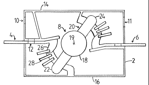
[0010] The switching device of Figure 1 is in an open position, i.e. in
a position wherein a current circuit connected thereto is open.
[0011] The switching device of Figure 1 comprises a frame 2 having
an upper part 14 and a lower part 16. The frame 2 is provided with a first con-
nector 4, a second connector 6 and means 8 for electrically connecting the
first
4 and the second 6 connector with one another. The first connector 4 and the
second connector 6 extend from inside the frame 2 outside the frame. The
connectors 4 and 6 are formed from a substantially planar preform by bending.
The switching device is connected to the current circuit it is adapted to open
and close by the first connector 4 and the second connector 6.
[0012] The frame 2 is preferably manufactured from an electrically
insulating material, such as plastics.
[0013] The frame 2 is provided with two gas flow openings. The gas
flow openings 10 and 11 are arranged to allow gas to flow between the inner
part and the surrounding environment of the frame. The first gas flow opening
resides above the first connector 4 while the second gas flow opening 11
resides above the second connector 6. Each gas flow opening resides on the
same side of the frame 2 as the corresponding connector.
[0014] In its part remaining inside the frame 2, the first connector 4
is provided with a hole 12 for a gas flow. A part of the frame 2 adjacent to
the
connector 4 is provided with an opening for a gas flow corresponding with the
hole 12.
[0015] The second connector 6 is identical with the first connector 4,
so the switching device necessitates connectors of only one kind to be manu-
factured.
CA 02552570 2012-10-09
3
[0016] The gas flow openings 10 and 11 reside at the upper part 14
of the frame. The switching device is mounted in its mounting space, such as a
switchgear cubicle, such that the lower part 16 of the switching device
resides
closer to frame structures of the mounting space than the upper part 14 of the
switching device does. The gas flow openings 10 and 11 thus reside farther
from the frame structures of the mounting space than the first connecter 4 and
the second connector 6 do.
[0017] An inner end of each connector 4 and 6 is provided with a
projection 26 which extends at a substantially perpendicular plane with
respect
to the rest of the corresponding connector. The projection 26 of the first con-
nector 4 extends downwards with respect to the other parts of the connector 4
while the projection 26 of the second connector 6 extends upwards with re-
spect to the other parts of the connector 6.
[0018] The means 8 for electrically connecting the first connector 4
and the second connector 6 with one another comprise a roll 18 and a pair of
contacts 20 attached thereto. The pair of contacts comprises two juxtaposed
contacts 20, of which Figure 1 shows one. The roll 18 is rotatably mounted
with
respect to the frame 2.
[0019] When the current circuit is closed, a first end 22 of the con-
tacts 20 is in contact with the first connector 4 while a second end 24 of the
contacts is in contact with the second connector 6. Each projection 26 thus
almost completely resides between, and in contact with, the ends of the con-
tacts 20.
[0020] The current circuit is opened by rotating the roll 18 around its
rotation axis 19 anticlockwise to a position wherein the contacts 20 are not
in
contact with the connectors 4 and 6. Upon opening the current circuit, a con-
ductive gas plasma is generated, as mentioned above. A rise in temperature
increases the pressure of the air inside the frame 2. The pressure is allowed
to
discharge through the gas flow openings 10 and 11. The gas flow openings 10
and 11 differ in the size of their cross-sectional area. The surface area of
each
said gas flow opening is dimensioned such that in a switching situation, the
velocity of gas discharging out of each gas flow opening is substantially the
same.
[0021] During a switching event, a gas plasma corresponding with
the first connector 4 is generated beneath the first connector 4. As stated
above, the gas flow channel corresponding with the first connector comprises a
CA 02552570 2012-10-09
4
hole 12 provided in the first connector 4 to enable hot gases to flow towards
the gas flow opening 10. Since the connector 4 is made of metal, it
contributes
to cooling down the flowing gas. The gas flow is also cooled down when it hits
metallic arc extinguisher plates 28.
[0022] The hole 12 of the connector 4 may be the only possible
route for gases when they flow towards the gas flow opening 10. In a modular
switching device, for instance, the width of the connectors 4 and 6 may be al-
most equal to the inner width of the frame 2 of the module. Consequently, no
extra room is left for a gas flow channel. A width direction herein refers to
a
direction parallel to the rotation axis 19.
[0023] The gas flow channels through which hot gases generated
by a switching event flow towards the gas flow openings 10 and 11 are de-
signed such that the gases have cooled down sufficiently upon discharge from
the frame 2. The cooler the discharging gas, the less electrically conductive
it
is. The discharging gas being poorly electrically conductive is advantageous
as
far as the insulation characteristics of the switching device are concerned.
Inreasing the length of the flow route and adding heat absorbing structures
along the flow route for gases lower their temperature.
[0024] During a switching event, a gas plasma corresponding with
the second connector 6 is generated above the second connector 6. Conse-
quently, the connector 6 does not reside in the flow route of gases.
Therefore,
the structures of the frame 2 are provided with no opening corresponding with
a hole 12 of a connector 6. The gases are thus not allowed to flow through the
hole 12 of the second connector 6. The fact that the frame 2 necessitates no
opening corresponding with a hole 12 of a connector 6 makes the frame 2
stiffer.
[0025] A flow channel corresponding with the first connector 4
through which gases generated in a switching situation progress to the gas
flow opening 10 is relatively long and its volume is relatively large. A flow
channel corresponding with the second connector 6, in turn, is relatively
short
and its volume is small as compared with the flow channel corresponding with
the first connector 4.
[0026] The cross section of the gas flow opening 10 in the vicinity of
the first connector 4 is smaller than that of the gas flow opening 11 in the
vicini-
ty of the second connector 6. In the dimensioning of the cross section of a
gas
flow opening corresponding with each connector, the volume and shape of a
CA 02552570 2012-10-09
corresponding gas flow channel have been taken into account such that in a
switching situation, the velocity of gas discharging out of each gas flow open-
ing is substantially the same.
[0027] The frame structures of a mounting space for a switching de-
vice may be earthed. It is advantageous to position the gas flow openings 10
and 11 at the upper part 14 of the frame 2 so that discharging gases in a
switching situation do not exit the frame 2 in between a live connector and
the
frame structures of the mounting space. The conductive gas being discharged
between a live conductor and an earthed structure of the mounting space
could cause a danger of an earth fault which, by positioning of the gas flow
openings 10 and 11 as shown in Figure 1, can thus be prevented.
[0028] The gases generated by a switching event may form a layer
containing soot, metallic particles and other corresponding residual material
onto surfaces external to the frame 2 which, as the number of switching events
increase, grows thicker and starts to spread, thus impairing the insulation
characteristics of the switching device. Therefore it is also advantageous to
position the gas flow openings 10 and 11 as shown in Figure 1. In addition to
the gas flow openings 10 and 11 residing far away from the earthed parts,
each connector contributes to preventing gases from flowing between a con-
nector and an earthed part. This characteristic is enhanced by the connectors
4 and 6 being substantially wider than the gas flow openings 10 and 11.
[0029] The smaller the frame 2 and the higher the voltages used,
the more important it is to position the gas flow openings such that no gas
generated in a switching situation is allowed to flow in between a live
connect-
or and an earthed part. The same applies to sufficient cooling of gases before
discharge.
[0030] The above-described structure enables the size of a switch-
ing device to be decreased and the switching device to be mounted closer to
the earthed parts of the mounting space. The characteristics are advantageous
as far as use of space is concerned.
[0031] In addition to taking a danger of an earth fault between a live
connector and an earthed part into account in the design and positioning of
gas flow openings, a danger of short circuit between phases is, of course,
also
to be taken into account. Gas discharging out of the frame of a switching de-
vice is not to be conducted in between live phase connectors such that the
connectors would be short-circuited. As to the danger of short circuit between
CA 02552570 2012-10-09
6
connectors, all live components coupled thereto, such as bolts used for con-
necting cables or busbars, are, of course, to be taken into account. A danger
of
direct short circuit between gas flows of different phases of a switching
device
is also to be taken into account in designing and positioning gas flow
openings.
[0032] It is obvious to one skilled in the art that the basic idea of the
invention can be implemented in many different ways. While embodiments of
the invention have been described in the detailed description, the scope of
the
claims should not be limited by the preferred embodiments set forth in the ex-
amples, but should be given the broadest interpretation consistent with the de-
scription as a whole.