Note: Descriptions are shown in the official language in which they were submitted.
CA 02554367 2010-03-29
APPARATUS FOR AND PROCESS OF MATERIAL WEB FORMATION ON
A STRUCTURED FABRIC IN A PAPER MACHINE
BACKGROUND OF THE INVENTION
1. Field of the invention.
The present invention relates to a method of forming a structured fiber
web on a paper machine, and, more particularly, to a method and apparatus
of forming a structured fiber web on a structured fabric in a paper machine.
2. Description of the related art.
In a wet molding process, a structured fabric in a Crescent Former
configuration impresses a three dimensional surface on a web while the
fibrous web is still wet. Such an invention is disclosed in International
Publication No. WO 03/062528 Al. A suction box is disclosed for the purpose
of shaping the fibrous web while wet to generate the three dimensional
structure by removing air through the structural fabric. It is a physical
displacement of portions of the fibrous web that leads to the three
dimensional
surface. Similar to the aforementioned method, a through air drying (TAD)
technique is disclosed in U. S. Patent No. 4,191, 609. The TAD technique
discloses how an already formed web is transferred and molded into an
impression fabric. The transformation takes place on a web having a sheet
solids level greater that 15%. This results in a low density pillow area in
the
fibrous web. These pillow areas are of a low basis weight since the already
formed web is expanded to fill the valleys thereof. The impression of the
fibrous web into a pattern, on an impression fabric, is carried out by passing
a
vacuum through the impression fabric to mold the fibrous web.
1
CA 02554367 2010-03-29
What is needed in the art is a method to produce a fibrous web with a
high basis weight pillow area of low density to thereby increase the
absorption
and bulk characteristics of the finished fibrous web.
SUMMARY OF THE INVENTION
The present invention provides a method of producing a structured
fibrous web having a high basis weight pillow area of low density on a paper
machine using a structured fabric.
The invention comprises, in one form thereof, a method of forming a
structured web including the steps of providing a fiber slurry through a
headbox to a nip formed by a structured fabric and a forming fabric and
collecting fibers from the fiber slurry in at least one valley of the
structured
fabric.
An advantage of the present invention is that the low density pillow
areas have a relatively higher fiber basis weight than that provided with
other
methods.
Another advantage is that the ratio of the uncompressed fiber mass to
the compressed fiber mass is much higher, with the same overall basis weight
than was achievable in the prior art.
Yet another advantage is that the fibrous web formed by the method of
the present invention allows for a superior transfer of the web to a Yankee
drying surface.
2
CA 02554367 2010-03-29
Still yet another advantage of the present invention is that hood
associated with the Yankee dryer can utilize a higher temperature for drying
the pillow portions of the fibrous web, without burning the pillow portions.
An additional advantage of the present invention is that the structured
fabric can have deeper valleys or pockets than a prior art fabric, since the
pillow portions of the fibrous web are thicker and have a higher basis weight,
eliminating the pin hole problems associated with prior art methods, which
results in a thicker more absorbent web.
BRIEF DESCRIPTION OF THE DRAWINGS
The above-mentioned and other features and advantages of this
invention, and the manner of attaining them, will become more apparent and
the invention will be better understood by reference to the following
description of embodiments of the invention taken in conjunction with the
accompanying drawings, wherein:
Fig. 1 is a cross-sectional schematic diagram illustrating the formation
of a structured web using an embodiment of a method of the present
invention;
Fig. 2 is a cross-sectional view of a portion of a structured web of a
prior art method;
Fig. 3 is a cross-sectional view of a portion of the structured web of an
embodiment of the present invention as made on the machine of Fig. 1;
3
CA 02554367 2006-07-25
WO 2005/075737 PCT/EP2005/050203
Fig. 4 illustrates the web portion of Fig. 2 having subsequently gone through
a
press drying operation;
Fig. 5 illustrates a portion of the fiber web of the present invention of Fig.
3
having subsequently gone through a press drying operation;
Fig. 6 illustrates a resulting fiber web of the forming section of the present
invention;
Fig. 7 illustrates the resulting fiber web of the forming section of a prior
art
method;
Fig. 8 illustrates the moisture removal of the fiber web of the present
invention;
Fig. 9 illustrates the moisture removal of the fiber web of a prior art
structured
web;
Fig. 10 illustrates the pressing points on a fiber web of the present
invention;
Fig. 11 illustrates pressing points of prior art structured web;
Fig. 12 illustrates a schematical cross -sectional view of an embodiment of a
papermaking machine of the present invention;
Fig. 13 illustrates a schematical cross -sectional view of another embodiment
of a
papermaking machine of the present invention;
Fig. 14 illustrates a schematical cross -sectional view of another embodiment
of a
papermaking machine of the present invention;
Fig. 15 illustrates a schematical cross -sectional view of another embodiment
of a
papermaking machine of the present invention;
Fig. 16 illustrates a schematical cross -sectional view of another embodiment
of a
papermaking machine of the present invention;
4
CA 02554367 2010-03-29
Fig. 17 illustrates a schematical cross-sectional view of another
embodiment of a papermaking machine of the present invention; and
Fig. 18 illustrates a schematical cross-sectional view of another
embodiment of a papermaking machine of the present invention.
Corresponding reference characters indicate corresponding parts
throughout the several views. The exemplifications set out herein illustrate
one preferred embodiment of the invention, in one form, and such
exemplifications are not to be construed as limiting the scope of the
invention
in any manner.
DETAILED DESCRIPTION OF THE INVENTION
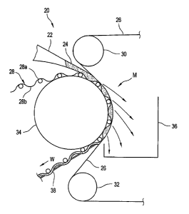
Referring now to the drawings, and more particularly to Fig. 1, there is
a fibrous web machine 20 including a headbox 22 that discharges a fibrous
slurry 24 between a forming fabric 26 and a structured fabric 28. Rollers 30
and 32 direct fabric 26 in such a manner that tension is applied thereto,
against slurry 24 and structured fabric 28.
Structured fabric 28 is supported by forming roll 34 which rotates with a
surface speed that matches the speed of structured fabric 28 and forming
fabric 26. Structured fabric 28 has peaks 28a and valleys 28b, which give a
corresponding structure to web 38 formed thereon. Structured fabric 28
travels in direction W, and as moisture M is driven from fibrous slurry 24,
structured fibrous web 38 takes form. Moisture M that leaves slurry 24 travels
through forming fabric 26 and is collected in save-all 36. Fibers in fibrous
slurry 24 collect predominately in valleys 28b as web 38 takes form.
CA 02554367 2010-03-29
Structured fabric 28 includes warp and weft yarns interwoven on a
textile loom. Structured fabric 28 may be woven flat or in an endless form.
The final mesh count of structured fabric 28 lies between 95 x 120 and 26 x
20. For the manufacture of toilet tissue, the preferred mesh count is 51 x 36
or higher and more preferably 58 x 44 or higher. For the manufacturer of
paper towels, the preferred mesh count is 42 x 31 or lower, and more
preferably 36 x 30 or lower. Structured fabric 28 may have a repeated pattern
of 4 shed and above repeats, preferably 5 shed or greater repeats. The warp
yarns of structured fabric 28 have diameters of between 0.12 mm and 0.70
mm, and weft yarns have diameters of between 0.15 mm and 0.60 mm. The
pocket depth, which is the offset between peak 28a and valley 28b is between
approximately 0.07 mm and 0.60 mm. Yarns utilized in structured fabric 28
may be of any cross-sectional shape, for example, round, oval or flat. The
yarns of structured fabric 28 can be made of thermoplastic or thermoset
polymeric materials of any color. The surface of structured fabric 28 can be
treated to provide a desired surface energy, thermal resistance, abrasion
resistance and/or hydrolysis resistance. A printed design, such as a screen
printed design, of polymeric material can be applied to structured fabric 28
to
enhance its ability to impart an aesthetic pattern into web 38 or to enhance
the quality of web 38. Such a design may be in the form of an elastomeric
cast structure similar to the Spectra membrane described in another patent
application. Structured fabric 28 has a top surface plane contact area at peak
28a of 10% or higher, preferably 20% or higher, and more preferably 30%
depending upon the particular product being made. The contact area on
structured web 28 at peak 28a can be increased by abrading the top surface
of structured fabric 28 or an elastomeric cast structure can be formed thereon
6
CA 02554367 2010-03-29
having a flat top surface. The top surface may also be hot calendered to
increase the flatness.
Forming roll 34 is preferably solid. Moisture travels through forming
fiber 26 but not through structured fabric 28. This advantageously forms
structured fibrous web 38 into a more bulky or absorbent web than the prior
art.
Prior art methods of moisture removal, remove moisture through a
structured fabric by way of negative pressure. It results in a cross-sectional
view as seen in Fig. 2. Prior art structured web 40 has a pocket depth D which
corresponds to the dimensional difference between a valley and a peak. The
valley occurring at the point where measurement C occurs and the peak
occurring at the point where measurement A is taken. A top surface thickness
A is formed in the prior art method. Sidewall dimension B and pillow thickness
C of the prior art result from moisture drawn through a structured fabric.
Dimension B is less than dimension A and dimension C is less than
dimension B in the prior art structure.
In contrast, structured web 38, as illustrated in Figs. 3 and 5, have for
discussion purposes, a pocket depth D that is similar to the prior art.
However,
sidewall thickness B' and pillow thickness C' exceed the comparable
dimensions of web 40. This advantageously results from the forming of
structural web 38 on structured fabric 28 at low consistency and the removal
of moisture is an opposite direction from the prior art. This results in a
thicker
pillow dimension C'. Even after fiber web 38 goes through a drying press
operation, as illustrated in Fig. 5, dimension C' is substantially greater
than
7
CA 02554367 2010-03-29
Ap'. Advantageously, the fiber web resulting from the present invention has a
higher basis weight in the pillow areas as compared to prior art. Also, the
fiber to fiber bonds are not broken as they can be in impression operations,
which expand the web into the valleys.
According to prior art an already formed web is vacuum transferred into
a structured fabric. The sheet must then expand to fill the contour of the
structured fabric. In doing so, fibers must move apart. Thus the basis weight
is lower in these pillow areas and therefore the thickness is less than the
sheet at point A.
Now, referring to Fig's 6 to 11 the process will be explained by
simplified schematic drawings.
As shown in Fig. 6, fibrous slurry 24 is formed into a web 38 with a
structure inherent in the shape of structured fabric 28. Forming fabric 26 is
porous and allows moisture to escape during forming. Further, water is
removed as shown in Fig. 8, through dewatering fabric 82. The removal of
moisture through fabric 82 does not cause a compression of pillow areas C' in
the forming web, since pillow areas C' reside in the structure of structured
fabric 28.
The prior art web 40 shown in Fig. 7, is formed with a conventional
forming fabric as between two conventional forming fabrics in a twin wire
former and is characterized by a flat uniform surface. It is this fiber web
that is
given a three-dimensional structure by a wet shaping stage, which results in
the fiber web that is shown in Fig. 2. A
8
CA 02554367 2010-03-29
conventional tissue machine that employs a conventional press fabric will
have a contact area approaching 100%. Normal contact area of the
structured fiber, as in this present invention, or as on a TAD machine, is
typically much lower than that of a conventional machine, it is in the range
of
15 to 35% depending on the particular pattern of the product being made.
In Figs. 9 and 11 a prior art web structure is shown where moisture is
drawn through a structured fabric 33 causing the web, as shown in Fig. 7, to
be shaped and causing pillow area C to have a low basis weight as the fibers
in the web are drawn into the structure. The shaping can be done by
performing pressure or under-pressure to the web 40 forcing the web 40 to
follow the structure of the structured fabric 33. This additionally causes
fiber
tearing as they are moved into pillow area C. Subsequent pressing at the
Yankee dryer 52, as shown in Fig. 11, further reduces the basis weight in area
C. In contrast, water is drawn through dewatering fabric 82 in the present
invention, as shown in Fig. 8, preserving pillow areas G. Pillow areas C' of
Fig. 10, is an un-pressed zone, which is supported on structured fabric 28,
while pressed against Yankee 52. Pressed zone A' is the area through which
most of the pressure applied is transferred. Pillow area C' has a higher basis
weight than that of the illustrated prior art structures.
The increased mass ratio of the present invention, particularly the
higher basis weight in the pillow areas carries more water than the
compressed areas, resulting in at least two positive aspects of the present
invention over the prior art, as illustrated in Figs. 10 and 11. First, it
allows for
a good transfer of the web to the Yankee surface 52,
9
CA 02554367 2010-03-29
since the web has a relatively lower basis weight in the portion that comes in
contact with the Yankee surface 52, at a lower overall sheet solid content
than
had been previously attainable, because of the lower mass of fibers that
comes in contact with the Yankee dryer 52. The lower basis weight means
that less water is carried to the contact points with the Yankee dryer 52. The
compressed areas are dryer than the pillow areas, thereby allowing an overall
transfer of the web to another surface, such as a Yankee dryer 52, with a
lower overall web solids content. Secondly, the construct allows for the use
of
higher temperatures in the Yankee hood 54 without scorching or burning of
the pillow areas, which occurs in the prior art pillow areas. The Yankee hood
54 temperatures are often greater than 350 C and preferably greater than
450 C and even more preferably greater than 550 C. As a result the present
invention can operate at lower average pre-Yankee press solids than the prior
art, making more full use of the capacity of the Yankee Hood drying system.
The present invention can allows the solids content of web 38 prior to the
Yankee dryer to run at less than 40%, less than 35% and even as low as
25%.
Due to the formation of the web 38 with the structured fabric 28 the
pockets of the fabric 28 are fully filled with fibres.
Therefore, at the Yankee surface 52 the web 38 has a much higher
contact area, up to approx. 100 %, as compared to the prior art because the
web 38 on the side contacting the Yankee surface 52 is almost flat. At the
same time the pillow areas Cof the web 38 maintain un-pressed, because
they are protected by the valleys of the
CA 02554367 2010-03-29
structured fabric 28 (Fig. 10). Good results in drying efficiency were
obtained
only pressing 25 % of the web.
As can be seen in Fig. 11 the contact area of the prior art web 40 to the
Yankee surface 52 is much lower as compared to the one of the web 38
manufactured according to the invention.
The lower contact area of the prior art web 40 results from the shaping
of the web 40 that now follows the structure of the structured fabric 33.
Due to the less contact area of the prior art web 40 to the Yankee
surface 52 the drying efficiency is less.
Now, additionally referring to Fig. 12, there is shown an embodiment of
the process where a structured fiber web 38 is formed. Structured fabric 28
carries a three dimensional structured web 38 to an advanced dewatering
system 50, past suction box 67 and then to a Yankee roll 52 where the web is
transferred to Yankee roll 52 and hood section 54 for additional drying and
creping before winding up on a reel (not shown).
A shoe press 56 is placed adjacent to structured fabric 28, holding it in
a position proximate Yankee roll 52. Structured web 38 comes into contact
with Yankee roll 52 and transfers to a surface thereof, for further drying and
subsequent creping.
11
CA 02554367 2010-03-29
A vacuum box 58 is placed adjacent to structured fabric 28 to achieve
a solids level of 15-25% on a nominal 20 gsm web running at -0.2 to -0.8 bar
vacuum with a preferred operating level of -0.4 to -0.6 bar. Web 38, which is
carried by structured fabric 28, contacts dewatering fabric 82 and proceeds
toward vacuum roll 60. Vacuum roll 60 operates at a vacuum level of -0.2 to
-0.8 bar with a preferred operating level of at least -0.4 bar. Hot air hood
62 is
optionally fit over vacuum roll 60 to improve dewatering. If for example, a
commercial Yankee drying cylinder with 44 mm steel thickness and a
conventional hood with an air blowing speed of 145 m/s is used production
speeds of 1400 m/min or more for towel paper and 1700 m/min or more for
toilet paper are used.
Optionally a steam box can be installed instead of the hood 62
supplying steam to the web 38. Preferably the steam box has a sectionalized
design to influence the moisture re-dryness cross profile of the web 38. The
length of the vacuum zone inside the vacuum roll 60 can be from 200 mm to
2,500 mm, with a preferable length of 300 mm to 1, 200 mm and an even
more preferable length of between 400 mm to 800 mm. The solids level of
web 38 leaving suction roll 60 is 25% to 55% depending on installed options.
A vacuum box 67 and hot air supply 65 can be used to increase web 38 solids
after vacuum roll 60 and prior to Yankee roll 52. Wire turning roll 69 can
also
be a suction roll with a hot air supply hood. Roll 56 includes a shoe press
with
a shoe width of 80 mm or higher, preferably 120 mm or higher, with a
maximum peak pressure of less than 2.5 MPa. To create an even longer nip
to facilitate the transfer of web 38 to Yankee 52, web 38 carried on
structured
fabric 28 can be brought into contact with the
12
CA 02554367 2010-03-29
surface of Yankee roll 52 prior to the press nip associated with shoe press
56.
Further, the contact can be maintained after structured fabric 28 travels
beyond press 56.
Dewatering fabric 82 may have a permeable woven base fabric
connected to a batt layer. The base fabric includes machine direction yarns
and cross-directional yams. The machine direction yarn is a 3 ply
multifilament twisted yarn. The cross-direction yarn is a monofilament yarn.
The machine direction yarn can also be a monofilament yarn and the
construction can be of a typical multilayer design. In either case, the base
fabric is needled with a fine batt fiber having a weight of less than or equal
to
700 gsm, preferably less than or equal to 150 gsm and more preferably less
than or equal to 135 gsm. The batt fiber encapsulates the base structure
giving it sufficient stability. The needling process can be such that straight
through channels are created. The sheet contacting surface is heated to
improve its surface smoothness. The cross-sectional area of the machine
direction yarns is larger than the cross- sectional area of the cross-
direction
yarns. The machine direction yarn is a multifilament yarn that may include
thousands of fibers. The base fabric is connected to a batt layer by a
needling process that results in straight through drainage channels.
In another embodiment of dewatering fabric 82 there is included a
fabric layer, at least two batt layers, an anti-rewetting layer and an
adhesive.
The base fabric is substantially similar to the previous description. At least
one of the batt layers includes a low melt bi-compound fiber to supplement
fiber to fiber bonding upon heating. On one side of the base fabric, there is
attached an anti-rewetting layer, which may b e attached to the base fabric by
an adhesive, a melting process or needling wherein the material
13
CA 02554367 2010-03-29
contained in the anti-rewet layer is connected to the base fabric layer and a
batt layer. The anti-rewetting layer is made of an elastomeric material
thereby
forming elastomeric membrane, which has openings therethrough.
The batt layers are needled to thereby hold dewatering fabric 82
together. This advantageously leaves the batt layers with many needled holes
therethrough. The anti-rewetting layer is porous having water channels or
straight through pores therethrough.
In yet another embodiment of dewatering fabric 82, there is a construct
substantially similar to that previously discussed with an addition of a
hydrophobic layer to at least one side of de-watering fabric 82. The
hydrophobic layer does not absorb water, but it does direct water through
pores therein.
In yet another embodiment of dewatering fabric 82, the base fabric has
attached thereto a lattice grid made of a polymer, such as polyurethane, that
is put on top of the base fabric. The grid may be put on to the base fabric by
utilizing various known procedures, such as, for example, an extrusion
technique or a screen-printing technique. The lattice grid may be put on the
base fabric with an angular orientation relative to the machine direction
yarns
and the cross direction yarns. Although this orientation is such that no part
of
the lattice is aligned with the machine direction yarns, other orientations
can
also be utilized. The lattice can have a uniform grid pattern, which can be
discontinuous in part. Further, the material between the interconnections of
the lattice structure may take a circuitous path rather than being
substantially
straight.
14
CA 02554367 2010-03-29
The lattice grid is made of a synthetic, such as a polymer or specifically a
polyurethane, which attaches itself to the base fabric by its natural adhesion
properties.
In yet another embodiment of dewatering fabric 82 there is included a
permeable base fabric having machine direction yarns and cross-direction
yarns, that are adhered to a grid. The grid is made of a composite material
the
may be the same as that discussed relative to a previous embodiment of
dewatering fabric 82. The grid includes machine direction yarns with a
composite material formed therearound. The grid is a composite structure
formed of composite material and machine direction yarns. The machine
direction yarns may be pre-coated with a composite before being placed in
rows that are substantially parallel in a mold that is used to reheat the
composite material causing it to re-flow into a pattern. Additional composite
material may be put into the mold as well. The grid structure, also known as a
composite layer, is then connected to the base fabric by one of many
techniques including laminating the grid to the permeable fabric, melting the
composite coated yarn as it is held in position against the permeable fabric
or
by re-melting the grid onto the base fabric. Additionally, an adhesive may be
utilized to attach the grid to permeable fabric.
The batt fiber may include two layers, an upper and a lower layer. The
batt fiber is needled into the base fabric and the composite layer, thereby
forming a dewatering fabric 82 having at least one outer batt layer surface.
Batt material is porous by its nature, additionally the needling process not
only
connects the layers together, it also creates numerous small porous cavities
extending into or completely through the structure of dewatering fabric 82.
CA 02554367 2011-01-26
Dewatering fabric 82 has an air permeability of from 5 to 100 cubic
feet/minute preferably 19 cubic feet/minute or higher and more preferably 35
cubic feet/minute or higher. Mean pore diameters in dewatering fabric 82 are
from 5 to 75 microns, preferably 25 microns or higher and more preferably 35
microns or higher. The hydrophobic layers can be made from a synthetic
polymeric material, a wool or a polyamide, for example, nylon 6. The anti-
rewet layer and the composite layer may be made of a thin elastomeric
permeable membrane made from a synthetic polymeric material or a
polyamide that is laminated to the base fabric.
The bait fiber layers are made from fibers ranging from 0.5 d-tex to 22
d-tex and may contain a low melt bi-compound fiber to supplement fiber to
fiber bonding in each of the layers upon heating. The bonding may result from
the use of a low temperature meltable fiber, particles and/or resin. The
dewatering fabric can be less than 2.0 millimeters, or less than 1.50
millimeters, or less than 1.25 millimeters or less than 1.0 millimeter thick.
Preferred embodiments of the dewatering fabric 82 are also described
in WO 2005/075732 and WO 2005/075736.
Now, additionally referring to Fig. 13, there is shown yet another
embodiment of the present invention, which is substantially similar to the
invention illustrated in Fig. 12, except that instead of hot air hood 62,
there is
a belt press 64. Belt press 64 includes a
16
CA 02554367 2010-03-29
permeable belt 66 capable of applying pressure to the non-sheet contacting
side of structured fabric 28 that carries web 38 around suction roll 60.
Fabric
66 of belt press 64 is also known as an extended nip press belt or a link
fabric, which can run at 60 KN/m fabric tension with a pressing length that is
longer than the suction zone of roll 60.
Preferred embodiments of the fabric 66 and the required operation
conciliation are also described in WO 2005/075732 and WO 205/075736.
The above mentioned references are also fully applicable for
dewatering fabrics 82 and press fabrics 66 described in the further
embodiments.
While pressure is applied to structured fabric 28, the high fiber density
pillow areas in web 38 are protected from that pressure as they are contained
within the body of structured fabric 28, as they are in the Yankee nip.
Belt 66 is a specially designed Extended Nip Press Belt 66, made of,
for example reinforced polyurethane and/or a spiral link fabric. Belt 66 is
permeable thereby allowing air to flow therethrough to enhance the moisture
removing capability of belt press 64. Moisture is drawn from web 38 through
dewatering fabric 82 and into vacuum roll 60.
Belt 66 provides a low level of pressing in the range of 50 - 300 KPa
and preferably greater than 100 KPa. This allows a suction roll with a 1.2
meter diameter to have a fabric tension of greater than 30 KN/m and
preferably greater than 60 KN/m.
17
CA 02554367 2010-03-29
The pressing length of permeable belt 66 against fabric 28, which is
indirectly
supported by vacuum roll 60, is at least as long as a suction zone in roll 60.
Although the contact portion of belt 66 can be shorter than the suction zone.
Permeable belt 66 has a pattern of holes therethrough, which may, for
example, be drilled, laser cut, etched formed or woven therein. Permeable
belt 66 may be monoplanar without grooves. In one embodiment, the surface
of belt 66 has grooves and is placed in contact with fabric 28 along a portion
of the travel of permeable belt 66 in belt press 64. Each groove connects with
a set of the holes to allow the passage and distribution of air in belt 66.
Air is
distributed along the grooves, which constitutes an open area adjacent to
contact areas, where the surface of belt 66 applies pressure against web 38.
Air enters permeable belt 66 through the holes and then migrates along the
grooves, passing through fabric 28, web 38 and fabric 82. The diameter of the
holes may be larger than the width of the grooves. The grooves may have a
cross-section contour that is generally rectangular, triangular, trapezoidal,
semi-circular or semi-elliptical. The combination of permeable belt 66,
associated with vacuum roll 60, is a combination that has been shown to
increase sheet solids by at least 15%.
An example of another structure of belt 66 is that of a thin spiral link
fabric, which can be a reinforcing structure within belt 66 or the spiral link
fabric will itself serve as belt 66. Within fabric 28 there is a three
dimensional
structure that is reflected in web 38. Web 38 has thicker pillow areas, which
are protected during pressing as they are within the body of structured fabric
28. As such the pressing imparted by belt press
18
CA 02554367 2010-03-29
assembly 64 upon web 38 does not negatively impact web quality, while it
increases the dewatering rate of vacuum roll 60.
Now, additionally referring to Fig. 14, which is substantially similar to
the embodiment shown in Fig. 13 with the addition of hot air hood 68 placed
inside of belt press 64 to enhance the dewatering capability of belt press 64
in
conjunction with vacuum roll 60.
Now, additionally referring to Fig. 15, there is shown yet another
embodiment of the present invention, which is substantially similar to the
embodiment shown in Fig. 13, but including a boost dryer 70, which
encounters structured fabric 28. Web 38 is subjected to a hot surface of boost
driver 70, structure web 38 rides around boost driver 70 with another woven
fabric 72 riding on top of structured fabric 28. On top of woven fabric 72 is
a
thermally conductive fabric 74, which is in contact with both woven fabric 72
and a cooling jacket 76 that applies cooling and pressure to all fabrics and
web 38. Here again, the higher fiber density pillow areas in web 38 are
protected from the pressure as they are contained within the body of
structured fabric 28. As such, the pressing process does not negatively impact
web quality. The drying rate of boost dryer 70 is above 400 kg/hrm2 and
preferably above 500 kg/hrm2. The concept of boost dryer 70 is to provide
sufficient pressure to hold web 38 against the hot surface of the dryer thus
preventing blistering. Steam that is formed at the knuckle points fabric 28
passes through fabric 28 and is condensed on fabric 72. Fabric 72 is cooled
by fabric 74 that is in contact with the cooling jacket, which reduces its
temperature to well below that of the steam. Thus the steam is condensed to
avoid a pressure build up to thereby avoid
19
CA 02554367 2010-03-29
blistering of web 38. The condensed water is captured in woven fabric 72,
which is dewatered by dewatering device 75. It has been shown that
depending on the size of boost dryer 70, the need for vacuum roll 60 can be
eliminated. Further, depending upon the size of boost dryer 70, web 38 may
be creped on the surface of boost dryer 70, thereby eliminating the need for
Yankee dryer 52.
Now, additionally referring to Fig. 16, there is shown yet another
embodiment of the present invention substantially similar to the invention
disclosed in Fig. 13 but with an addition of an air press 78, which is a four
roll
cluster press that is used with high temperature air and is referred to as an
HPTAD for additional web drying prior to the transfer of web 38 to Yankee 52.
Four roll cluster press 78 includes a main roll and a vented roll and two cap
rolls. The purpose of this cluster press is to provide a sealed chamber that
is
capable of being pressurized. The pressure chamber contains high
temperature air, for example, 150 C or higher and is at a significantly higher
pressure than conventional TAD technology, for example, greater than 1.5psi
resulting in a much higher drying rate than a conventional TAD. The high
pressure hot air passes through an optional air dispersion fabric, through web
38 and fabric 28 into a vent roll. The air dispersion fabric may prevent web
38
from following one of the four cap rolls. The air dispersion fabric is very
open,
having a permeability that equals or exceeds that of fabric 28. The drying
rate
of the HPTAD depends on the solids content of web 3 8 as it enters the
HPTAD. The preferred drying rate is at least 500 kg/hr/m2, which is a rate of
at
least twice that of conventional TAD machines.
CA 02554367 2010-03-29
Advantages of the HPTAD process are in the areas of improved sheet
dewatering without a significant loss in sheet quality, compactness in size
and
energy efficiency. Additionally, it enables higher pre-Yankee solids, which
increase the speed potential of the invention. Further, the compact size of
the
HPTAD allows for easy retrofit to an existing machine. The compact size of
the HPTAD and the fact that it is a closed system means that it cam be easily
insulated and optimized as a unit to increase energy efficiency.
Now, additionally referring to Fig. 17, there is shown another
embodiment of the present invention. This is significantly similar to Fig. 13
and 16 except for the addition of a two-pass HPTAD 80. In this case, two
vented rolls are used to double the dwell time of structured web 38 relative
to
the design shown in Fig. 16. An optional coarse mesh fabric may used as in
the previous embodiment. Hot pressurized air passes through web 38 carried
on fabric 28 and onto the two vent rolls. It has been shown that depending on
the configuration and size of the HPTAD, that more than one HPTAD can be
placed in series, which can eliminate the need for roll 60.
Now, additionally referring to Fig. 18, a conventional Twin Wire Former
90 may be used to replace the Crescent Former shown in previous examples.
The forming roll can be either a solid or open roll. If an open roll is used,
care
must be taken to prevent significant dewatering through the structured fabric
to avoid losing basis weight in the pillow areas. The outer forming fabric 93
can be either a standard forming fabric or one such as that disclosed in U. S.
Patent No. 6,237, 644. The inner forming fabric 91 must be a structured fabric
91 that is much coarser than the outer forming fabric. A vacuum
21
CA 02554367 2010-03-29
box 92 may be needed to ensure that the web stays with structured wire 91
and does not go with outer wire 90. Web 38 is transferred to structured fabric
28 using a vacuum device. The transfer can be a stationary vacuum shoe or a
vacuum assisted rotating pick-up roll 94. The second structured fabric 28 is
at
least the same coarseness and preferably courser than first structured fabric
91. The process from this point is the same as one of the previously
discussed processes. The registration of the web from the first structured
fabric to the second structured fabric is not perfect, as such some pillows
will
lose some basis weight during the expansion process, thereby losing some of
the benefit of the present invention. However, this process option allows for
running a differential speed transfer, which has been shown to improve some
sheet properties.
Any of the arrangements for removing water discussed above as may
be used with the Twin Wire Former arrangement and a conventional TAD.
The fiber distribution of web 38 in this invention is opposite that of the
prior art, which is a result of removing moisture through the forming fabric
and
not through the structured fabric. The low density pillow areas are of
relatively
higher basis weight than the surrounding compressed zones, which is
opposite of conventional TAD paper. This allows a high percentage of the
fibers to remain uncompressed during the process. The sheet absorbency
capacity as measured by the basket method, for a nominal 20 gsm web is
equal to or greater than 12 grams water per gram of fiber and often exceeds
15 grams of water per gram fiber. The sheet bulk is equal to or greater than
cm3/gm and preferably greater than 13 cm3/gm. The sheet bulk of toilet
tissue is expected to be equal to or greater than 13 cm3/gm before
calendering.
22
CA 02554367 2011-12-19
With the basket method of measuring absorbency, five (5) grams of
paper are placed into a basket. The basket containing the paper is then
weighted and introduced into a small vessel of water at 20 C for 60 seconds.
After 60 seconds of soak time, the basket is removed from the water and
allowed to drain f or 60 seconds and then weighted again. The weight
difference is then divided by the paper weight to yield the grams of water
held
per gram of fibers being absorbed and held in the paper.
Web 38 is formed from fibrous slurry 24 that headbox 22 discharges
between forming fabric 26 and structured fabric 28. Roll 34 rotates and
supports fabrics 26 and 28 as web 38 forms. Moisture M flows through fabric
26 and is captured in save all 36. It is the removal of moisture in this
manner
that serves to allow pillow areas of web 38 to retain a greater basis weight
and therefore thickness than if the moisture were to be removed through
structured fabric 28. Sufficient moisture is removed from web 38 to allow
fabric 26 to be removed from web 38 to allow web 38 to proceed to a drying
stage. Web 38 retains the pattern of structured fabric 28 and any zonal
permeability effects from fabric 26 that may be present.
While this invention has been described as having a preferred design,
the present invention can be further modified within the scope of this
disclosure. This application is therefore intended to cover any variations,
uses, or adaptations of the invention using its general principles. Further,
this
application is intended to cover such departures from the present disclosure
as come within known or customary practice in the art to which this invention
pertains and which fall within the limits of the appended claims.
23