Note: Descriptions are shown in the official language in which they were submitted.
CA 02555031 2009-04-02
DEVICE PROVIDING COORDINATED EIVIISSION OF LIGHT AND VOLATILE
ACTIVE
RELATED APPLICATION
[0001] Blank
BACKGROUND OF THE INVENTION
Field of the Invention
[00021 Our invention relates to the integrated presentation of ambient
conditions. More
specifically, our invention relates to the controlled and coordinated emission
of light and
volatile active, e.g., a fragrance, into a given area, such as a room, from a
single device.
Description of the Related Art
[00031 Because of their wide array of shapes and sizes, as well as the
seemingly limitless
number of available scents, few things are quite as versatile at setting the
ambience in an area
as scerited candles. Scented candies are not without drawbacks, however. For
example,
dripping wax can damage furnitwre and the skin and, in the extreme, an open
flame can lead
to a structure fire.
[0004] To account for the common problems associated with candles, electronic
lighting
devices that have a flickering candle appearance, such as those disclosed in
U.S. Patent Nos.
5,013,972 and 6,066,924, are generally known in the art. In the '972 patent,
two side-by-side
lamps are alternatingly turned on and off at such frequencies that a
flickering is perceived.
-1-
CA 02555031 2009-04-02
Similarly, the '924 patent discloses circuitry used to control two light bulbs
in close
proximity to each other such that the bulbs flicker. Moreover, the circuitry
and bulbs of the
'924 patent are contained within a container of a size and shape similar to
common flat
candles. While these patents may suggest devices that mimic the visual
aesthetics of a
candle, they fail to provide the scented candle experience, i.e., they fail to
emit fragrance in
addition to light.
[0005] Fragrance dispensers are also generally known. For example, it is known
to emit
fragrance from an aerosol container upon the activation of a trigger by a
user. Also, other
methods utilize the evaporative properties of liquids, or other vaporizable
materials, to cause
vapors with desired properties to be distributed into the ambient air. For
example, U.S.
Patent No. 4,413,779 discloses a glass container containing a fluid into which
two rigid
porous nylon wicks extend. The wicks contact a rigid plastic porous element.
In use, the
wiclcs transport the fluid from the glass container to the ambient air. As a
fuxther example of
air fresheners, the art is also generally aware of atomizer assemblies for
releasing fragrance
from a wick that draws fragrant liquid from a reservoir. For example, commonly
assigned
U.S. Patents No. 6,296,196 and 7,017,829, both discussed in detail below,
disclose such
assemblies. Although these representative devices provide fragrance emission,
they do
not provide the visual aesthetic of a candle
SUMMARY OF THE IIWENTION
[0006] Our invention provides a device that emits both light and scent (or
other active
ingredient) similar to a scented candle. More particularly, our invention is
directed to an
improved candle that employs a unique design combining a flameless flickering
effect and an
effective, reliable volatile active delivery system.
[0007] More specifically, in an aspect of our invention, a light and substance
emitting
device includes a light source, an emitter, a power source, control circuitry,
and a support
structure. The light source emits a flickering light that emulates a flame of
a candle. The
emitter emits a volatile active. The power source supplies power to the light
source and to the
-2-
CA 02555031 2006-08-01
WO 2005/074999 PCT/US2005/003290
emitter. The control circuitry controls at least one of the light source to
flicker and the
emitter to emit the volatile active. The support structure supports the light
source, the
emitter, the power source, and the control circuitry.
[0008] According to another aspect of our invention, a light and substance
emitting device
includes a light source, a substance emitter, control circuitry, a power
source, a chassis, and a
holder. The light source emits a flickering light that emulates a flame of a
candle. The
substance emitter emits a volatile active. The control circuitry controls at
least one of the
light source and the emitter. The power source supplies power to the light
source, to emit the
flickering light, and to the substance emitter, to emit the volatile active.
One or more of the
light source, substance emitter, control circuitry, and power source are
disposed on the
chassis. The chassis may be removably placed on the holder, the holder and
chassis forming
a housing in which the light source, substance emitter, control circuitry, and
power source are
disposed. At least one of the chassis and the body includes a diffuser that
diffuses the light
emitted by the light source.
[0009] According to a further embodiment of our invention, a light and
substance emitting
device includes at least one LED, a substance emitter, a power source, and at
least one of a
single microcontroller and a single circuit board. The at least one LED emits
a flickering
light that emulates a flame of a candle. The substance emitter emits a
volatile active. The
power source provides power to at least one of the light source, to emit the
light, and the
substance emitter, to emit the volatile active. The at least one of the single
microcontroller
and the single circuit board control both of the light source to emit the
flickering light and the
substance emitter to emit the volatile active.
[0010] A better understanding of these and other aspects, features, and
advantages of the
invention may be had by reference to the drawings and to the accompanying
description, in
which preferred embodiments of the invention are illustrated and described.
BRIEF DESCRIPTION OF THE DRAWINGS
[0011] Figure 1 is a perspective view of a light and fragrance emitting device
according to a
first embodiment of our invention.
-3-
CA 02555031 2006-08-01
WO 2005/074999 PCT/US2005/003290
[0012] Figure 2 is an exploded perspective of the device of Figure 1.
[0013] Figure 3 is a side view of the device of Figure 1, with the base
removed.
[0014] Figure 4 is a perspective view of components of the device of Figure 1.
[0015] Figure 5 is a perspective view of the device of Figure 1 disposed in a
holder.
[0016] Figure 6 is a side view of a light and fragrance emitting device
according to a
second embodiment of our invention.
[0017] Figure 7 is an exploded perspective view showing the relationship of
the device of
Figure 6 with a base.
[0018] Figures 8A, 8B, and 8C are views of a light and fragrance emitting
device according
to a third embodiment of our invention.
[0019] Figure 9 is a perspective view of a light and fragrance emitting device
according to
another aspect of our invention.
[0020] Figure 10 is a perspective view of a light and fragrance emitting
device according to
still another aspect of our invention.
[0021] Figure 11 illustrates further embodiments of a light and fragrance
device according
to our invention.
[0022] Figures 12A-12D illustrate configurations of holders to be used
according to various
aspects of our invention.
[0023] Figure 13 is a cross-sectional view illustrating a preferred fragrance
dispenser of our
invention.
-4-
CA 02555031 2006-08-01
WO 2005/074999 PCT/US2005/003290
[0024] Figure 14 is a cross-sectional view illustrating the preferred
fragrance dispenser
shown in Figure 13.
[0025] Throughout the figures, lilce or corresponding reference numerals have
been used for
like or corresponding parts.
DETAILED DESCRIPTION OF THE PREFERRED EMBODIMENTS
[0026] Our invention provides a device that emits both light and fragrance.
Preferably, our
invention provides a single device that mimics both the visual and olfactory
aesthetics of a
scented candle, without an open flame and with an improved fragrance delivery
system.
[0027] While a preferred embodiment of our invention includes emission of a
fragrance,
and much of the discussion below will be with regard to emission of a
fragrance, we also
contemplate that the dispenser of our invention may alternatively dispense
other volatile
actives. Such alternate volatile actives may include, for example,
disinfectants, sanitizers,
insecticides, and insect repellants. As will be recognized by one of ordinary
skill in the art,
other volatile actives can also be introduced to the ambient environment via
dispensers in
much the same way as fragrances.
[0028] As generally seen in the figures, preferred embodiments of our
invention include a
device for emitting light and fragrance. The device preferably includes an
electrically-
powered light source, a fragrance dispenser, a power source, control
circuitry, and a support
structure. All of these components work together to provide a fragrant aroma
and the
appearance of a flickering flame, the flickering effect being provided by the
electrically-
powered light source.
Light Source
[0029] The light source of our invention is an electrically-powered light
emitting device. In
preferred arrangements, the light source coinprises one or more light emitting
diodes (LEDs).
Particularly, in Figures 1-7 a suigle LED 106 or 206 is used, while in Figures
8A-8C, the
light source includes LEDs 306a, 306b. Other conventional lighting devices
(including, for
-5-
CA 02555031 2006-08-01
WO 2005/074999 PCT/US2005/003290
example, incandescent, halogen, fluorescent, etc.) may alternatively be used
as the light
source.
[0030] As is generally understood, LEDs offer various features not found in
other
conventional lighting devices. In particular, as is well known in the art, by
manipulating the
duty cycle of an LED, light emitted from the LED can be controlled. For
example, light can
be emitted at perceptible intermittencies, or it can be emitted such that it
is perceived to be
continually emitted. Moreover, increasing the duty cycle of an LED will
increase the
intensity of light emitted and/or the perceived color.
[0031] In the embodiments in which a single LED is used, the LED is controlled
to have a
varying intensity, thereby providing a flickering effect. When two LEDs are
used, as in
Figures 8A-8C, the two LEDs 306a, 306b are preferably arranged one above the
other, i.e.,
the LED 306a is on a side of the LED 306b opposite to a base of the light and
fragrance
emitting device 300. Preferably, the upper LED 306a is controlled to ernit
light at a
perceivable intennittence, while the lower LED 306b is controlled such that
light is perceived
to be emitted continuously. In this fashion, the LEDs 306a, 306b work to
create a flicker
effect. When, for example, a conventional candle is lit, the base of the flame
is steady, while
the portion of the flame further from the wick appears to flicker. The present
arrangement of
the LEDs 306a, 306b mimics this visual characteristic. It is preferred that
LEDs having a
yellowish or amber hue be used. Specifically, it is preferred that the LEDs
used have a
wavelength of emission in the range of from approximately 580 nanometers to
approximately
600 nanometers, and it is even more preferred that the LEDs used have a
wavelength of
emission in the range of from approximately 585 nanometers to approximately
595
nanometers.
[0032] Of course, we anticipate modifications to the light source of our
preferred
embodiment. For example, more than two LEDs can be used, perhaps, to create
the
perception of a larger flame. Also, LEDs of many colors are lrnown and could
be used, for
example to more closely resemble a flame by using hues that are reddish,
orangish, and/or
yellowish. The colors can also be made to change, for example, using RGB LEDs
(i.e., an
array of red, green, and blue LEDS). By so varying the types of LEDs used, as
well as their
arrangement, numerous aesthetics can be obtained, including varied colored
shows, colored
-6-
CA 02555031 2006-08-01
WO 2005/074999 PCT/US2005/003290
flames, and colored flickers. And, by adjusting the duty cycles of the LEDs,
the brightness of
the light may also be reduced or intensified, as dictated by design
preference.
[0033] Moreover, when multiple LEDs are used, it is not required that one LED
provide a
perceptibly constant light emission while the other LED 306a provides a
flicker effect. One
or both may be held perceptibly constant and one or both may emit flickering
light. (It would
be recognized by one of ordinary slcill in the art that when using pulse width
modulation to
control one or more LEDs perceptibly constant and flickering lights may both
be flickering at
a high frequency imperceptible to an observer. Thus, flickering and constant
light should be
understood herein to refer to perceived effects.)
Fragrance Dispenser
[0034] A fragrance dispenser is preferably provided integrally with our
invention. The
fragrance dispenser preferably holds a replaceable container, or reservoir,
having a fragrance
in any one of a number of conventional forms, including gel and liquid forms.
The fragrance
may be vaporized by the application of heat and emanated from the device. In
such a case,
the dispenser may have a controllable heating device to vary the rate at which
vapor is driven
from the fragrance or a mechanical controller for controlling the airflow
around the fragrance
to be vaporized (such as a shield or fan).
[0035] While fragrance dispensers are generally well known, a preferred
fragrance
dispenser is a wick-based emanation system. More preferably, the fragrance
dispenser uses
an atomizer to emanate the fragrance from the wick. Such an arrangement is
shown in
Figures 13 and 14.
[0036] Specifically, the preferred evaporative fragrance dispenser 4 comprises
an atomizer
assembly including an orifice plate 462, and a replaceable reservoir 326_ The
reservoir 326 is
replaceable and contains a fluid. A wick 464 is disposed in the reservoir 326.
The wick 464
operates by capillary action to transfer liquid from within the reservoir 326.
The reservoir
326 is preferably removable by a user and may be replaced with another
reservoir 326 (for
example, when the fluid is exhausted or when a differently scented fluicl is
desired). When
replaced in this manner, the wick 464 transfers fluid from the reservoir 326.
-7-
CA 02555031 2006-08-01
WO 2005/074999 PCT/US2005/003290
[0037] In addition to including the orifice plate 462, the atomizer assembly
fiuther
comprises at least one resilient, elongated wire-lilce support 466 shaped to
resiliently support
the lower surface of the orifice plate 462 and a spring housing 468. A spring
470, contained
within the spring housing 468, resiliently presses on the upper surface of the
orifice plate 462.
Rather than pressing on the orifice plate 462 directly, the spring 470 may
alternatively, or
additionally, press on a member, such as an actuator element 472 (made of, for
example,
piezo-electric ceramic material, which is connected to the orifice plate 462).
Together, the
wire-like support 466 and the spring 470 hold the orifice plate 462 in place
in a manner that
allows the orifice plate 462 to move up and down against the resilient bias of
the wire-like
support 466.
[0038] The actuator element 472 is preferably annularly shaped and the orifice
plate 462 is
preferably circular. The orifice plate 462 extends across and is soldered or
otherwise affixed
to the actuator element 472. A construction of a vibrator-type atomizer
assembly is well
known and is described, for example, in U.S. Patent No. 6,296,196.
Accordingly, the
atomizer assembly will not be described in detail except to say that when
alternating voltages
are applied to the opposite upper and lower sides of the actuator element 472,
these voltages
produce electrical fields across the actuator element 472 and cause it to
expand and contract
in radial directions. This expansion and contraction is communicated to the
orifice plate 462
causing it to flex such that a center region thereof vibrates up and down. The
center region of
the orifice plate 462 is domed slightly upwardly to provide stiffness and to
enhance
atomization. The center region is also formed with a plurality of minute
tapered orifices that
extend through the orifice plate 462 from the lower or under surface of the
orifice plate 462
to its upper surface.
[0039] In operation, electrical power, in the form of high frequency
alternating voltages, is
applied to the opposite upper and lower sides of the actuator element 472, as
described above.
A suitable circuit for producing these voltages is shown and described in U.S.
Patent No.
6,296,196, noted above. As described in that patent, the device may be
operated during
successive on and off times. The relative durations of these on and off times
can be adjusted
by an external switch actuator (not shown) on the outside of the housing and
coupled to a
switch element on the microcontroller. In other embodiments, the on and off
times may be
-8-
CA 02555031 2006-08-01
WO 2005/074999 PCT/US2005/003290
controlled by a preset program, or controlled by a user interface worlcing
through a processor,
such as a user control.
[0040] When the atomizer assembly is supported by the wire-like support 466,
the orifice
plate 462 is positioned in contact with the upper end of the wick 464. The
atomizer assembly
is thereby supported above the liquid reservoir 326 such that the upper end of
the wick 464
touches the underside of the orifice plate 462. Thus, the wick 464 delivers
liquid from within
the liquid reservoir 326 by capillary action to the top of the wick 464 and
then by surface
tension contact to the underside of the orifice plate 462, which, upon
vibration, causes the
liquid to pass through its orifices and be ejected from its opposite side
(i.e., the upper surface)
in the form of small droplets.
[0041] In a preferred arrangement, a horizontal platform serves as a common
structural
support for both the reservoir 326 and the atomizer assembly. In this manner,
the reservoir
326, and, in particular, the upper end of the wick 464 disposed therein, are
aligned with the
orifice plate 462. Moreover, because the atomizer assembly and the orifice
plate 462 are
resiliently mounted, the upper end of the wick 464 will always press against
the under surface
of the orifice plate 462 and/or the actuator element 472 irrespective of
dimensional variations
which may occur due to manufacturing tolerances when one reservoir 326 is
replaced by
another. This is because if the wick 464 contained in the replacement
reservoir 326 is higher
or lower than the wick 464 of the original liquid reservoir 326, the action of
the spring 470
will allow the orifice plate 462 to move up and down according to the location
of the wick
464 in the replacement reservoir 326, so that the wick 464 will press against
the underside of
the orifice plate 462 and/or the actuator element 472. It will be appreciated
that the wick 464
preferably is formed of a substantially solid, dimensionally stable material
so that it will not
become overly deformed when pressed against the underside of the resiliently
supported
orifice plate 462. The features of the horizontal platform on which the
atomizer is disposed
will be discussed further below.
[0042] As shown, the wick 464 extends from inside the liquid reservoir 326 up
through a
plug 474 in the top of the reservoir 326 to contact the orifice plate 462
and/or the actuator
element 472. (The plug 474 holds the wick 464 within the liquid reservoir
326.) The wick
464 has longitudinally extending capillary passageways that draw liquid up
from within the
-9-
CA 02555031 2009-04-02
reservoir 326 to the upper end of the wick 464. In lieu of the capillary wick
464, we envision
that a capillary member (not shown) may alternatively be used. Such a member
generally
includes plural ca.pillary passageways on an exterior surface thereof. These
passageways act,
via capillary action, to transfer fragrance from the liquid reservoir 326 to
the orifice plate 462
and/or the actuator element 472.
[0043] A more detailed explanation of the atomization device described above
may be
found in U.S. Patent No. 7,017,829. In addition, a more detailed explanation
of the
support structure for the atomizing device may be found in U.S. Patent No.
6,896,193.
[00441 Of course, other fragrance emitting devices may be substituted as
desired in
consideration of design choices, manufacturing costs, etc. Specifically, we
envision that
evaporation devices, heat-assisted evapora.tion devices, and fan-assisted
evaporation devices,
among others, could be used in place of the piezoelectcically actua.ted
atomiza.tion device
described above. Moreover, even within each type of dispenser, variations are
possible, as
would be appreciated by one of ordinary skiil in the art.
Power Source
(0045J The power source supplies power to light the light source, and if
required, to operate
the fragrance dispenser (for example, to supply voltages to the upper and
lower surfaces of
the actuator plate in the atomization-type fragrance dispenser discussed
above). Also, the
power source. may be used to power additional components (although not
shown,lhese
additional components may include, e.g., a fan). In a preferred embodiment,
the power
source comprises one or more batteries. When one battery is used, a voltage
step-up may be
used to ensure sufficient power. The batteries may be replaceable, or they may
be
rechargeable. If rechargeable batteries are used, they may be removed for
recharging, or an
adapter may be provided on the device such that the battenies can be charged
without being
removed from the device. For instance, a receptacle (not shown) may be
incorporated into
the device to receive a plug that supplies power from, for example, an
electrical outlet. It is
-10-
CA 02555031 2006-08-01
WO 2005/074999 PCT/US2005/003290
not required, however, that the power source comprise batteries. For example,
power for the
device may be derived directly from an electrical outlet. As will be
appreciated by one of
ordinary skill, however, the use of alternate power sources may require that
the device further
include an AC to DC converter.
Control Circuitry
[0046] As used throughout, the term "control circuitry" is intended to be a
representative
term that encompasses all controls that can be used to embody our invention.
For example,
the preferred embodiments are discussed below with reference to
microcontrollers andlor
circuit boards. Microcontrollers and circuit boards constitute control
circuitry. FLUther
contemplated examples of control circuitry that may be used to embody our
invention are an
Application Specific Integrated Circuit (ASIC), a microprocessor, and an
arrangement of one
or more resistors and/or capacitors. Control circuitry may or may not include
software.
These examples of control circuitry are not limiting, however. Other control
circuitry may
also be used.
[0047] The control circuitry is generally used to control the operation of the
device and is
powered by the batteries. Specifically, the control circuitry is designed to
provide the signals
for controlling the operation of the light source. When one or more LEDs are
provided as the
light source, the microcontroller may alter the duty cycles of the LEDs to
control the
perceived intensity of the emitted light, thereby creating the candle-like
flicker effect.
Alternatively, instead of altering the duty cycles, the microcontroller may
otherwise adjust
the light emission properties of the LEDs. For example, methods utilizing an
analog sine
wave or a digital potentiometer are generally known in the art. In other
embodiments, when
at least two LEDs are used, as in Figures 8A-8C, and one LED 306b receives a
constant
current to emit light constantly, that LED 306b can be controlled separately
from a circuit
board, either to receive a power supply from the power source, when the device
is turned on,
or to not receive power, when the device is turned off. In other words, when
one LED 306b
constantly emits light, it is not necessary to provide means for adjusting the
duty cycle
thereof (such as the microcontroller). In this case, the microcontroller may
adjust the
operation of only the LEDs that flicker. In other embodiinents the constant
emission LED
may be controlled by pulse width modulation set by the microcontroller such
that the
-11-
CA 02555031 2006-08-01
WO 2005/074999 PCT/US2005/003290
frequency of the pulse width is imperceptible to an observer. In this manner,
the intensity of
the constant emission LED may be varied slightly to add to the overall flicker
presentation.
[0048] Also, when the preferred fragrance dispenser discussed above is used,
the
microcontroller may include circuits for converting power from the batteries
to the high-
frequency alternating voltages required to expand and to contract the actuator
member 472,
thereby emitting fragrance from the fragrance dispenser 4. In addition, the
microcontroller
may control a fan and/or a heating element, if such are used. Furthermore, the
microcontroller may include controls for automatically tuming on and/or off
one or both of
the light source and the fragrance dispenser.
Support Structure
[0049] Our invention also includes a support structure, provided to support
the light source,
the fragrance emitter, the power source, and the microcontroller, or some
combination
thereof. The term "support structure" is intended to encompass any and all of
a chassis, a
housing, a holder, and a base, as those terms are used in the description of
the preferred
embodiments, as well as similar structures used to support or contain the
features of our
invention.
Preferred Embodiments
[0050] Having now generally described the components of our invention,
discussion will
now be made of preferred embodiments of a light and substance emitting device
according to
our invention. These preferred embodiments include various novel arrangements
of the
above-described components, as well as additional features.
[0051] The first embodiment is depicted in Figures 1-5 and will be described
with reference
to those figures. As seen best in Figures 2 and 3, a chassis 102 is provided
that includes a
chassis cover 102a, a chassis upper portion 102b, and a chassis lower portion
102c. Disposed
on the chassis 102 are two batteries 118, a wick-based atomizer assembly 108,
a single LED
106, and two printed circuit boards 114, 116. Each of two microcontrollers
110, 112 axe
disposed on the circuit boards 114,.116. (While in this embodiment two
microcontrollers
-12-
CA 02555031 2006-08-01
WO 2005/074999 PCT/US2005/003290
110, 112 (one for each of the LED 106 and the atomizer assembly 108) and two
circuit
boards 114, 116 (one for each of the LED 106 and the atomizer assembly 108), a
single
microcontroller and/or a single circuit board may be used to control both the
LED 106 and
the atomizer 108.) As shown, the chassis cover 102a and the chassis upper
portion 102b are
joinable to fonn a cavity therebetween, and the chassis lower portion 102c
depends
downwardly from a bottom of the chassis upper portion 102b. In this
embodiment, the
atomizer assembly 108, the LED 106, the microcontrollers 110,112, and the
printed circuit
boards 114, 116 are disposed within the cavity fonned between the chassis
cover 102a and
the chassis upper portion 102b. Electrical contacts 122, which the batteries
118 contact to
supply the device 100 with power, are disposed on the lower portion 102c of
the chassis 102,
with the batteries 118 disposed in contact with the electrical contacts 122.
[0052] In this embodiment, the batteries 118 are removably securable to the
lower portion
102c of the chassis 102. A battery retainer 120 may also be provided to aid in
maintaining
attachinent of the batteries 118 to the chassis 102. When the batteries 118
are to be detached
from the chassis 102, the retainer 120 must first be removed. Also in this
embodiment, an
entryway (not shown) is formed in the bottom of the upper portion 102b of the
chassis 102,
proximate to the atomizer assembly 108, so that a reservoir 126 containing a
liquid to be
atomized may be easily removed from, and reattached to, the atoniizer assembly
108.
Accordingly, this arrangement provides a user with access to the batteries 118
and to the
reservoir 126 (for example, to enable changing the batteries 118 and the
reservoir 126), but
the remaining components are maintained within the cavity formed between the
chassis cover
102a and the chassis upper portion 102b, reducing the possibility of contact
with, and
possible damage to, those components.
[0053] As shown in Figures 1 and 3, in the first embodiment, a protrusion, or
tip 124
extends axially upwardly from the top of the chassis cover 102a. Preferably,
the LED 106 is
disposed within the tip 124, such that light emitted from the LED 106 is
diffused by, and
transmitted through, the tip 124. In this enibodiment, as depicted in Figure
2, the tip 124 is a
separate component of the device 100, disposed within an aperture formed
through the top of
the chassis 102. The tip 124 may also be form.ed integrally with the chassis
102. By making
the tip 124 a separate piece, however, the tip 124 may be replaceable, e.g.,
with other,
differently constructed, or colored, tips. Also, a separate tip 124 may be
formed of a material
-13-
CA 02555031 2006-08-01
WO 2005/074999 PCT/US2005/003290
other than that used for the chassis. For example, the tip 124 imay be formed
of a material
through which light is transmitted, e.g., plastic, glass, wax, aiiLd the like.
Additionally the tip
124 may be formed of a glow-in-the-dark material or of a material that
continues to glow for
a time after the LED 106 is shut off.
[0054] Apertures other than that formed for insertion of the tip 124 may also
be formed in
the chassis 102a. For exanlple, an emissive aperture 136 is preferably formed
through the top
surface of the chassis 102, above the atomizer assembly 108, such that the
substance emitted
by the atomizer passes through the emissive aperture 136, into the ambient
environment.
Furthermore, apertures may be formed in the chassis 102, through which
switches are
disposed. For example, an emitter controlling switch cover 128 (that
cooperates with a
slidable switch (not-shown)), in communication with the mic:rocontroller 112
that controls the
timing of the duty cycle applied to the atomizer assembly 108, may be provided
to enable a
user to manually adjust an amount of substance emitted. In this manner, the
user can
optimize the emission amount, based on outside considerations, such as room
size, and the
lilce. Furthermore, an on/off switch or button 130 may also b e provided in an
aperture formed
through the chassis 102, to turn one or both of the LED 106 and the atomizer
108 on and off.
For example, as shown in Figure 1, the on/off toggle switch IL 30, which is
electrically
connected to the LED 108, is disposed in an aperture througlz the top surface
of the chassis
102, thereby enabling a user to turn the LED 108 on and off. Although not
shown, a similar
toggle switch, a push button, or the like, may also be provide:d for turning
the atomizer
assembly 108 on and off. In other embodiments, the chassis 102 may have
exposed sections,
such that apertures need not be formed.
[0055] The chassis 102, with attached components, is preferably detachably
engageable
with a base, or cup 134. The engagement of the chassis 102 with the base 134
forms a
unitary housing in which the atomizer assembly 108, reservcoir 126, batteries
118 and controls
are disposed. In the preferred embodiment, the base 134 is generally
cylindrical, including a
sidewall and a bottom surface. The top of the base is open. The upper portion
102b of the
chassis 102 is also generally cylindrical, with an outer diameter
substantially the same as that
of the base 134. By lowering the chassis 102 into the base 134, the lower
portion 102c of the
cliassis 102 becomes disposed within the base 134, and the iz.pper portion
102b of the chassis
102 is disposed proximate to the open top of the base 134. T'he unitary
housing thus formed
-14-
CA 02555031 2006-08-01
WO 2005/074999 PCT/US2005/003290
has the appearance of a cylinder, with a tip protruding axially upwardly from
approximately a
central portion of the top of the cylinder.
[0056J Wlule one of ordinary skill in the art would understand that there are
many ways for
removably engaging the chassis with respect to the base, a preferred method of
engagemerit is
described as follows. A substantially C-shaped receptacle is formed on the
lower portion of
the chassis 102, and a protrusion extends axially upwardly from the bottom
surface of the
base 134: When the chassis 102 is lowered into the base 134, the C-shaped
receptacle of the
lower portion 102c of the chassis 102 receives therein the protrusion formed
in the base 134.
In this way, proper alignnlent of the chassis 102 within the base 134 is
achieved. Moreover,
as should be understood, because the chassis 102 and the base 134 each has a
cylindrical
footprint and the protrusion and C-shaped receptacle are positioned on
respective axes, the
chassis 102 is easily attached to the base 134 regardless of the rotational
orientation of the
chassis 102 with respect to the base 134.
[0057] Preferably, the dimensions of the chassis 102 and base 134 combination
are
anywhere from between approximately one inch (25.4 mm) and approximately six
inches
(152.4 mm) in diameter and prefereably anywhere from between approximately one
inch
(25.4 mm) and approximately six inches (152.4 mm) in height. Of course, the
dimensions
may be larger or smaller, depending on the desired aesthetic. Also, because as
described
above at least a portion of the flickering LED 106 is disposed within the tip
124, which
preferably diffuses the emitted light, the tip 124 has the appearance of a
conventional
candle's flame. All or a portion of the rest of the device 100 may also be
light transmissive.
Light transmissive materials that may be used include glass, plastic, wax, and
the like.
Furthermore, by moving the LED within the tip, a more realistic perception of
a conventional
candle may be obtained.
[0058] Thus, according to the first embodiment of our invention, the
combination of the
chassis 102 and base 134, as a result of their likeness to a conventional
candle, may be
provided to a consumer to be used with existing votive holders for
conventional candles.
Alternatively, our invention can be embodied in the combination of chassis 102
and base 134
with holder 104 (as shown in Figure 4). Furthermore, it should also be
understood that the
chassis 102 may be designed to stand alone, i.e., without the base 134. For
example, the
-15-
CA 02555031 2006-08-01
WO 2005/074999 PCT/US2005/003290
lower portion 102c of the chassis 102 may be designed to enable the entire
chassis 102 to
stand on its own.
[0059] A second embodiment of our invention will now be described with
seference to
Figures 6 and 7. This enibodiment includes many of the same components as
discussed
above with respect to the first embodiment, and descriptions thereof will not
be repeated.
[0060] According to this second embodiment, a'chassis 202 (different frorn the
chassis 102
of the first embodiment) is provided. An atomizer assembly 208, an LED 206,
two circuit
boards, a microcontroller, and a battery 218 are disposed on the chassis 202.
As illustrated,
the chassis 202 includes a top 202a, an upper portion 202b, disposed below the
top 202a, and
a lower portion 202c, disposed below the upper portion 202b. The atomizer
assembly 208 is
arranged on the upper portion 202b of the chassis 202, and a reservoir 226 c
ntaining a fluid
to be atomized by the atomizer assembly 208 is removably matable to the
atomizer assembly
208. The lower portion 202c of the chassis 202 is disposed sufficiently belo-w
the upper
portion 202b of the chassis 202 so as to facilitate removal and replacement of
the reservoir
226. The lower portion preferably includes an inner cavity in which the
con:txols, i.e., circuit
board(s) and microcontroller(s) (not shown), are disposed.
[0061] The LED 206 is disposed proximate to a top surface of the lower portion
202c of the
chassis 202. More specifically, the LED 206 of this embodiment is disposed on
a circuit
board disposed within the inner cavity of the lower portion 202c of the
chassis 202. An
aperture is formed through a top of the lower portion 202c of the chassis 202,
and at least a
portion of the LED 206 protrudes through the aperture. The battery 218 is
disposed below
the lower portion of the chassis 202. As would be appreciated by one of skill
in the art,
electrical leads and the like may be necessary for communication between tlhe
battery 218,
the controls, the LED 206, and the atomizer assembly 208.
[0062] As shown in Figure 7, the chassis 202 is removably placeable with in. a
base 234.
The base 234 is generally cylindrical, with a bottom surface (not shown) and
an open top.
The chassis 202 is received in the base 234 through the open top. The chassis
202 and the
base 234, when the chassis 202 is placed in the base 234, form a unitary
housing in which the
LED 208, the substance emitter 206, the controls, and the battery 218 are
disposed.
-16-
CA 02555031 2006-08-01
WO 2005/074999 PCT/US2005/003290
Preferably, the chassis 202 and the base 234 are configured such that the top
surface of the
chassis 202 is disposed within the open top of the base 234, and the housing
formed by the
combination of the chassis 202 and the base 234 resembles a conventional
pillar candle.
[0063] Similar to the first embodiment, the housing of the second embodiment
also
preferably includes an emission aperture aligned with the atomizer assembly
208.
Specifically, because in this embodiment the atomizer is arranged below the
top 202a of the
chassis 202, the emission aperture 236 is formed through the top 202a of the
chassis 202. In
this manner, liquid atomized within the housing may be released into the
ambient
environment.
[0064] Again, similar to the first embodiment, means are also provided for
adjusting the
amount of substance emitted by the emitter 208 and for tuming the LED 206 on
and off. As
shown in Figures 6 and 7, a slidable switch 228, in communication with the
microcontroller
that controls the atomizer assembly 208, is disposed on the lower portion 202c
of the chassis
202. The slidable switch 228 is manually adjustable between multiple positions
to regulate
the frequency at which the atomizer assembly 208 emits the substance contained
in the
reservoir 226. In addition, a push button 230 is disposed on the top 202a of
the chassis 202
for turning the LED 206 on an off.
[0065] As will be appreciated from the figures, because the controls, i.e.,
the circuit boards
and microcontroller, associated with the atomizer assembly 208 and the LED 206
are
disposed within the lower portion 202c of the chassis 202, and the atomizer
assembly 208 and
the push button 230 are disposed proximate to the top 202a of the chassis 202,
electrical
wires are provided to convey controls from the lower portion 202c of the
chassis 202 to the
atomizer 280, and a post 252 is provided for transmitting the actuation of the
push button 230
disposed on the top 202a of the chassis 202 to a switch on the circuit board
that turns the
LED 206 on and off. In a similar regard, as it may also be beneficial to have
the slider switch
228 for adjusting emission of the fluid contained in the reservoir 226
disposed on the top of
the housing (for example, for ease of access for the user), it may also be
necessary to provide
a mechanical, an electrical, and/or an electro-mechanical means for connecting
the slider
switch and the appropriate controls.
-17-
CA 02555031 2006-08-01
WO 2005/074999 PCT/US2005/003290
[0066] According to this second embodiment, a light and substance emitting
device 200 is
provided. Preferably, as mentioned above, the housing (i.e., the combined
chassis 202 and
base 234) of the device 200 is configured and sized to resemble a conventional
pillar candle.
As should be understood, since the LED 206 emitting the flickering light is
disposed within
the housing, much of the light will be transmitted through the sidewall of the
base 234.
Accordingly, at least a portion of the base 234 should be light transmissive.
In addition, at
least a portion of the chassis 202 may also be light transmissive. To these
ends, all or a
portion of the chassis 202 and/or the base 234 may be formed of one or more of
glass, plastic,
wax, and the like.
[0067] Variations of this second embodiment are also contemplated. For
example, while
the holder 234 is generally cylindrical, such is not required. Rectangular,
square, and a
myriad of other shapes and sizes are contemplated. In addition, while the
chassis 202 is
inserted through a top of the base 234, such is not required. For example, the
base may be
open at the bottom, such that the base is slid over the chassis 202, or the
base 234 and chassis
202 may be integrally formed, with access panels for replacing the reservoir
226, battery 218,
and the like.
[0068] A third embodiment of our invention will now be described with
reference to
Figures 8A-8C, 9, and 10. In this embodiment a preferred light and substance
emitting
device 300 of our invention includes a chassis 302 comprising a chassis cover
302a and a
chassis base 302b which together form a cavity that encases each of two LEDs
306a, 306b, a
fragrance emitter 308, two batteries 318, and a printed circuit board with
microcontroller 310.
The LEDs 306a, 306b are connected either directly or indirectly to both of the
batteries 318
and the microcontroller 310. While the alignment of the fragrance emitter 308,
the batteries
318, and the microcontroller 310 within the chassis 302 is not critical, each
of these
components is preferably located below a top surface of the chassis cover
302a. Also, the
LEDs 306a, 306b are preferably located substantially centrally with respect to
a top surface
of the device, and above the fragrance emitter 308, the batteries 318, and the
microcontroller
310, i.e., on a side of the fragrance emitter 308, the batteries 318, and the
microcontroller 310
opposite to the chassis base 302b. At least a portion of the LEDs 306a, 306b
are preferably
located above a top surface of the chassis cover 302a. By placing the LEDs
306a, 306b
above the other components in this manner, the emission of light is not
impeded by these
-18-
CA 02555031 2006-08-01
WO 2005/074999 PCT/US2005/003290
components, so shadows are substantially prevented, and a more realistic-
looking flame is
created. -
[0069] Although the alignment of the various features within the chassis 302
is not critical,
the chassis 302 preferably includes a horizontal platform 342 (preferably
disposed on t3ie
chassis base 302b) for aligning the fragrance emitter 308 within the chassis
302. The
platform 342 preferably has a platform aperture 344 therethrough with one or
more cutouts
346 formed on a periphery of the platform aperture 344. Preferably, the
replaceable reservoir
326 comprises one or more nubs 348 (one corresponding to each of the cutouts
346 for-ined in
the platform 342) formed on the reservoir 326. To insert a reservoir 326, a
portion of the
reservoir 326 is passed through the platform aperture 344 of the platform 342,
with the= nubs
348 passing through the cutouts 346. Once the nubs 348 clear the cutouts 346,
the reservoir
326 is rotated such that the nubs 348 rest on the upper surface of the
platform 342. Also, as
discussed above, attached to the top of the platform 342 is the wire like-
support 466 (r]Lot
shown in Figures 8A-8C) that supports the atomizer assembly 308.
[0070] Further, inner surfaces of the chassis 302 may contain various
protrasions. Tlhese
protrusions are preferably provided to aid in properly aligning various
components within the
chassis 302 and/or to protect components within the chassis 302. For example,
a verCical
protrusion 350 (shown in Figure 8C) partitions an area for containing the
fragrance en3itter
308 from an area having the microcontroller 310. In this fashion, the
microcontroller 310 is
not accessible when the reservoir 326 is replaced, and, accordingly,
inadvertent damage to, or
accidental contamination of, the microcontroller 310 is averted.
[0071] The chassis cover 302a is designed such that it can be placed on the
chassis base
302b, thus forming a unitary device 300. A protrusion or tip 324 is preferably
disposed
approxiunately centrally on the chassis cover 302a. The tip 324 extends
generally axially, in a
direction away from the chassis base 302b and forms a cavity in which the LEDs
306a, 306b
are disposed when the chassis cover 302a is placed on the chassis base 302b.
(As discussed
above, the LEDs 306a, 306b are preferably arranged one on top of the other.)
The tip 324 is
substantially conical in shape and is preferably made of a material that
diffuses the light
emitted by the LEDs 306a, 306b. However, it may be desirable to alter the
shape of tlae
protrusion, when, for example, more than two LEDs are used, or the housing is
relatively
-19-
CA 02555031 2006-08-01
WO 2005/074999 PCT/US2005/003290
wide:. For instance, the tip 324 may be more dome-shaped when a wider tip 324
is used with
a wide device 300 (so as to lceep the tip 324 relatively close to the chassis
302).
[0072] The tip 324 is preferably between approximately one-eighth of one inch
and
approximately three inches high and between approximately one-eighth of one
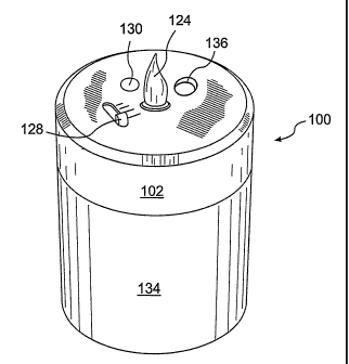
inch and
approximately three inches wide. The remainder of the device 300 is preferably
between
about two inches and about ten inches high and preferably between about one
and one-half
inches and about six inches wide. Thus configured, the device 300 can
substantially take on
the size and shape of various conventional candles, while the tip 324, by
encapsulating the
LEDs 306a, 306b, simulates a flame.
[0073] The chassis cover 302a also includes an emission aperture 336
therethrough. When
the chassis cover 302a is placed on the chassis base 302b, the emission
aperture 336 aligns
with the fragrance emitter 308. In particular, the emission aperture 336 is
formed such that a
fragrance dispensed by the fragrance emitter 308 passes through the chassis
cover 302a to the
ambient air, i.e., the chassis cover 302a does not impede the dissemination of
the fragrance
from the fragrance emitter 308.
[0074] The chassis cover 302a is preferably secured to the chassis base 302b,
although such
is not required. For example, as shown in Figure 8A, the chassis cover 302a
may be
removably attached to the chassis base 302b such that access to, for example,
the reservoir
326 andlor the batteries 318, may be gained for replacement purposes. When the
chassis
cover 302a is removably attachable to the chassis base 302b, a locking
mechanism may be
employed. For example, attractive magnets may be situated on the chassis cover
302a and
the chassis base 302b, or the chassis cover 302a may include a feature that is
designed for
compatibility with a mating feature of the chassis base 302b. In this manner,
only specific
covers and bases can be used.
[0075] In another aspect, we contemplate that the cliassis base 302b and the
chassis cover
302a, when secured together to form the unitary device 300, may be relatively
movable.
Specifically, when the chassis cover 302a is cylindrical, it may be rotatable
on the chassis
base 302b. For example, the rotation of the chassis cover 302a may turn on and
off the LEDs
306a,306b and/or the fragrance emitter 308.
-20-
CA 02555031 2006-08-01
WO 2005/074999 PCT/US2005/003290
[0076] As an alternative to the removable chassis cover 302a, when, for
example, a new
scent is desired or the reservoir 326 is empty, the device 300 may include a
hatchway for
purposes of replacing the reservoir 326. Examples of two contemplated
hatchways 338a,
338b are illustrated in Figures 9 and 10, respectively.
[0077] As shown in Figure 9, the hatchway 338a may be located on the side of
the device
300. The hatchway 338a is preferably hinged and is not completely removable
from the
device 300. As shown, the hatchway 338a may be opened to gain access to the
reservoir 326_
[0078] Alternatively, the hatchway 338b may be formed on the bottom of the
device 300.
For example, as shown in Figure 10, a substantially circular hatchway 338b is
removable
from the device 300. In this configuration, the reservoir 326 is preferably
coupled to the
hatchway 338b. By coupling the reservoir 326 thereto, the hatchway 338b
supports the
reservoir 326, and, when assembled, ensures appropriate positioning of the
wick 464 with
respect to the atomizer assembly 308. Specifically, when the hatchway 338b is
removed, the
wick 464 of the reservoir 326 is removed from contact with the atomizer
assembly 308. The
reservoir 326 is then removed from the hatchway 338b, a new reservoir 326 is
coupled to the
hatchway 338b, and the hatchway 338b is reattached, with the reservoir 326
properly aligning
with the atomizer assembly 308. When the hatchway 338b of Figure 10 is used,
it may be
unnecessary for the horizontal platform 342 to support and to align the
reservoir 326, as the
hatchway 338b will perform these functions. As such, the horizontal platform
342 will
support the atomizer assembly 308, either directly, or preferably, with the
wire-like support
466 discussed above.
[0079] The chassis base 302b may also include one or more apertures 340
through which
user control switches pass. A toggle switches 332, for example, allows a user
to turn on and
off one or more of the fragrance emitter 308 and the LEDs 306a, 306b, and a
slider switch
328 allows a user to adjust the rate at which fragrance is emitted from the
fragrance emitter
308. Alternatively or additionally, switches may also be provided that allow a
user to adjust
the light emission properties of the LEDs 306a, 306b, or to change an emitted
light show.
-21-
CA 02555031 2006-08-01
WO 2005/074999 PCT/US2005/003290
[0080] Thus, the third embodiment provides a still fiuther light and substance
emitting
device 300. As with first and second embodiments described above, the device
300 may be
configured to mimic the size and shape of a conventional candle.
[0081] As should thus be apparent, in each of the preferred embodiments, a
unitary housing
comprises a device that emits both a flickering light and a/substance, such as
a fragrance, to
the ambient air. As discussed above, in a preferred embodiment of our
invention, the device
is inserted into a holder. Much like typical replaceable votive candles would
be placed into
decorative holders, our invention also provides unique holders for use with
lighting devices
according to our invention.
[0082] Figure 5 shows the device 100 of the first embodiment in a holder 104.
Specifically,
the holder 104 has a globe-like shape, with a bottom, and an open top, similar
to a
conventional holder for a votive candle. The unitary housing comprising the
combination of
the chassis 102 and the base 134 is placed inside the holder 104, through the
open top of the
holder 104. Preferably, at least a portion of the holder 104 allows light to
be emitted
therethrough. Figures 11 and 12A-12D show some representative alternative
holder 304
configurations into which a light and fragrance emitting device 300 can be
placed. These
examples are by no means limiting.
[0083] When a fragrance emitter is used, the emitted fragrance should also be
emitted from
the holder, and it is thus preferred that the holder provide ample
ventilation. In particular, the
light and fragrance emitting device is preferably arranged in the holder such
that the emission
aperture through which the fragrance is dispensed is between about one inch
(25.4 mm) and
about six inches (152.4 mm) from the top of the holder and substantially away
from the inner
surface of the holder. More preferably, the emissive aperture is between
substantially flush
with and about five inches (127.0 mm) from the top of the holder. With such an
arrangement,
buildup of fragrance on the inside of the holder is min;mized. Moreover, the
holder may be
designed to aid the flow of the fragrance to the ambient environment. By
tapering the holder
such that the width of the holder narrows nearer the top of the holder,
airflow will increase as
it leaves the holder. Furthermore, we prefer that the holder not impede the
emission of light
from the LEDs. Specifically, the unitary housing is preferably arranged in the
holder such
that the tip (as used in the first and third embodiments, discussed above) is
between about
-22-
CA 02555031 2006-08-01
WO 2005/074999 PCT/US2005/003290
one-half of one inch (12.7 mm) and about two inches (50.8 mm) from the holder,
and
preferably closer than one inch (25.4). The holder may also act as a diffuser.
Furthermore,
we envision that the holder could fiirther include, for example, a fan for
aiding in further
dispersion of the fragrance emitted from the fragrance emitter.
[0084] The holder may comprise a single piece into which the housing is
placed.
Alternatively, as shown in Figures 12A-12D, a holder 304 may also comprise a
holder base
304a and a holder cover 304b. More specifically, the device is contained
within, or
alternatively comprises, the holder base 304a that receives and supports the
holder cover
304b. The holder cover 304b, when supported by the holder base 304a, covers
the tip 324.
That is, light emitted from the housing by the respective illumination devices
also passes
through the holder cover 304b. Alternatively, the housing, e.g. the top 324,
may not diffuse
emitted light, and only the holder cover 304b diffuses emitted light.
[0085] As a specific example of this embodiment, as shown in Figure 12A, a
holder base
304a containing a unitary device as described above in the preferred
embodiments has a
circumferential lip 304c extending radially outwardly from the holder base
304a. At least a
lower portion 304d of the holder cover 304b is sized so as to engage the lip
304c of the
holder base 304a, thereby resting the holder cover 304b on the holder base
304a. Other
illustrative examples of holders 304 are shown in Figures 12B-12D.
[0086] While we envision that the holder cover 304b may rest on the holder
base 304a, it is
preferable that the holder cover 304b detachably attach to the holder base
304a. For example,
the holder cover 304b may be designed to snap onto the holder base 304a.
Alternatively, the
holder cover 304b and the holder base 304a may be designed such that the
holder cover 304b
is rotated onto the holder base 304a, forming a loclcing engagement. In this
or any
configuration, the holder cover 304b may be relatively movable when secured to
the holder
base 304a. Specifically, when the holder cover 304b is generally cylindrical,
it may be
rotatable on the holder base 304a to turn the LEDs 306a, 306b and/or the
fragrance emitter
308 on and off. Additionally, the engagement and disengagement of the holder
cover 304b
and the holder base 304a may act to turn the light source and/or substance
emitter on and off.
In this inanner, the device would only operate with the holder cover 304b
attached.
Moreover, the holder cover 304b and holder base 304a may be specially designed
such that
-23-
CA 02555031 2006-08-01
WO 2005/074999 PCT/US2005/003290
only certain covers 304b can be used with the holder base 304a. For instance,
the holder base
304a may include a reader (not shown) that reads an ID (e.g., an RF tag) of
the holder cover
304b. In this manner, the device will not work unless the holder cover 304b
has an
appropriate ID.
[0087] When using the holder 304 according to this embodiment, we also
envision that the
holder cover 304b could emit a fragrance therefrom. For example, impregnable
materials
such as polyolefins are known that may be impregnated or infused with a
fragrance. By
forming the holder cover 304b of such a material, the holder cover 304b will
emit a fragrance
over time in addition to that emitted by the fragrance emitter 308.
Alternatively, the device
of this embodiment could not include the fragrance emitter 308, in which case,
only the
holder cover 304b will emit a fragrance. Also, with respect to the second
embodiment
described above, we note that the combination of chassis and base resembles a
decorative
candle, in which case a holder may not be desired. In such a case the base or
chassis may be
impregnated with a fragrance.
[0088] Because the holder cover 304b of this embodiment is removable, access
to the
device is facilitated (for example, to turn the LEDs 306a, 306b, on or off)
and the holder
cover 304b can be easily, replaced. For example, when the fragrance
impregnated in the
holder cover 304b is completely disseminated, a fresh, new holder cover 304b
can easily be
purchased and attached. Also, a user that has recently redecorated, or that
wants to move the
device to another room, may purchase a holder cover 304b having a certain
color or other
aesthetic feature. Moreover, replacement holder covers 304b may provide
different smells.
In other embodiments, the entire holder (or base) may be replaced.
[0089] While several preferred embodiments have been set forth above, many
different
embodiments may be constructed without departing from the spirit and scope of
our
invention. Our invention is not limited to the specific embodiments described
above. To the
contrary, our invention is intended to cover various modifications and
equivalent
arrangements included within the spirit and scope of our invention as defined
by the claims.
The claims are to be accorded the broadest scope, so as to encompass all such
modifications,
equivalent structures, and functions.
-24-
CA 02555031 2006-08-01
WO 2005/074999 PCT/US2005/003290
INDUSTRIAL APPLICABILITY
[0090] Our invention provides a device for light and/or fragrance emission.
The device
provides an overall desired aesthetic ambience in an area, such as a room.
-25-