Note: Descriptions are shown in the official language in which they were submitted.
CA 02556228 2012-10-17
1
METHODS FOR REDUCING HOLLOW ORGAN VOLUME
Background of the Invention
1. Field of the Invention:
The present invention pertains to medical equipment and more particularly to
mechanical methods for reducing the volume of the stomach for the treatment of
obesity.
2. General Background and State of the Art:
Approximately 64% of Americans are overweight and obesity is rapidly becoming
an epidemic resulting in a multitude of co-morbidities (e.g. cardiovascular
disease, diabetes,
etc.) and enormous medical costs. Approximately $75 billion dollars are spent
each year on
weight-related diseases in the US alone.
Historically, methods of weight reduction have ranged from oral
pharmacological
means, a multitude of diets, and various exercise programs. These approaches
have
generally =resulted in temporary weight loss, with no or limited long-term
benefit.
In recent years, the concept of obesity being a disease has gained momentum.
To that
end, surgical treatments have been developed to provide a more permanent
solution (e.g.
stomach stapling, gastric bypass, and the like). However, these treatments are
generally
surgical in nature, which imply inherent risk and high cost to the patient.
Thus, it remains desirable to develop new alternatives to provide non-invasive
or
minimally-invasive solutions to obesity.
Summary Of The Invention
The present invention overcomes some or all of the shortcomings of the current
techniques by providing a minimally-invasive placement of a mechanical
structure for
reducing the volume of the stomach via an esophageal approach.
One embodiment involves esophageal delivery of a series of anchors into the
stomach wall. The anchors are connected with a tensioning member (e.g.
suture), which is
CA 02556228 2006-08-11
WO 2005/079673 PCT/US2005/004692
2
subsequently tensioned to cinch the anchors together, resulting in a stricture
(or stoma) and
reduction in stomach volume. Once the desired size-reduction is achieved, the
delivery
device secures the tensioning member and disconnects it. The delivery system
is designed
to hold multiple anchors, which are placed around a circumference of the
stomach using
endoscopic guidance. In one embodiment, a standard endoscope is attached to
the delivery
system, but an endoscope may also be integrated into the delivery system. In
an
alternative embodiment, the delivery system is compatible with the working
lumen of a
standard endoscope. The anchors may be constructed from stainless steel, shape-
memory
alloys, or various polymers and are attached to the stomach wall via sutures,
various
crimping techniques (e.g. staples), rivets, grommets, or the like and have
eyelets through
which the tensioning member is strung. The first anchor may be fixedly
attached to the
tensioning member and the others may be free floating on the tensioning
member. The
tensioning member is sufficiently flexible to allow for cinching the anchors
together and is
constructed from a high-tensile, corrosion-resistant material (e.g. Kevlar
fiber, braid or
cable; stainless steel wire, braid or cable). The above procedure may be
performed more
than once to create multiple strictures and achieve the desired volume
reduction.
An alternative embodiment involves esophageal delivery of a tensioning member,
which is a suture or the like stitched to the stomach wall in a
circumferential manner.
Multiple stitches are placed under endoscopic guidance (integral or non-
integral) to define
a circumference and a cinching device is utilized to apply tension the
tensioning member,
resulting in a volume reduction. As used herein, integral means formed
together as a unit,
and non-integral means functioning as separate units. The cinching device is
then used to
secure the tensioning member (e.g. a knot) and disconnect it. This procedure
may also be
performed more than one to create multiple strictures in the stomach.
In another embodiment, the delivery system deploys the anchors and tensioning
member, and a subsequent device is utilized to tension (i.e., cinch), secure,
and terminate
the tensioning member.
A calibration mechanism may also be designed into the system to control the
size
of the stricture to be created. The mechanism may take the form of a non-
compliant or
semi-compliant balloon, which may be inflated to a desired diameter. The
mechanism
may also be comprised of a mechanically-expanding device. The calibration
mechanism
may also be simply a semi-rigid rod or tube, and the delivery system itself
may act as the
calibration member. The tensioning member may then be tensioned until it
contacts the
CA 02556228 2012-10-17
3
calibration device, and then the tensioning member may be secured and
terminated as
described above.
It may also be desirable to adjust the size of the stricture post-procedure.
The
preferred method for adjusting the stricture size could be to allow for the
termination of the
tensioning member (e. g. suture) to be mechanical in nature (rather than a
knot) and allow
for additional suture to be available for loosening the stricture. The suture
could be on a
spool or other system such that the suture could also be tightened.
Alternatively, the original
tensioning member could be severed and removed, and an accessory device may be
provided to restring the anchors back together to achieve an alternative
constriction in the
stomach.
Multiple devices may be used to optimally place these anchors and tensioning
member, apply tension to cinch the stomach wall together, secure the
tensioning member,
terminate the tensioning member, and visualize the procedure.
An alternative device for reducing stomach volume is a diaphragm deployed
within a
region of the stomach to divide the stomach into smaller sections. In one
embodiment the
diaphragm is placed in a near-vertical orientation to the esophagus and
extends
(approximately) perpendicularly to the esophagus until it contacts the distal
portion of the
stomach. Alternatively, the diaphragm could be placed nearly perpendicularly
to the
esophagus or at an angle, such that the food passageway cross-sectional area
is reduced over
a discrete length. These diaphragms would be anchored to the stomach wall via
previously-
described anchoring techniques, and a tensioning mechanism is provided to
tighten or stiffen
the diaphragm to create a wall.
Another method for reducing stomach volume is to attach a series of anchors to
the
stomach wall using adhesive. The anchors have one or more eyelets, through
which a
tensioning member is strung. Once the anchors are fixed to the stomach wall,
the tensioning
member is tensioned and constrained. In this manner, the wall of the stomach
is not
punctured or otherwise damaged and a large anchor surface area may be
achieved. The
adhesive may be incorporated into the anchor itself or applied via a delivery
system. The
anchors may also be adhered between two folds of tissue, such that the anchor
is sandwiched
between the tissue. This may create a more durable bond and may promote tissue
in-growth.
CA 02556228 2013-10-10
3a
Accordingly, there is provided a system for reducing the volume of a stomach
cavity,
comprising: a tubular member having a proximal end and a distal end; a tissue
acquisition
and fixation device disposed at the distal end of the tubular member, the
tissue acquisition
and fixation device including first and second members movable from an open
configuration
to a closed configuration to substantially simultaneously create first and
second folds of
tissue; a pledget removably disposed between the first and second members of
the tissue
acquisition and fixation device, such that the pledget is configured to be
positioned between
the first and second folds of tissue created by the tissue acquisition and
fixation device, the
pledget including an elongate, flexible tether having one end attached to the
pledget and a
free end extending therefrom that is configured to be tensioned to manipulate
tissue to which
the pledget is attached; and an anchor housed within the first member of the
tissue
acquisition and fixation device, and the anchor being adapted to secure the
pledget between
the first and second folds of tissue when the tissue acquisition and fixation
device moves
from the open to the closed configuration.
Brief Description of the Drawings
FIG. 1 depicts a staple.
CA 02556228 2006-08-11
WO 2005/079673
PCT/US2005/004692
4
FIGS. 2a and 2b depict the staple of FIG. 1 attached to the stomach wall.
FIGS. 3a and 3b depict a rivet.
FIGS. 4a and 4b depict the rivet of FIGS. 3a and 3b attached to the stomach
wall.
FIGS. 5a and 5b depict another embodiment of a rivet.
FIGS. 6a and 6b depict the rivet of FIGS. 5a and 5b attached to the stomach
wall.
FIG. 7 depicts an anchor.
FIG. 8 depicts the anchor of FIG. 7 sutured to the stomach wall.
FIG. 9a and 9b depict the anchor of FIG. 7 attached to a flexible material.
FIG. 10 depicts partial view of a plurality of anchors attached to the stomach
wall
and an un-tensioned tensioning member attached to the anchors.
FIG. 10a depicts schematic view of a plurality of anchors attached to the
stomach
wall.
FIG. 11 depicts a partial view of the anchors attached to the stomach wall of
FIG.
10 with the tensioning member tensioned to cinch the anchors together.
FIG. 1 la depicts a schematic view of the anchors being cinched together by
tensioning the tensioning member.
FIG. 12 depicts a cross-sectional view of a clip.
FIG. 12a depicts a cross-sectional view of an adjustable clip.
FIG. 13 depicts a cross-sectional view of the stomach cavity with a suture
sewn
around the stomach wall.
FIG. 13a depicts a schematic view of a stomach cavity with a suture sewn
around
the stomach wall.
FIG. 14 depicts a schematic view of the stomach cavity of FIG. 13a, with the
suture
tensioned to form a stricture within the stomach cavity.
FIG. 15a depicts a schematic view of a stomach cavity with a tensioning member
secured to the inner stomach wall.
FIG. 15b depicts a schematic view of the tensioning member of FIG. 15a forming
a
stricture within the stomach cavity.
FIG. 16a depicts a schematic view of a stomach cavity with a first and a
second
tensioning member secured to the inner stomach wall.
FIG. 16b depicts a schematic view of the first and second tensioning members
of
FIG. 16a forming a fist and a second stricture within the stomach cavity.
FIG. 17a depicts a schematic view of a stomach cavity with a tensioning member
secured to the inner stomach wall in a spiral configuration.
CA 02556228 2006-08-11
WO 2005/079673 PCT/US2005/004692
FIG. 17b depicts a schematic view of the tensioning member of FIG. 17a forming
a
spiral stricture within the stomach cavity.
FIG. 18a depicts a schematic view of a balloon inflated in the stomach cavity
with
a tensioning member anchored to the inner stomach wall
5 FIG. 18b depicts a cross-sectional view taken along line 18b-18b of FIG.
18a.
FIG. 19a depicts a schematic view of the tensioning member of FIG. 18a
tensioned
around the inflated balloon.
FIG. 19b depicts a cross-sectional view taken along line 19b-19b of FIG. 19a.
FIG. 20 depicts a device for securing staples to the stomach wall.
FIG. 21 depicts a distal end of a device being actuated with a sheath.
FIG. 22 depicts another embodiment of the device shown in FIG. 20.
FIG. 23a depicts an anchor piercing the stomach wall.
FIGS. 23b and 23c depict the anchor of FIG. 23a in a locked configuration.
FIGS. 24a through 24f depict embodiments of a hook anchor.
FIG. 25 depicts another embodiment of an anchor.
FIG. 26 depicts yet another embodiment of an anchor.
FIGS. 27a through 27c depict varying sizes of the anchor of FIG. 26 attached
to the
stomach wall.
FIGS. 28 and 29 depicts another embodiment of an anchor.
FIGS. 30 through 32 depict a device for securing anchors to the stomach wall.
FIGS. 33 through 35 depict a another device for securing anchors to the
stomach
wall.
FIG. 36 depicts yet another device for securing anchors to the stomach wall.
FIGS. 37 through 39 depicts a further embodiment of a device for securing
anchors
to the stomach wall.
FIGS. 40a through 4 Oc d epict a device delivering a three bard hook anchor
into
tissue.
FIGS. 41 and 42 depict another embodiment of a device for delivering anchors
to
tissue.
FIGS. 43 through 46 depict the device of FIGS. 41 and 42 delivering a staple
to the
stomach tissue.
FIG. 47 depicts an alternative embodiment of the delivery device shown in
FIGS.
41 and 42.
CA 02556228 2006-08-11
WO 2005/079673 PCT/US2005/004692
6
FIG. 48 depicts another alternative embodiment of the delivery device shown in
FIGS. 41 and 42.
FIG. 49 depicts a delivery device for delivering rivets to tissue.
FIGS. 50 and 51 depict a schematic view of a diaphragm positioned within the
stomach cavity.
FIG. 52 depicts the diaphragm shown in FIG. 50.
FIG. 53 depicts a schematic view of anchors adhered to the stomach wall.
,
FIGS. 54 through 56 depict an anchor attached to a stomach wall with an
adhesive.
FIGS. 57 and 58 depict a device for delivering the anchors of FIGS. 54 through
56.
FIG. 59 depicts another embodiment of a device for delivering the anchors of
FIGS. 54 through 56.
FIG. 60 depicts another embodiment of an anchor.
FIGS. 61 and 62 depict a device for delivering the anchor shown in FIG. 60.
FIG. 63 depicts a schematic view of anchors forming a stricture within the
stomach
cavity.
FIGS. 64 and 65 depict another embodiment of a device for delivering the
anchor
shown in FIG. 60.
FIG. 66 depicts a first tensioning member secured in the stomach cavity near
the
GEJ and a second tensioning member secured in the stomach cavity near the
pylorus.
FIG. 67 depicts a first stricture formed near the GEJ and a second stricture
formed
near the pylorus.
FIG. 68 depicts another device for delivering anchors to a fold of tissue.
FIG. 68a depicts an alternative embodiment of the device depicted in FIG. 68.
FIG. 69 depicts yet another device for delivering anchors to a fold of tissue.
FIG. 69a depicts an alternative embodiment of the device depicted in FIG. 69.
FIG. 70 depicts another alternative embodiment of the device depicted in FIG.
69.
FIG. 71 depicts a schematic view of longitudinal plications disposed in the
stomach
cavity.
FIG. 72 depicts a cross-sectional view taken along line 72-72 of FIG. 71,
wherein
the plications are single folds.
FIG. 72a depicts a cross-sectional view of the stomach cavity wherein
plications
are dual folds.
FIG. 73 depicts a pledget.
CA 02556228 2006-08-11
WO 2005/079673 PCT/US2005/004692
7
FIG. 74 depicts a schematic view of a stricture created by cinching together
plications within the stomach cavity, depicting both radial and longitudinally
placed
plications.
FIG. 75 depicts a cross-sectional view taken along line 75-75 of FIG. 74.
FIG. 76 depicts a cross-sectional view of the stomach cavity where plications
are
cinched together with staples.
FIG. 77 depicts a schematic view of a stomach cavity w ith three fastening
lines
creating lumens within the stomach.
FIG. 78 depicts a cross-sectional view taken along line 78-78 in FIG. 77.
FIG. 79 depicts a schematic view of the stomach cavity shown in FIG. 77
wherein
the fastening lines have been cinched together.
FIG. 80 depicts a cross-sectional view taken along line 80-80 of FIG. 79.
FIG. 81 depicts a cross-sectional view of a stomach cavity with three
fastening
lines.
FIG. 82 depicts a cross-sectional view of the stomach cavity shown in FIG. 81
wherein the fastening lines are cinched together.
Detailed Description of the Preferred Embodiments
As will be discussed in detail below, a method of reducing the volume of the
stomach i nvolves c reating s trictures o r s tomas w ithin the s tomach c
avity. T hese
strictures can be created through minimally-invasive placement of a mechanical
structure for reducing the volume of the stomach via an esophageal approach.
For
ease of reference, the following embodiments will be described as being
advanced
transorally to the stomach, although the embodiments of the restricting
devices can
be used within other hollow body organs as well.
One embodiment for reducing the volume of the stomach cavity includes placing
anchors along the stomach lining in a desired pattern, and then cinching the
anchors
together with a tensioning member, such as a suture or wire. FIGS. 1 - 2b show
an
embodiment of an anchor 40 that may be used in the trans-esophageal or trans-
oral
procedure. The anchor in this embodiment is a staple 42 having an eyelet 44
and arms 46,
each with a sharp tip 48. FIG. 1 shows the staple in an open configuration
with the arms
being relatively straight and parallel to one another. In use, the staple is
delivered to the
stomach cavity in the open configuration and then stapled so that the staple
is attached to
the stomach wall SW in a closed configuration as shown in FIGS. 2a and 2b. In
the closed
CA 02556228 2006-08-11
WO 2005/079673
PCT/US2005/004692
8
configuration the arms of the staple are bent towards one another, each being
formed into a
hook-like shape. The staple may or may not puncture through all layers of the
stomach
wall. FIG. 2a depicts the staple attached to the stomach wall so that the arms
of the staple
have not punctured through the stomach wall and the eyelet of the staple
positioned along
the inner stomach wall within the stomach cavity SC. FIG. 2b shows the staple
attached to
the stomach wall with the arms of the staple having punctured through all
layers the
stomach wall.
Another embodiment of the anchor 40 is shown in FIGS. 3a through 4b. Referring
to FIG. 3a, the anchor is a rivet 50 having a male portion 52 and a female
portion 54. The
male portion includes a first end 56 having a flange 58, and a second end 60
having a barb
62, although in other embodiments the second end may only include a post. The
female
portion of the rivet includes a tubular body 63 having first end 64 with an
open bore 66,
and a second end 68 having a flange 70 and an eyelet 72. FIG. 3b shows one
embodiment
of the rivet with the male portion mated with the female portion, and in this
embodiment
the rivet is generally straight. In another embodiment, the male and female
portions are
curved as shown in FIG. 3c. The rivet is delivered to the stomach cavity in an
open
configuration, as shown in FIG. 3a, wherein the male and female portions are
not attached
to one another. Once in a desired position along the inner stomach wall SW,
the rivet is
transformed into a closed configuration by inserting the second end of the
male portion
into the open bore of the female portion. To insert the rivet into or through
the stomach
wall, a portion of the stomach wall may need to be gathered to form a fold F.
The stomach
tissue may be gathered by a vacuum or with a mechanical device such as with
graspers or
forceps. As shown in FIG. 4a, the rivet may be inserted into the stomach wall
without
puncturing through all of the layers of the wall, or in another embodiment,
the rivet may be
inserted through the stomach wall as shown in FIG. 4b. In both embodiments,
the eyelet
of the rivet is positioned within the stomach cavity. It should be noted that
the flanges 58
and 70 provide increased surface area to contact the stomach wall, and
therefore the rivet is
less likely to detach.
Yet another embodiment of the anchor 40 is shown in FIGS. 5a through 6b. A
rivet 74 similar to rivet 50 is shown, and therefore like reference numerals
will correspond
to like or similar details of the rivet. The rivet 74 does not include an
eyelet, and instead,
the rivet 74 includes a through-hole 76 that extends through the male portion
52 and the
female portion 54. Once the rivet 74 is positioned within or through the
stomach wall SW
CA 02556228 2006-08-11
WO 2005/079673 PCT/US2005/004692
9
as shown in either FIGS. 6a or 6b, a tensioning member, such as a suture or
wire, can be
threaded through the through-hole of the rivet.
Another embodiment of the anchor 40 is shown in FIGS. 7 and 8. In this
embodiment, an anchor 80 includes a base 82, an eyelet 84 disposed on the
base, and at
least two through-holes 86 located on opposite sides of the eyelet. In use,
the anchor is
delivered to the stomach cavity SC and the base of the anchor is placed
against the
stomach wall SW. Sutures are then threaded through the through-holes and into
the
stomach wall to attach the anchor as shown in FIG. 8. Multiple anchors may be
placed
along the stomach wall in a desired pattern, and then a tensioning member
threaded
through the eyelets of the anchors can be tightened to cinch the anchors
together, reducing
the volume of the stomach cavity.
All of the anchors disclosed herein can be constructed from titanium,
stainless
steel, shape-memory alloys, such as nitinol, other biocompatible metal alloys,
or various
polymers.
A flexible member 8 8 may also be used when suturing anchors 80 to the stomach
wall SW as shown in FIGS. 9a and 9b to help secure the anchor to the stomach
wall by
reducing any stress between the anchor and the stomach lining. FIG. 9 shows
the surface
area of the flexible member being greater than the surface area of the base.
Although the
flexible member is shown to be round in shape, other shapes, such as oval,
square,
rectangle, or any polygonal shape may be used. The flexible member may be made
from a
mesh, or a biocompatible polymer matrix, polyester, nylon, PTFE, c ollagen
matrix, and
may further include a metal material formed within or around the mesh to
promote healing.
When delivering the anchor and the flexible member to the stomach cavity, the
flexible
member may be integrated with the anchor, pre-attached to the anchor with a
suture, or the
base of the anchor may b e joined to the flexible member with an adhesive. In
another
embodiment, the flexible member and anchor are delivered separately to the
stomach
cavity. FIG. 9b shows the anchor and flexible member secured to the stomach
wall with
two sutures placed through the through-holes 86 and the flexible member into
the stomach
wall. The flexible member will provide increased surface area to reduce the
stress applied
to the stomach lining, and if the flexible member is formed of a mesh or mesh-
like
material, the flexible member could also increase tissue in-growth and/or
scarring,
resulting in a stronger, more durable attachment. It has also been
contemplated that the
flexible member could be reinforced , i.e., attached to the stomach tissue via
various
adhesives.
CA 02556228 2006-08-11
WO 2005/079673 PCT/US2005/004692
There are other methods that could also be performed to reduce the stress
applied
to the stomach wall and to prevent erosion of the tissue/anchor interface. To
reduce stress,
the number of anchors 40 used in the procedure could be increased. The minimum
number
of anchors that could be used in this type of procedure would be two, and the
maximum
5 number of anchors would be determined by the size of the stomach cavity
and the size of
the anchor. Also, the "bite" size could also be increased. The tetra "bite"
refers to the
amount of tissue gathered or acquired by the anchor to secure itself to the
stomach wall.
The depth of the "bite" can also be increased to the point of exiting the wall
of the
stomach. In another embodiment, a flange and/or other stress-reducing element,
such as a
10 washer, could be placed on the exterior wall of the stomach. All of
these examples would
be helpful in reducing the stress on the stomach wall and preventing
detachment of the
anchor.
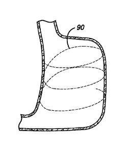
In use, multiple anchors 40 are secured around a portion of the stomach cavity
SC
where the placement of a stricture is desired. The anchors are placed by
various devices
that will be discussed more below. A partial cross-sectional view of the
stomach is shown
in FIG. 10 with several anchors attached to the stomach wall. This figure
shows the
anchors 80 sutured to the stomach wall, although any of the anchors 40,
including the
staple 42 and the rivets 50 and 74, could be shown because all are used in a
similar
manner. A tensioning member 90, such as a suture, wire, or zip tie, connects
the anchors
together by being strung through the eyelets 84 of each anchor. In a case
where the rivet
74 is used, the tensioning member would be strung through the through holes 76
of the
rivet. The tensioning member may be pre-strung through the eyelets or through-
holes of
the anchors before each anchor is attached to the stomach wall. FIG. 10a
schematically
illustrates the entire stomach before the anchors are cinched together. In one
embodiment
the first anchor to be attached to the stomach wall may be fixedly attached to
the
tensioning member and the other anchors may be free floating on the tensioning
member.
After the final anchor is attached, the free end of the tensioning member
would be pulled
proximally (towards the esophagus) to cinch the anchors and then tied off to
the first
anchor to secure the tensioning member. In another embodiment shown in FIG.
10a, all of
the anchors are free floating on the tensioning member, so that after all of
the anchors have
been secured around the stomach wall, there are two free ends 92 of the
tensioning
member that are held together by a clip 94. A cross section of the clip is
shown in FIG. 12,
the clip is formed of a relatively thin metal, such as stainless steel,
carbon, NiTi, tantalum,
or other biocompatible metal and includes two lumens 96 that will house the
free ends of
CA 02556228 2006-08-11
WO 2005/079673 PCT/US2005/004692
11
the tensioning member. One lumen would also be sufficient. To form a stricture
by
cinching the anchors together, a clamping device 98 having a pair of clamps or
pinchers
100 is used to hold the clip in p lace while the free ends o f t he tensioning
member are
pulled proximally. Pulling the tensioning member produces a stricture within
the stomach,
as shown in FIGS. 11 and 11 a. Once a desired tension is achieved producing a
stricture of
a desired size, the pinchers of the clamping device are activated to crush the
clip, thereby
closing the lumens of the clip to secure the free ends of the tensioning
member. The
tensioning member is then cut at a position proximal to the clip, leaving a
stricture within
the stomach cavity.
The tensioning member 90 should be sufficiently flexible to allow for cinching
the
anchors together. The tensioning member may be formed from a high-tensil,
corrosion-
resistant material, e.g., Kevlar fiber, braid or cable; stainless steel wire,
braid or cable;
polypropylene or other suture materials; or nitinol wire, braid, or cable.
Referring now to FIGS. 13 through 14, another embodiment is shown for reducing
the volume of the stomach cavity Sc. In this embodiment, a device is delivered
down the
esophagus to the stomach cavity, to allow for in-situ "purse-string" suturing
in the
stomach. Suturing devices are known in the art, such as the auto-suturing
devices from US
Surgical. S utures 1 02 are used to form a series o f "b ites" 1 04 around a
portion o f the
stomach and an internal mechanism is used to pull or cinch the sutures to the
desired
tension. The suture is then tied off, resulting in a reduction in volume in
the stomach
cavity. The suture material may include Kevlar, stainless steel wire or cable,
nitinol wire
or cable, braided Kevlar, and other corrosion-resistant materials. The length
of the suture
material is such that after an appropriate number of sutures have been
applied, two free
ends 106 are left in the stomach cavity. In one embodiment, the clip 94 is
slid onto the
free ends of the suture as shown in FIGS. 13 and 13a. To cinch the sutures,
the free ends
are pulled proximally with a grasping device 110, while the pinchers 100 of
the clamping
device 98 are used to hold the clip in a fixed position. Once the desired
tension is reached,
as shown in FIG. 14, the pinchers of the clamping device are activated to
crush the clip,
thereby securing the free ends of the suture. The clamping device and grasping
device are
removed from the stomach cavity, leaving a stricture that reduces the volume
of the
stomach cavity. It has also been contemplated that the free ends of the suture
may be tied
together in a knot.
The strictures formed using the tensioning member 90 with anchors 40 or the
suture 102 alone could be adjusted for any reason at any time. In one
embodiment, and
CA 02556228 2006-08-11
WO 2005/079673 PCT/US2005/004692
12
under endoscopic guidance, the tensioning member or suture could be cut,
releasing the
stricture. A new tensioning member could then be threaded through the eyelets
of the
anchors 40 or a new suture threaded along the stomach wall, and then tensioned
to form a
stricture of the desired size. The old tensioning member or suture and clip 94
would have
In another embodiment, the clip could be an adjustable clip 94a, such as the
clip
disclosed in FIG. 12a. Using the adjustable clip, the tensioning member could
be adjusted
The strictures produced by the anchors 40 and the sutures 102 may be
positioned
anywhere w ithin t he s tomach c avity S C b etween t he g astroesophageal j
unction ( "GEJ")
and the pylorus, and any number of strictures may be produced to reduce the
volume of the
CA 02556228 2006-08-11
WO 2005/079673 PCT/US2005/004692
13
112 is formed as shown in FIG. 15b. The volume of the stomach cavity is
reduced, and a
reservoir R. is formed above the stricture in the stomach cavity.
The length of the stomach cavity SC may be effected by placing multiple
strictures
within the stomach cavity or by placing a single stricture in a given
geometry, such as a
spiral. FIG. 16a schematically shows a first tensioning member 90a and a
second
tensioning member 90b positioned within the stomach cavity, being held with
anchors or
sutured to the stomach wall. After tightening the tensioning members to a
desired
diameter, two strictures 112a and 112b are formed as shown in FIG. 16b. The
placement
of the second stricture further reduces the volume of the stomach cavity.
Tensioning
members can be tensioned so that the first stricture has a smaller, larger, or
the same cross-
sectional area as the second stricture. As mentioned, a single stricture can
also be used to
affect the length of the stomach cavity. FIG. 17a shows a tensioning member 90
spiraled
around the stomach cavity, either with anchors or sutured itself. After the
tensioning
member is tightened to a desired tension, a spiral stricture 112c is formed as
shown in
FIG. 17b. The spiral configuration may be altered so that the inlet is larger
or smaller than
the outlet. Also, the tensioning member can be adjusted so that the cross-
sectional area of
the spiral stricture is variable or generally equal long the length of the
stomach cavity.
As previously described, the tensioning member 90 or suture 102 is tensioned
or
pulled proximally to cinch the anchors 40 or suture in order to form the
stricture within the
stomach cavity SC. In one embodiment, a calibration device 120 may be used to
control
the cross-sectional area of the stricture. The calibration device which may
include an
inflatable balloon 122 (or other inflatable or expanding device) attached to
the distal end of
a catheter 124. Once the anchors 40 are secured to the stomach wall SW, the
calibration
device is delivered to the stomach cavity and the balloon is placed in the
area of the
stomach cavity to be constricted and is inflated to the desired size, as shown
in FIGS. 18a
and 18b (cross-sectional view). The calibration device would inherently be
adjustable for
physician control. The tensioning member is then tensioned until the stricture
112
conforms to the calibration device as shown in FIGS. 19a and 19b. The
tensioning
member is then terminated and the balloon is deflated and removed from the
stomach
cavity. Use of the calibration device is optional and physicians may prefer to
control the
size of the stricture themselves without the use of the calibration device.
Referring now to FIGS. 20 through 22, a tissue fixation or stapling device 130
for
placing staples 42 within the stomach cavity is shown. The stapling device
includes a
flexible elongated body 132 having a proximal end 134 and a distal end 136. In
one
CA 02556228 2006-08-11
WO 2005/079673 PCT/US2005/004692
14
embodiment, the elongated body can be articulated, much like an endoscope. The
proximal end includes a handle 138 for maneuvering and activating jaws 140a
and 140b of
a fixation portion 142. A cartridge of staples can be loaded into jaw 140a of
the fixation
portion, and in one embodiment, the loaded staples may be pre-strung with a
tensioning
member 90. In the embodiment shown in FIG. 20, one end of the tensioning
member is
fixedly attached to the first staple housed in the fixation portion. The other
end of the
tensioning member is on a spool 144 located at the proximal end of the device
in the
handle. In another embodiment, the pre-strung tensioning member may not be
fixedly
attached to the first staple, but looped back inside the delivery device,
giving two free ends
to join together either by tying a knot or using the clip 94, which would be
located within
the fixation device. In either embodiment, the staples would be stacked
together in the
fixation device with the lead staple falling into the delivery mechanism for
crimping into
the stomach lining. A spring 146 can be located in jaw 140a to advance the
next staple
into the delivery mechanism. Once the fixation portion of the device is
located within the
stomach cavity and the distal end is positioned at the desired area for
fixation, a lever 148
located on the handle may be squeezed to actuate the jaws 140a and 140b of the
fixation
portion. Although not shown, the lever actuates the fixation portion using a
cable, pulley,
and hinges as would be known in the art. Similar to a conventional stapler,
the lead staple
is ejected from jaw 140a, through the stomach lining and jaw 140b, acting like
an anvil,
crimps the staple to the stomach lining. After the first staple is secured to
the stomach
wall, the next staple in s uccession is advanced by the spring into position
for ejection.
This process is repeated until all of the desired staples are secured to the
stomach wall. In
the embodiment where the tensioning member is fixed to the lead staple, a
separate device
may be used to cut the tensioning member from the spool, or a blade may be
incorporated
into the stapler device at the distal end to severe the tensioning member
after the staples
have been cinched together.
In another embodiment shown in FIG. 21, the fixation portion 142 of the
stapler
device 130 may be actuated using a sheath 150 that is moved distally over the
hinged jaws
140a and 140b, thereby actuating the fixation portion and securing a staple
into the
stomach wall. After a staple is fixed to the stomach wall, the sheath is
simply moved in
the proximal direction, away from the fixation portion, allowing the jaws 140a
and 140b to
reset. This process can then be repeated to secure additional staples around a
portion of
the stomach wall.
CA 02556228 2006-08-11
WO 2005/079673
PCT/US2005/004692
An additional embodiment of the distal end 136 of the stapler device 130 is
shown
in FIG. 22. In this embodiment, the distal end may swivel on a hinge so that
the fixation
portion 142 is generally perpendicular to the elongated body 132 of the
device. It may be
beneficial for the anchors to be placed at a angle to the axis of the delivery
system.
5 It
may also be advantageous to use a vacuum in conjunction with the delivery
device 130. The vacuum could be integrated into the device itself, or could be
a separate
tube positioned along the device. The vacuum would acquire a portion or "bite'
of the
stomach wall that could provide a solid foundation for fixing the anchor to
the tissue.
During the procedure for placing anchors along the stomach lining,
visualization is
10
important and may be accomplished by using an endoscope. In one embodiment,
the
endoscope connects to the delivery device, for example by a snap fit, so that
a standard
endoscope may be used. If the standard endoscope is steerable, the elongated
body of the
delivery device will be sufficiently flexible or articulated near the distal
end to allow for
the endoscope to position the anchors. In a situation where the endoscope is
not steerable,
15 the
delivery device will be articulated to allow for placement of the anchors. It
also has
been contemplated that fiber optics may be used to minimize the overall
profile of the
device.
An alternative anchor 180 is shown in FIGS. 23a through 23c. Anchor includes a
post 182 having a distal end 184 and a proximal end 186. The distal end
includes a sharp
tip 188 for piercing through the stomach tissue, and the proximal end includes
a flange 190
and an eyelet 192. In one embodiment, at least the post is formed of a shape
memory
alloy, such as nitinol, so that when the post is inserted into the stomach
tissue, a lock
portion 194 forms near the distal end of the post to secure the anchor into
the tissue. In
another embodiment, the lock portion is activated mechanically similar to a
molly-bolt. As
shown in FIG. 23c, the anchor may be fixed to the stomach wall by securing the
anchor
through a fold F in the stomach lining.
Yet more embodiments of anchors are shown in FIGS. 24a through 24c, and like
reference numerals are used for similar details. The anchors of this
embodiment are
similar to fish hooks. In FIG. 24a, a straight barb anchor 200 is shown,
having a post 202
with a distal end 204 and a proximal end 206. The distal end includes a barb
208 and the
proximal end includes an eyelet 210. FIG. 24b shows a dual barb hook 212
having two
hooks 214, each with a barb at its tip. A triple barb hook 216 is shown in
FIG. 24c, and
includes three hooks. Although not shown, another embodiment would be a single
barb
CA 02556228 2006-08-11
WO 2005/079673
PCT/US2005/004692
16
hook. These anchors could be made of a metal alloy such as stainless steel,
nitinol, or
other spring-like or superelastic material.
FIGS. 24d through 24f depict similar anchors to those shown in FIGS. 24a
through
24c, except that the anchors in FIGS. 24d through 24f include a flange 218 at
the proximal
end 206 of the post 202. Also, the anchors of FIGS. 24d through 24f include a
through-
hole 219 bored through the flange. A straight barb anchor 200a is shown in
FIG. 24d, a
dual barb hook 212a is shown in FIG. 24e, and a triple barb hook 21 6a is
shown in FIG.
24f.
Another embodiment of an anchor 220 is shown in FIG. 25. This anchor includes
a
post 222 having a distal end 224 and a proximal end 226. The distal end
includes a sharp
tip 228 and at least one barb 230 (two barbs are preferred) for piercing
through the
stomach tissue and securing to the stomach tissue. The proximal end includes a
flange 232
and an eyelet 234. Referring now to FIG. 26, another anchor 240 is shown
having a post
242 with a distal end 244 and a proximal end 246. Similar to anchor 220, the
distal end
includes a sharp tip 248 and at least one barb 250 (two barbs are preferred)
for piercing
through the stomach tissue and securing to the stomach tissue. The proximal
end includes
a flange 252 with a through hole 254 that runs perpendicular to the
longitudinal axis of the
flange. The posts 222 and 242 of these two anchors 220 and 250 can have
varying lengths
so that they pierce into the stomach tissue at a certain distance. FIGS. 27a
through 27c
show the anchor 250 having a post with varying lengths, and the anchor 220
would pierce
the stomach wall SW in a similar manner. FIG. 27a shows the anchor with a
relatively
short post so that the sharp tip and barbs are positioned within the stomach
wall. FIG. 27b
shows the anchor having a post that is slightly longer than the post shown in
FIG. 27a, so
that the sharp tip of the anchor is pierced through the stomach wall and the
barbs are
positioned within the stomach wall. As shown in FIG. 27c, a relatively longer
post
positions the sharp tip and the barbs on the exterior of the stomach wall.
Referring now to FIG. 28, another embodiment of an anchor 260 is shown. The
anchor has a generally tubular body 262 with a distal end 264 and a proximal
end 266.
The distal end includes a sharp tip 268 for piercing the stomach tissue, and
barbs 270 are
fashioned near the distal end. A through hole 272 is located near the proximal
end for
joining the anchor to the tensioning member. To manufacture this anchor, its
tubular body
may be cut from a tubing or stamped and rolled from a sheet. In use, the
anchor is pierced
into the stomach wall SW so that the barbs are located within the stomach wall
and the
through hole is located in the interior of the stomach cavity as shown in FIG.
29.
CA 02556228 2006-08-11
WO 2005/079673 PCT/US2005/004692
17
An embodiment of a delivery system 280 will now be discussed that delivers and
secures all of the anchors simultaneously to the stomach wall. Delivering all
of the
anchors simultaneously to the stomach is advantageous because it can provide
equal
spacing of the anchors, which will help provide an equal amount of stress on
each anchor.
Also, the time needed to complete the procedure would be reduced by delivering
the
anchors simultaneously. Referring to FIG. 30, the delivery system is shown to
include a
delivery sheath 2 82, which has a distal end 2 84 and a proximal end (not
shown). T he
delivery sheath houses at least two articulating members or delivery tubes 286
that include
a distal end 288 and a proximal end (not shown). The distal end of the
articulating
members are all attached to an atraumatic tip or nosecone 290, which may be
guide wire
compatible. An actuating rod 292 is connected to the nosecone and extends
through the
delivery sheath to the proximal end. As shown in the figures, the articulating
members
also include a proximal member 294 and a distal member 296, which remain
attached to
one another by a wire 298. Anchors and the tensioning member may be housed in
either
the proximal member or the distal member of the delivery tubes. However, it is
preferred
that the anchors be stored in the proximal member.
In use, the distal end of the delivery shaft 282 is positioned in the stomach
cavity
through the esophagus under endoscopic guidance, and initially the
articulating members
or delivery tubes 286 are collapsed within the delivery sheath. It is possible
that only the
nosecone 290 would be extending from the delivery sheath. Once the system is
within the
stomach cavity, the delivery sheath is pulled proximally while the delivery
tubes are held
in position, as shown in FIG. 30. Still fixing the position of the delivery
tubes, the
actuating rod is pulled proximally to expand the delivery tubes so that an
ejection end 300
of the proximal member comes into contact with the stomach wall SW as shown in
FIG.
31. A more detailed view of the ejection ends of the delivery tubes is shown_
in FIG. 32.
The anchors 240 are positioned inside the proximal member 294 at the ejection
end, and
the ejection ends of the proximal members include a slot 302 to allow the
anchors to be
strung together with the tensioning member 90. As best shown in FIG. 32,
plungers or
ejectors 3 04 are disposed w ithin t he p roximal m ember o f t he d elivery
tubes, and w hen
actuated they push the anchor into the stomach tissue.
All of the anchors in the delivery system 280 can be pre-strung together, and
in one
embodiment the tensioning member may be fixed to a first anchor, pass through
each
eyelet or through-hole and back through the eyelet of the first anchor, and
then up into the
delivery sheath 282 to the proximal end. After simultaneously ejecting all of
the anchors
CA 02556228 2006-08-11
WO 2005/079673 PCT/US2005/004692
18
from t he d elivery t ubes 286 i nto t he s tomach w all, t he d elivery t
ubes may b e r ernoved
from the stomach cavity, and the free end of the tensioning member may be
tightened at
the proximal end of the system to cinch all of the anchors together. Once
cinched, the free
end of the tensioning member can be secured by tying a knot or other
procedures, and then
the extra length of the tensioning member can be cut with a separate device. A
clip or
other slideable member can be advanced over the free end of the tensioning
member to a
desired position to maintain the stricture formed by the cinched anchors. In
another
embodiment, all of the anchors in the delivery system may ride freely on the
tensioning
member. In this configuration, the tensioning member would initiate in the
delivery
sheath, pass down the sheath and through the eyelets of each anchor, and up
into the
delivery shaft. The two free ends of the tensioning member could then be
clipped together
with the clip 94 and then tightened and secured as described above using the
clip.
In one embodiment, a vacuum may be applied to the entire stomach cavity
through
a separate vacuum tube to draw the tissue toward the delivery system 280 and
the ej ection
ends 300 of the delivery tubes 286 to facilitate placement of the anchors. It
has been
contemplated that the proximal ends of the delivery tubes could be attached to
a vacuum
source so that before ejecting the anchors, a vacuum can be created at the
ejection end of
the delivery tube to help in the placement of the anchors.
Another embodiment of a delivery system 320 is shown in FIGS. 33 and 34. The
delivery system includes a delivery sheath 322, which has a distal end 324 and
a proximal
end (not shown). The delivery sheath houses at least two articulating members
or delivery
tubes 326 that are flexibly or hingedly attached to a distal end 328 of a
central rod 330.
The delivery tubes each have an attached end 332 and an ejection end 334. At
the distal
end of the rod is an atraumatic tip such as a nosecone 336. The system also
includes a
pusher 338 attached to a hollow tube 340 that is disposed over the central
rod. Anchors
342 and the tensioning member 90 may be positioned at the ejection end of the
delivery
tubes as shown in FIG. 35, with the sharp tip 343 of the anchor located out of
the delivery.
In this embodiment the anchor 342 includes a through-hole 344 in its post 346.
In use, the distal end 324 of the delivery system 320 is delivered down the
esophagus to the stomach cavity. As the system is delivered, the plurality of
delivery tubes
286 are folded inside the delivery sheath 322 as shown in FIG. 33. Once in
position -within
the stomach cavity, the delivery sheath is pulled proximally while the central
rod is held in
position to release the delivery tubes. Next, the pusher 338 is pushed
distally until it
comes into contact with the attached ends 330 of the delivery tubes to expand
the delivery
CA 02556228 2006-08-11
WO 2005/079673
PCT/US2005/004692
19
tubes into an expanded configuration as shown in FIG. 34. The entire system
may then be
pulled proximally until sharp tips 343 of the anchors 342 engage the stomach
tissue. The
anchors are then simultaneously ejected from the delivery tubes and into the
stomach wall.
It is also possible for the anchors to be ejected o ne at a time. In one
embodiment, the
anchors are ejected by a pneumatic pressure. In this embodiment, the central
rod can
provide a pathway to direct air pressure to the delivery tubes to drive the
anchors into the
stomach tissue. In another embodiment, the anchors may be ejected by
triggering a
releasing spring in the delivery tubes. Still in another embodiment, the
anchors may be
held in the delivery tube by a quick release mechanism, such as a clip or a
magnet, and
once the anchor is seated in the stomach wall, the anchor is released. Also,
similar to the
above embodiment, a vacuum can be used to collapse the stomach cavity to
facilitate
placement of the anchors.
Yet another embodiment of a delivery system 350 is show in FIG. 36. In this
system, a delivery sheath 352, which has a distal end 354 and a proximal end
(not shown),
houses at least two distal articulating members or distal delivery tubes 356
that are flexibly
or hingedly attached to a distal end 358 of a central rod 360. The distal
delivery tubes each
have an attached end 362 and an ejection end 364. At the distal end of the
central rod is an
atraumatic tip such as a nosecone 366. The system also includes a pusher 368
attached to
a hollow tube 370 that is disposed over the central rod. In this embodiment,
at least two
proximal articulating member or proximal delivery tubes 372 are also housed
within the
delivery sheath. The proximal delivery tubes also include an ejection end 374.
In use, the distal end 354 of the delivery system 350 is delivered down the
esophagus to the stomach cavity. As the system is delivered, the plurality of
delivery tubes
356 and 372 are folded inside the delivery sheath 352. Once in position within
the
stomach cavity, the delivery sheath is pulled proximally while the central rod
is held in
position to release the proximal and distal delivery tubes. Next, the pusher
368 is pushed
distally until it comes into contact with the attached ends 330 of the distal
delivery tubes to
expand the distal delivery tubes into an expanded configuration. In one
embodiment the
proximal delivery tubes are self expanding. The central rod 360 may then be
pulled
proximally in order to pinch tissue of the stomach wall SW between the
proximal and
distal delivery tubes as shown in FIG. 36. A fold F of tissue may even be
created to place
the anchors through. The anchors are then ejected from the ends of the
delivery tubes and
into the stomach wall.
CA 02556228 2006-08-11
WO 2005/079673
PCT/US2005/004692
Many of the anchors described above can be ejected from the distal and
proximal
delivery tubes 356 and 372 of the delivery system 350. For instance, the male
portion 52
of rivet 50 can be loaded into one of the delivery tubes and the female
portion 54 of the
rivet can be housed in the other delivery tube. Therefore, when the distal
delivery tubes
5 are p ulled p roximally t o p inch s tomach t issue b etween t he p
roximal a nd d istal d elivery
tubes as shown in FIG. 36, the male and female portions of the rivet can be
ejected nearly
at the same time to mate the male portion with the female portion through the
fold of
stomach tissue. In another embodiment, the staples 42 could be loaded in one
of the
delivery tubes (either the proximal or distal tubes) and the other delivery
tube could act
10 like an anvil to crimp the arms 46 of the staple into the stomach
tissue.
It should be noted that before ejecting any of the anchors from the delivery
tubes
356 and 372 of the delivery system 350, a vacuum can be applied to the stomach
cavity to
collapse the stomach and facilitate the creation of folds F between the
delivery tubes. The
vacuum can be through the delivery tubes themselves, or a separate vacuum pod
can be
15 inserted into the stomach cavity.
Another embodiment of a delivery system 400 is shown in FIGS. 37 through 39.
In
this embodiment, the delivery system is incorporated with an articulating
endoscope 402,
which is known in the art. The endoscope includes an elongated body 404 with
the
capability of articulation having a proximal end (not shown) and a distal end
406. A
20 delivery tube 408 having a flexible elongated body 410 with a proximal
end (not shown)
and a distal end 412, and a central lumen 414 extending at least partially
between the
proximal and distal ends, is disposed within a lumen of the endoscope, as
shown in FIG.
37. The delivery tube includes an ejection port 416 at the distal end. The
anchors 240 are
housed in the central lumen of the delivery tube near the distal end of the
delivery tube,
and t he anchors m ay p re-strung w ith t he t ensioning m ember 9 0. Also, a
p iston 4 18 is
disposed near the distal end of the delivery tube, and has a blunt end 420
that comes into
contact with the flange 252 of the last anchor housed in the delivery tube.
The piston may
be spring loaded or pneumatically driven to drive the anchor into the tissue
of the stomach.
In use, the distal end of the delivery system is placed within the stomach
cavity under
endoscopic guidance. The endoscope is then articulated to direct the distal
end of the
delivery tube toward the portion of the stomach wall where the placement of a
stricture is
desired. As shown in FIG. 38, the endoscope is articulated so that its distal
end is curved
to face the stomach wall. Once in position, the piston is actuated to drive
the anchor out of
the ejection end and into the stomach tissue. After the anchor is secured in
the stomach
CA 02556228 2006-08-11
WO 2005/079673
PCT/US2005/004692
21
wall, the endoscope can then be twisted or rotated for the placement of the
next anchor.
The anchors in this embodiment are secured to the stomach sequentially until
the last
anchor has been deposited in the stomach wall. As previously discussd, the
anchors are
pre-strung, and when all are delivered to the stomach the tensioning in. ember
is tightened
and secured, either by tying a knot, using the clip 94 or some other
mechanical
mechanism.
The delivery system 400 could also be used with other types of anchors as
well.
For instance, FIGS. 40a through 40C depict the delivery tube 408 housing the
triple barb
hook anchors 216. As mentioned above, the hook anchors are mad of a spring
steel,
nitinol, or other spring-like or superelastic material, so that the hooks and
barbs 208 can be
bent within the central lumen 414 of the delivery tube. As shown in FIG. 40a,
the hooks
housed in the delivery tube are bent with the barbs are pointing distally
(away from the
eyelets), so w hen the hooks are ejected from the delivery tube, the barbs
enter into the
stomach wall SW. Referring to FIGS. 40b and 40c, as the hooks are fLarther
ejected from
the delivery tube, the elastic nature of the hooks forces the hooks and barbs
to spring back
to its original shape, providing a secure anchor to the stomach wall.
Another embodiment of a delivery system 450 is shown in FIGS. 41 through 45.
The delivery system includes an articulating endoscope 452, which is known in
the art.
The endoscope includes an elongated body 454 with the capability of
articulation having a
proximal end (not shown) and a distal end 456. A delivery tube 45g having a
flexible
elongated body 460 with a proximal end (not shown) and a distal end 462, and a
central
lumen 464 extending at least partially between the proximal and distal ends,
is disposed
within a lumen of the endoscope, as shown in FIG. 41. At the distal ond of the
delivery
tube is a tissue fixation device 466, that when actuated places anchors 'ithin
the stomach
wall. The tissue fixation device is very similar to the device disclosed above
in FIG. 20. In
the embodiment shown, a cartridge of staples 42 can be loaded into a Grst jaw
468 of the
device, while a second jaw 470 includes an anvil 472 for crimping the arms of
the staples
when ejected from the first jaw. As previously discussed with reference to
FIG. 20, the
loaded staples may be pre-strung with a tensioning member 90. The staples are
stacked
together in the fixation device with the lead staple falling into the delivery
mechanism for
crimping into the stomach lining. A spring 474 can be located in the first jaw
to advance
the next staple into the delivery mechanism. In use, the distal end of t1-1
delivery system is
positioned within the stomach, and the endoscope is articulated so that the
fixation device
comes in contact with the stomach wall. In one embodiment, a vacuum may be
applied to
CA 02556228 2006-08-11
WO 2005/079673
PCT/US2005/004692
22
the central lumen of the delivery tube to facilitate engaging the stomach
tissue. Referring
to FIG. 43, the first and second jaws of the tissue fixation device can be
opened, to bring
the distal end of the delivery tube closer to the stomach tissue. The vacuum
can then be
applied through the central lumen of the delivery tube to grasp onto the
desired region of
tissue to place an anchor. The jaws can then be actuated to begin closing as
shown in
FIGS. 44 and 45. As the jaws close, the tissue of the stomach wall SW is still
being held
by the vacuum pressure, thereby creating a fold F to place the anchor through.
To help
facilitate in forming the fold, the inside surfaces of the jaws 468 and 470
can be roughed or
can include a material that will stick to or grasp onto the stomach tissue
without slipping.
When the jaws close, a staple 42 is ejected from the fist jaw, through the
tissue fold, where
the anvil of the second jaw crimps the staple in place. After the first staple
is secured to
the stomach wall, the next staple in secession is advanced by the spring into
position for
ejection. This process is repeated until all of the desired staples are
secured to the stomach
wall. FIG. 46. depicts a staple that was placed by the delivery device in the
fold of the
stomach wall.
An alternative embodiment of the delivery device 450 is shown in FIG. 47,
wherein
a vacuum tube 480 is slidably positioned within the central lumen 464 of the
delivery tube
458. After the distal end of the delivery device is positioned within the
stomach, and the
endoscope is articulated so the tissue fixation device is pointed in the
direction of the
region of the stomach wall, the vacuum tube can be slide distally until it
comes into
contact with the stomach wall. A vacuum is then applied through the vacuum
tube,
allowing the vacuum tube to grasp onto a portion of the stomach wall. The
vacuum tube
can then be pulled proximally bringing the stomach tissue closer to the distal
end of the
delivery tube, and thereby helping create a fold to secure an anchor through.
FIG. 48
shows another embodiment, wherein graspers 482, such as alligator clips, are
disposed at a
distal end of a rod 484 that is slidably positioned within the central lumen
of the delivery
tube. Similar to the vacuum tube embodiment, the rod is extended distally from
the
delivery tube and the graspers are actuated to grasp onto tissue. The rod is
then pulled
proximally, bringing the tissue within the graspers with it to facilitate the
creation of a fold
to secure an anchor through.
Although staples 42 are described with the use of the delivery device 450,
other
anchors may be used as well. For instance, the rivets 50 and 74 may also be
used. As
shown in FIG. 49, the male portion 52 of the rivet 74 is shown housed in the
second jaw
470 of the fixation device 466, and the female portion 54 of the rivet is
housed in the first
CA 02556228 2006-08-11
WO 2005/079673
PCT/US2005/004692
23
jaw 468 of the fixation device. In this embodiment, the second jaw also
inclu_cles a spring
474a for advancing the next male portion of the rivet in position for
ejection. To place a
rivet within the tissue of the stomach, the jaws are closed and the male and
fenaale portions
of the rivet are ejected at nearly the same time to mate with one another.
Another embodiment of a device for reducing the stomach volume is a diaphragm
500 that can be deployed within a region of the stomach to divide the stomach
cavity into
smaller sections. In one embodiment, the diaphragm is placed in a rtear-
vertical
orientation to the esophagus and extends along the stomach to the distal
portion 502 of the
stomach as shown in FIG. 50. Alternatively, the diaphragm could be placed
nearly
perpendicular to the esophagus or at an angle, such that the cross-sectional
area of the food
passageway is reduced over a discrete length. In another embodiment, the
diaphragm is
placed near the gastro esophageal junction ("GEJ"), and substantially parallel
to the lesser
curve of the stomach as shown in FIG. 51, narrowing the inlet to the stomach, -
which slows
the passage of food from the upper portion of the stomach into the remainder
of the
stomach.
One embodiment of the diaphragm 500 and anchoring mechanism is shown in FIG.
52. The diaphragm is generally circular in shape, although the diaphrata may
be
generally oval, or any other shape that will span across the stomach cavity.
A. plurality of
anchors 220, although other types of anchors may be used as well, are used to
secure the
diaphragm to the stomach. Tensioning members 90, such as sutures, are attached
to the
edge of the diaphragm, pass through the eyelet 234 of the anchors and back to
a central
eyelet 504 that is attached near the center of the diaphragm. After all of the
anchors are
secured to the stomach wall, the tensioning members are pulled through the c
entral eyelet
and secured to stiffen the diaphragm.
Another method for reducing the stomach volume is to attach a plurality of
anchors
520 to the stomach wall using adhesive. Referring to FIGS. 53 through 56, the
anchors
will include a base 522 having a bottom surface 524 and a top surface 526,
whrein at least
one eyelet 528 will be attached to the top surface. The base of the anchor can
be
manufactured using stainless steel, carbon, NiTi, tantahtm, or other
biocompatible metal,
or could be a composite consisting of a polymer matrix and metal, or just
rmade from a
biocompatible polymer. The tensioning member 90 will be strung through the
eyelets on
each anchor. Once the anchors are fixed to the stomach wall, the tensioning
member is
tensioned and constrained, forming a stricture in the stomach cavity as shown.
in FIG. 53.
In this manner, the wall of the stomach is not punctured or otherwise damaged
and a large
CA 02556228 2006-08-11
WO 2005/079673 PCT/US2005/004692
24
anchor surface area may be achieved. The adhesive may be incorporated into the
anchor
itself or applied via a delivery system. In other embodiments, the anchors may
be adhered
between two folds of tissue, such that the anchor is sandwiched between the
tissue. This
may create a more durable bond and may promote tissue ingrowth.
Referring to FIG. 54, an adhesive 530 is disposed on the bottom surface 524 of
the
anchor 520, and attaches the anchor to the stomach wall SW. The adhesive may
include
any one of the following, cyanoacrylate tissue adhesive such as Cyanoacrylate
Ester
(Loctite Corporation), UV cure adhesives, adhesive tapes or felts, adhesive
foam, or other
substrates, including tissue or collagen substrates modified to increase their
adherent
qualities. In another embodiment, as shown in FIG. 55, an adhesive capsule 532
is
disposed on the top surface 526 of the anchor. The bottom surface of the
anchor is
positioned against the stomach wall, and the adhesive capsule can be puncture,
allowing
the adhesive to soak through the base 522 of the anchor to bond to the stomach
wall. In
this embodiment, the adhesive within the adhesive capsule may be selected from
the group
listed above. Another embodiment places the adhesive capsule on the bottom
surface of
the anchor as shown in FIG. 56. In this embodiment, the anchor further
includes a
through-hole 534 that provides a pathway to the adhesive capsule, so that a
pin or other
sharp instrument can puncture the adhesive capsule.
A delivery system 550 for applying the adhesive based anchors 520 is shown in
FIGS. 57 and 58. The delivery system includes a delivery sheath 552 with a
proximal end
(not shown) and a distal end 554, with a central lumen 556 at least partially
between the
proximal and distal ends. A delivery tube 558 is positioned within the central
lumen of the
delivery s heath, and i ncludes o ne o r m ore articulating m embers 5 60 w
ith ejection ends
562. The anchors are housed within a lumen 563 in the articulating members and
are
pushed out of the ejection ends and onto the stomach tissue. Any number of
articulating
members can be used, and they allow for even spacing of anchors and
simultaneous
deployment if desired. The system may also include an inflatable balloon 564
located near
the distal end of the delivery sheath. During delivery, the balloon can be
inflated in the
esophagus to facilitate application of positive or negative pressure to the
stomach when the
anchors are being pushed onto the stomach wall.
A more detailed illustration of the articulating member 560 and anchor 520 is
shown in FIG. 58. Positioned within the lumen 563 of the articulating member
is a
plunger 566 with a rod 568 and a plunger end 570 that abuts against the
anchor. Once the
system is in position within the stomach, the plunger is moved distally,
thereby pushing
CA 02556228 2006-08-11
WO 2005/079673
PCT/US2005/004692
the anchor out of the ejection end 562 of the articulating member 560 and
against the wall
of the stomach. The anchor shown includes an adhesive capsule 532, and
therefore needs
to be punctured to bond the anchor to the stomach wall. To puncture the
adhesive capsule,
a needle 572 housed within a lumen of the plunger's rod can be moved or
actuated in a
5
distal direction to go through the through-hole 534 of the anchor and puncture
the adhesive
capsule. After the anchor bonds to the stomach wall, the plunger is withdrawn
proximally
into the articulating member, the delivery tube is withdrawn into the delivery
sheath, and
the inflatable balloon (if used) is deflated so the system can be removed from
the stomach.
In a n a lternative m ethod, t he a dhesive c an b e d elivered v ia the d
elivery sy stem,
10
rather than being incorporated into the anchor 520. FIG. 59 illustrates the
end of the
articulation member 560, that includes an adhesive tube 574 for dispensing
adhesive that
will bond the anchor to the stomach wall. Holding wires 576, formed of metal
alloys such
as nitinol, stainless steel, or superelastic alloy, include shaped tips 577
that are placed
through the eyelets 528 of the anchor for holding the anchor in place while
the adhesive
15
bonds the anchor to the stomach wall. In use, the anchor is pushed out of the
ejection end
562 of the articulating member with the adhesive tube. An adhesive is then
released from
the adhesive tube that soaks through the anchor and bonds to the stomach wall.
Once the
anchor i s s ecure, t he a dhesive t ube i s drawn b ack i nto t he
articulating member and the
holding wires are also retracted into the articulating member.
20
Another embodiment of an anchor 600 is shown in FIG. 60, and is intended to be
placed between folds of stomach tissue. The anchor includes a post 602 having
an eyelet
604 at one end and a substrate 606, either mesh or fabric, that is attached to
the post. The
substrate may include a wire 608, such as a shape-memory wire of nitinol or
stainless steel
to expand the substrate. Attached to the substrate, preferably on opposite
sides of the post,
25 are
adhesive capsules 610, that when ruptured will bond the substrate, and hence
the
anchor in between the fold of stomach tissue. The adhesive may be a moisture
activated
adhesive, or the adhesive capsule may dissolve quickly to release the
adhesive. Once the
anchor i s s ecured b etween a fold o f t issue, an a dditional s uture, s
taple or r ivet m ay be
placed through the fold and the substrate of the anchor for added support. As
the anchor
heals in between the tissue fold, tissue on either side of the substrate will
grow into each
other, thereby creating a durable attachment.
FIGS. 61 and 62 illustrate one embodiment of a delivery system for anchors
600.
In this delivery system, all of the anchors may be delivered simultaneously.
This delivery
system is similar to the system disclosed in FIGS. 57 and 58. Referring to
FIG. 61, a distal
CA 02556228 2006-08-11
WO 2005/079673
PCT/US2005/004692
26
end 604 delivery sheath 602 is shown, with a delivery tube 606 and
articulating members
608 extending from the distal end of the sheath. FIG. 62 details an ejection
end 610 of the
articulating member. A plunger 612 is housed within the articulating member
for pushing
the anchor out of the ejection end. There is also a slot 614 disposed at the
ejection end of
the articulating member, so that the tensioning member can be pre-strung
through all of the
anchors. FIG. 63 schematically illustrates anchors secured between folds of
stomach
tissue, and the tensioning member tensioned forming a stricture within the
stomach cavity.
Another embodiment of a delivery system 640 is shown in FIGS. 64 and 65. A
delivery sheath 642 having a proximal end (not shown) and a distal end 644,
with a central
lumen 646 disposed at least partially between the proximal and distal ends. A
delivery
tube 648 is housed within the central lumen, and the delivery tube includes
jaws 650 that
move from an open configuration to a closed configuration. The jaws may
include a
textured surface 651 to better grasp the stomach tissue without slipping.
There is also a
plunger 652 located within a lumen of the delivery tube. The plunger abuts the
anchor 620
which is housed within the delivery tube. In use, the delivery sheath is
placed within the
stomach and the delivery tube is moved distally out of the delivery sheath,
and the jaws of
the delivery tube are moved to its open configuration. The anchor is also
pushed distally
from the delivery tube until it comes into contact with the stomach wall SW.
With the
plunger holding the anchor in place, the jaws of the delivery tube are moved
into its closed
configuration as shown in FIG. 65. As t he j aws move to the closed
configuration, the
textured surfaces grip the stomach wall, thereby forming a dual fold F around
the anchor.
In one embodiment, the jaws close with sufficient force to rupture the
adhesive capsules on
the anchors. After the anchor is bonded to the fold, the delivery system is
removed from
the stomach cavity.
All of the anchors and delivery systems described above place anchors in the
stomach wall and cinch them together to form a stricture within the stomach.
Multiple
strictures may disposed within the stomach. In one embodiment, a first set of
anchors 680
is secured to the stomach wall near the GEJ, and a second set of anchors 682
is secured to
the stomach wall near the pylorus as shown in FIG. 66. The anchors in the
first and
second set are all strung together with the tensioning member. In another
embodiment, the
first and second set of anchors could be replaced with a first suture and a
second suture,
without the use of anchors. Once the tensioning members are tensioned and
fixed, a first
stricture 684 and a second stricture 686 are formed within the stomach cavity
as shown in
FIG. 67. The first stricture restricts food intake, while the second stricture
delays gastric
CA 02556228 2006-08-11
WO 2005/079673 PCT/US2005/004692
27
emptying. The size of the stoma created by the second stricture could be
adjusted so that it
is at least as large as the stoma created by the first stricture to prevent
obstruction.
Other devices could also be used to place the anchors discussed above in the
stomach wall. For instance, the system shown having a folder assembly and a
fixation
assembly as disclosed in U.S. Serial No. 10/773,883 ("the '883 application"),
titled "Single
Fold System For Tissue Approximation And Fixation," could be adopted to place
the
anchors disclosed herein. The '883 application is hereby incorporated by
reference in its
entirety. The system disclosed in the '883 application is used to create
single fold
plications within the stomach cavity with a single anchor or multiple anchors
sequentially
or simultaneously deployed in an organized fashion. An altered system is
illustrated in
FIG. 68. The fixation assembly 700 includes a stapler assembly 702 connected
via a
flexible shaft 704 to a handle (not shown). The stapler assembly includes a
staple
cartridge 706, that can be adapted to house one or more staples 42 (not
shown). In the
staple cartridge, the staples may be pre-strung together with a tension member
as described
above. The staple cartridge can also be adapted to only eject one staple 42 at
its distal end,
and then advance the next staple into position for ejection, or may
simultaneously deploy a
row of staples to create a plication in the range of 10-50 mm in length. The
face 707 of the
staple cartridge is shown in FIG. 68 to only include a single ejection hole
708. An anvil
709 is in apposition to the staple cartridge and is used to provide a staple
closure surface
when tissue to be affixed is adequately positioned between the staple
cartridge and the
anvil. To position tissue between the staple cartridge and the anvil, the
folder assembly
includes a pod member 710 and a tensioning member 712 connected to first and
second
actuation rods 714 and 716. The pod member may include a vacuum chamber or
opening
718 into which tissue may be drawn therewithin. The tensioning member 712
includes
tensioning arms 720 and 722 for forming a tissue receiving region between the
arms
through which tissue may be drawn in through. After tissue is drawn into the
pod member
and tensioned with the tensioning arms, the stapler assembly can be actuated
to place a
staple into the fold of tissue created by the folder assembly. This device can
then be
positioned within the stomach cavity to place another staple into a fold of
stomach tissue,
or can be repositioned to deploy a row of staples simultaneously to form a
longitudinal
plication.
Another device that could also be used to place the anchors discussed above in
the
stomach wall is disclosed in U.S. Serial No. 10/797,439 ("the '439
application"), titled
"Devices And Methods For Placement Of Partitions Within A Hollow Body Organ."
The
CA 02556228 2006-08-11
WO 2005/079673 PCT/US2005/004692
28
'439 application is hereby incorporated by reference in its entirety. The
tissue acquisition
and fixation device disclosed in the '439 application is used to create
longitudinal dual fold
plications within the stomach wall. Slightly altered, the tissue acquisition
and fixation
device could be used to place the anchors 40 described herein within dual
folds. Placing
anchors within dual folds could facilitate a secure connection that is less
likely to
deteriorate for various reasons, including that the plications distribute the
load the stomach
tissue acquires when it is brought together to narrow the organ which aids
healing. Also,
the fixation devices may be designed to incorporate at least two layers of
stomach wall
tissue, and sometimes additional layers including the serosal layer, which can
provide
greater healing durability once the tissues are in tension in the organ's
reduced state.
Similar teachings are set forth in U.S. Serial Number 10/188,547, which is
incorporated by
reference herein in its entirety. Folds of the present invention may include
placing one
anchor at a time within a fold, or multiple anchors or staples simultaneously
in the form of
a longitudinal plication. FIG. 69 illustrates the distal working portion of
the tissue
acquisition and fixation device 730. The tissue acquisition and fixation
device includes a
cartridge member 732 and an anvil member 734 that are connected to a tubular
member
735. Cartridge member may contain one or more anchors, such as staples 42,
which may
be actuated via controls located proximally at a handle assembly. A septum or
barrier 736
may be removably positioned between the cartridge member and the anvil member.
In one
embodiment, t he s eptum i s r eplaced w ith a p ledget t hat w ould b e i
ncorporated i nto t he
dual fold. The cartridge member may include a cal ___________________________
tridge of staples 42 and an ejection
opening 738 for dispensing the staples. The anvil member may include an anvil
740 that
corresponds to the ejection opening. Also, both the cartridge and anvil
members may
include vacuum openings 742 and 744 that are used to acquire tissue. Applying
a vacuum
to the vacuum openings acquires tissue and the septum or pledget forms a
barrier to create
a dual fold. If a septum is used, it must be removed before the cartridge and
anvil
members are actuated to place a staple within the dual fold. However, if a
pledget is used
in-place of the septum, then the pledget would remain in position between the
cartridge
and anvil members as a staple or row of staples is placed within the dual
fold.
The tissue acquisition and fixation device 730 could also be adapted to place
the
rivets 50, 74 within a dual fold of tissue. In this embodiment, the cartridge
member 732
would be adapted to hold the male portion 52 of the rivet, while the anvil
member 734
would be adapted to hold the female portion 54 of the rivet. The anvil member
would also
include an ejection opening 738a in apposition to the ejection opening 738 on
the cartridge
CA 02556228 2006-08-11
WO 2005/079673 PCT/US2005/004692
29
member. Both t he cartridge m ember and anvil member w ould i nclude a spring
7 46 t o
advance the next male and female portions in position for ejection. After
tissue has been
acquired, and the septum is removed, the cartridge and anvil members can be
actuated to
eject the male and female portions into the dual fold. The male and female
portions will
mate, securing the dual fold within the stomach cavity.
The device as disclosed in the '883 application forms single fold plications
within
the stomach cavity, and the device as disclosed in the '439 application forms
dual fold
plications within the stomach cavity. As disclosed in the '883 and '439
applications, the
single and dual fold plications are formed by ejecting a plurality of
fasteners or staple line
into the stomach tissue. The fixation assembly 700a is shown in FIG. 68a with
a face
707a include a plurality of ejection holes 708a for dispensing multiple
fasteners that will
form a staple line to secure the single fold. The tissue acquisition and
fixation device 730a
is shown in FIG. 69a with the cartridge member 732a including a plurality of
ejection
openings 738a for dispensing multiple fasteners for forming a staple line to
secure the dual
fold. Also, the tissue acquisition and fixation device 730a includes a pledget
736a in-place
of the septum, and the pledget includes a stiffening member 737, such as a
stainless steel
wire to expand the pledget. In this embodiment, the pledget 736a will be
incorporating
into the dual fold. It should be noted, that the device of the '439 may also
place a single
fold in the event that tissue is only acquired into one vacuum opening. In one
embodiment, single or dual folds may be circumferentially placed within the
stomach
cavity, using one of the devices disclosed in the '883 or '439 applications,
and the single or
dual folds m ay t hen b e gathered t ogether t o r educe t he s tomach v
olume. A t ensioning
member such as a suture may be used to gather and cinch the folds together, or
adjacent
folds could be stapled together to reduce the stomach volume. Yet in another
embodiment,
the folds could be fastened with any of the anchors described above, and then
the anchors
could be cinched together as previously described.
Referring to FIG. 71, a schematic view of a stomach cavity SC is shown with
multiple plications 800 placed substantially longitudinally around the
circumference of the
inner walls of the stomach. FIG. 72 is a cross-section view taken along line
72-72 of FIG.
71, and shows the single fold plications. These single fold plications can be
formed using
the device disclosed in the '883 application. Gathering elements 802, or
sutures, could be
attached to the plications or passed through the plications, with the free
ends of the
gathering elements gathered in the center of the stomach cavity. In one
embodiment, a
pledget 804, formed of Dacron or mesh, could have the gathering element
attached to it.
CA 02556228 2006-08-11
WO 2005/079673 PCT/US2005/004692
When foiniing the single fold plications using the device disclosed in the
'883 application,
the pledget could b e placed on the region o f t issue that is to be a cquired
b y the tissue
fixation device, and then the pledget is fixed to the fold when the plication
is formed. The
pledget is shown in FIG. 73, with the gathering element attached and the free
end 806 of
5 the gathering element unattached. Use of the pledget distributes the load
when the
gathering element is tensioned. Furthermore, the pledget material may be
bioabsorbable
such that it absorbs over time once the tissue in the region has healed.
Bioerodable or
bioabsorbable polymers include polyanhydrides, polyorthoesters, polyesters
(such as
polylactic acid (PL), polyglycolic acid (PG), polyhydroxybutyric acid,
polymalic acid,
10 polyglutamic acid and polylactones) and poly(amino) acids. The free ends
of the gathering
elements are then tensioned together, thereby pulling the plications together
forming a
reduction in the stomach volume. A clip 94 as described above can then be
crimped
around the free ends of the gathering element to secure them. The cinched
plications form
a stricture 808 that reduces the stomach volume. FIG. 74 illustrates the
stricture formed by
15 the cinched folds schematically showing both longitudinal folds LF and
shorter single
anchor folds SAF. Also, FIG. 75, which is a cross-sectional view of the
stricture shows
the stoma 810 formed by the cinched folds.
Dual fold plications 811 placed around the inner surface of the stomach could
also
be pulled together in a similar manner. The dual fold plications could be
created using the
20 tissue acquisition fixation device of the '439 application. The '439
device could include a
pledget 804 in place of the optional septum. Therefore, when the tissue is
acquired using
the vacuum pods of the device, the pledget would be situated in the middle of
the two
folds, and the cartridge and anvil member would then secure the pledget in the
middle of
the folds as shown in FIG. 72a. The gathering elements 802 would also be
attached to the
25 pledget and the free ends 806 of the gathering elements would be secured
together in the
middle of the stomach c avity. As with the above embodiment, the free ends
would be
tensioned together, thereby pulling the dual fold plications together,
creating a reduced
stomach volume. In some embodiments of the present invention whether a single
or
multiple anchor(s) and/or fold(s) are placed, the pledget and tensioning
member may be
30 optional and the "cinching" step can be simply the act of placing more
single or dual folds
in the vicinity or over the top of the folds already placed (overstapling),
until the stoma or
stricture is of such a diameter that the tissue fixation device can no longer
be passed into
position. In all cases, the desired stoma diameter is between .25 cm and 2 cm,
for example
CA 02556228 2006-08-11
WO 2005/079673 PCT/US2005/004692
31
1 cm. In these embodiments, the act of acquiring the tissue would be the
equivalent to the
tensioning element.
The plications 800 c ould also be cinched together by stapling or fixing
adjacent
plications t ogether. F IG. 7 6 s hows a c ross-sectional v iew of t he s toma
810 formed b y
stapling adjacent plications together. In this embodiment, the plications can
be re-acquired
by a device, such as the device disclosed in the '883 application or the
device disclosed in
the '439 application, and then fixed together with staples 812. Although all
of the
plications may be fixed together, the stomach volume would also be reduced by
only
fixing one adjacent plication. Yet in another embodiment, a single gathering
element 802,
or suture, could be passed through each plication, and then the free ends of
the gathering
element would be tensioned to cinch or circumferentially gather the
plications. The free
ends of the gathering element could then be tied together or crimped together
using the clip
94 or other device to secure the gathering element. The resulting stoma would
be similar
to the one shown in FIG. 76.
In another embodiment, fastening lines 820 can be placed within the stomach
cavity to create partitions within a hollow organ such as the stomachõ as
described in U.S.
Serial No. 10/188,547 ("the '547 application"), titled "Method And Device For
Use In
Tissue Approximation And F ixation," w hich i s h ereby i ncorporated b y
reference i n i ts
entirety. The tissue acquisition device described in the '547 application
creates these
partitions by acquiring and fixing together tissue taken from the posterior
wall and anterior
wall of the stomach. FIG. 77 illustrates three fastening lines that create
four individual
lumens 822 through the stomach cavity. A cross-section taken along line 78-78
of FIG. 77
is shown in FIG. 78. To further reduce the volume of the stomach cavity, the
partitions
created by the fastening lines can be fixed together. In one embodiment, a
tensioning
member 824, such as a suture, is placed through the fastening lines,
perpendicular to the
orientation of the partitions as shown in FIG. 78. This restriction creates
four or as many
as six or more reduced lumens 826 depending on the amount of additional
plications
placed, or r egions tensioned. In another embodiment, staples or other types
of anchors
may be used to fix the partitions together. In either embodiment, the stomach
volume will
be reduced.
The fastening lines 820 may also be placed with the tissue acquisition and
fixation
device disclosed in the '439 application to form the partitions. FIG. 81 shows
a cross-
sectional view of the partitions formed with the '439 device. These partitions
can then be
fixed together in a similar manner as described above using a tensioning
member 824, such
CA 02556228 2006-08-11
WO 2005/079673 PCT/US2005/004692
32
as a suture or staples. This r estriction w ill also create four or as many as
six o r m ore
reduced lumens 826 as shown in FIG. 82, depending on the amount of additional
plications
placed, or regions tensioned.
Although the present invention has been described in terms of certain
preferred
embodiments, other embodiments that are apparent to those of ordinary skill in
the art are
also within the scope of the invention. Accordingly, the scope of the
invention is intended
to be defined only by reference to the appended claims. While the dimensions,
types of
materials described herein are intended to define the parameters of the
invention, they are
by no means limiting and are exemplary embodiments.