Note: Descriptions are shown in the official language in which they were submitted.
CA 02557938 2006-08-30
WO 2005/110274 PCT/US2005/015725
TITLE OF THE INVENTION
METHOD AND APPARATUS FOR CYSTOCELE REPAIR
BACKGROUND OF THE INVENTION
FIELD OF THE INVENTION
[0001] Urogenital Surgery
DESCRIPTION OF THE RELATED ART
[0002] Female genital prolapse has long plagued women. It is estimated by the
U.S.
National Center for Health Statistics that 247,000 operations for genital
prolapse were
performed in 1998. With the increasing age of the U.S. population, these
problems will
likely assume additional importance.
[0003] Vaginal prolapse develops when intra-abdominal pressure pushes the
vagina outside
the body. In a normal situation, the levator ani muscles close the pelvic
floor. This results in
little force being applied to the fasciae and ligaments that support the
genital organs.
Increases in abdominal pressure, failure of the muscles to keep the pelvic
floor closed, and
damage to the ligaments and fasciae all contribute to the development of
prolapse.
[0004] Many techniques have been tried to correct or ameliorate the prolapse
and its
symptoms, with varying degrees of success. Nonsurgical treatment of prolapse
involves
measures to improve the factors associated with prolapse, including treating
chronic cough,
obesity, and constipation. Other nonsurgical treatments may include pelvic
muscles exercises
or supplementation with estrogen. These therapies may alleviate symptoms and
prevent
worsening, but the actual hernia will remain. Vaginal pessaries are the
primary type of
nonsurgical treatment, but there can be complications due to vaginal wall
ulceration.
[0005] There is a desire to obtain a minimally invasive yet highly effective
device and
method that can be used to treat pelvic organ prolapse with minimal to no side
effects. Such
a device should reduce the complexity of the surgical procedure, be
biocompatible,
adjustable, and non-toxic. The treatment methods using the device should
reduce pain,
operative risks, infections and post operative hospital stays. Further, the
method of treatment
should also improve the quality of life for patients.
SUMMARY OF THE INVENTION
[0006] The present invention broadly provides a method and apparatus for
cystocele repair.
In one embodiment, the method includes the steps of: establishing four
pathways in tissue
around a bladder of a patient, introducing a strap into each of the pathways,
and positioning
beneath the bladder of the patient a support member having each of the straps
connected
CA 02557938 2008-11-28
50239-11
thereto such that the bladder of the patient is supported by the support
member. A bulge of
the bladder into a vagina of the patient is reduced as a consequence of
applying this method.
[00071 In another embodiment, an apparatus for repairing cystocele includes a
support
surface knitted with a fiust bar setting and a plurality of straps
continuously knitted with the
support member. The plurality of straps are knitted with a second bar setting.
[0008] In another embodiment, a kit for repairing cystocele includes a support
apparatus
including at least two straps, each of the straps including a connector
configured to mate with
a tip of a needle. The kit further includes a fnst needle configured to extend
&om an incision
on the left side of the patient where a left inferior edge of the pubic ramus
bone of the patient
ends at the bottom of the left obturator foramen of the patient, through the
left obturator
foramen of the patient, to an incision in the vagina of the patient; and a
second needle
configurred to extend from an incision on the right side of the patient where
a right inferior
edge of the pubic ramus bone of the patient ends at the bottom of the right
obturator foramen
of the patient, through the right obturator foramen of the patient, to the
incision in the vagina
of the patient.
[0009] In another embodiment, a surgical implant kit includes a support
apparatus including
at least two straps, each of the straps comprising a connector configured to
mate with a tip of
a needle. Each connector has an aperture configured to receive the tip of the
needle. Each
aperture has a different shape. The kit further includes at least two needles,
each needle
having a tip having a sbape configured to mate with one aperture of the at
least two
connectors.
[0010] In another embodiment, a surgical implant kit includes a support
apparatus including
at least two straps, each of the straps including a connector configured to
mate with a tip of a
needle. Each connector has identifying indicia thereon. The Idt further
includes at least two
needles.
[0011] In another embodiment, a surgical implant kit includes a support
apparatus including
at least two straps, each of the straps including a connector configured to
mate with a tip of a
needle. Each connector has a color. The kit further includes at least two
needles, each needle
having a handle and each handle having a color matching a color of a
corresponding
connector.
2
CA 02557938 2008-11-28
50239-11
In a broad aspect of the present invention, there
is provided an apparatus for repairing cystocele comprising:
a support member knitted with a first bar setting; a
plurality of straps continuously knitted with said support
member, said plurality of straps knitted with a second bar
setting; and where at least one of said straps comprises a
connector configured to mate with an end of a needle.
In another broad aspect of the present invention,
there is :provided a kit for repairing cystocele comprising:
a support apparatus comprising at least two straps, each of
said straps comprising a connector configured to mate with a
tip of a needle; a first needle configured to extend from an
incision on a right side of a patient where a right adductor
longus te:ndon of said patient inserts into a right portion
of a pubic ramus bone of said patient, lateral to an edge of
said pubic ramus bone, through a right obturator foramen of
said patient, to an incision in a vagina of said patient; a
second needle configured to extend from an incision on a
left side of said patient where a left adductor longus
tendon of said patient inserts into a left portion of said
pubic ramus bone of said patient, lateral to an edge of said
pubic ramus bone, through a left obturator foramen of said
patient, to said incision in said vagina of said patient; a
third needle configured to extend from an incision on said
right side of said patient where a right inferior edge of
said pubic ramus bone of said patient ends at a bottom of
said right obturator foramen of said patient, through said
right obturator foramen of said patient, to said incision in
said vagina of said patient; and a fourth needle configured
to extend from an incision on said left side of said patient
where a left inferior edge of said pubic ramus bone of said
patient ends at a bottom of said left obturator foramen of
said patient, through said left obturator foramen of said
patient, to said incision in said vagina of said patient.
2a
CA 02557938 2008-11-28
50239-11
In still another broad aspect of the present
invention, there is provided a surgical implant kit
comprising: a support apparatus comprising at least two
straps, each of said straps comprising a connector
configured to mate with a tip of a needle, each connector
having an aperture configured to receive said tip of said
needle, each aperture having a different shape; and at least
two needles, each needle having a tip having a shape
configured to mate with said aperture of only one said at
least two connectors.
In yet another broad aspect of the present
invention, there is provided a surgical implant kit
comprising: a support apparatus comprising at least two
straps, each of said straps comprising a connector
configured to mate with a tip of a needle, each connector
having identifying indicia thereon; and at least two
needles.
In a further broad aspect of the present
invention, there is provided a surgical implant kit
comprising: a support apparatus comprising at least two
straps, each of said straps comprising a connector
configured to mate with a tip of a needle, each connector
having a color; and at least two needles, each needle having
a handle, each handle having a color matching a color of a
corresponding connector.
BRIEF DESCRIPTION OF THE DRAWINGS
[0012] A more complete appreciation of the invention and
many of the attendant advantages thereof will be readily
obtained as the same becomes better understood by reference
to the
2b
CA 02557938 2006-08-30
WO 2005/110274 PCT/US2005/015725
following detailed description when considered in connection with the
accompanying
drawings, wherein:
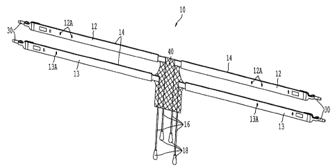
[0013] Figure 1 is a perspective view of a first embodiment of a support
apparatus of the
present invention;
[0014] Figure 2 is a fragmentary front view of a first embodiment of the
support apparatus;
[0015] Figure 3 is a side view of a strap of a support apparatus of the
present invention;
[0016] Figure 4 is a top view of a front view of a strap of a support
apparatus of the present
invention;
[0017] Figure 5 is a fragmentary front view of a second embodiment of a
support apparatus
of the present invention;
[0018] Figure 6 is a fragmentary front view of a third embodiment of a support
apparatus of
the present invention;
[0019] Figure 7 is a front view of a biologic graft attached to a central
portion of two straps,
each strap having a connector at each end;
[0020] Figure 8 is a front view of a support member including both a biologic
graft and a
synthetic support member;
[0021] Figure 8A is a side view of a support member including both a biologic
graft and a
synthetic support member;
[0022] Figure 9 is a front view of a support member of the second embodiment
of the
support apparatus;
[0023] Figure 10 is a front view of a support member of the first embodiment
of the support
apparatus;
[0024] Figure 11 is a close up view of the weave pattern of an embodiment of
the support
apparatus;
[0025] Figure 11A is a close up view of an alternate weave pattern for the
support member;
[0026] Figure 12 is a front view of a surgical kit of an embodiment of the
present invention;
[0027] Figure 13 is a perspective view of an embodiment of a right superior
needle (the
superior needle held in the surgeon's right hand) of the present invention;
[0028] Figure 14 is a top view of an embodiment of the right superior needle
of the present
invention;
[0029] Figure 15 is a bottom view of an embodiment of the right superior
needle of the
present invention;
[0030] Figure 16 is a left side view of an embodiment of the right superior
needle of the
present invention;
3
CA 02557938 2006-08-30
WO 2005/110274 PCT/US2005/015725
[0031] Figure 17 is a right side view of an embodiment of the right superior
needle of the
present invention;
[0032] Figure 18 is a front view of an embodiment of the right superior needle
of the present
invention;
[0033] Figure 19 is a rear view of an embodiment of the right superior needle
of the present
invention;
[0034] Figure 20 is a side perspective view of an embodiment of a left
inferior needle shaft
of the present invention, without a handle;
[0035] Figure 21 is a front perspective view of an embodiment of the left
inferior needle
shaft of the present invention, without a handle;
[0036] Figure 22 is a right side view of an embodiment of a left inferior
needle shaft of the
present invention, without a handle;
[0037] Figure 23 is a bottom view of an embodiment of the left inferior needle
shaft of the
present invention, without a handle;
[0038] Figure 24 is a front view of an embodiment of the left inferior needle
shaft of the
present invention, without a handle;
[0039] Figure 25 is a front view of an embodiment of a left superior strap
connector having
symbolic indicia thereon;
[0040] Figure 26 is a front view of an embodiment of a right superior strap
connector having
symbolic indicia thereon;
[0041] Figure 27 is a front view of an embodiment of a left inferior strap
connector having
symbolic indicia thereon;
[0042] Figure 28 is a front view of an embodiment of a right inferior strap
connector having
symbolic indicia thereon;
[0043] Figure 29 is a front view of an embodiment of a set of four needles and
a support
apparatus with four. connectors, wherein the connectors are matched to the
needles using
colors;
[0044] Figure 30 is a perspective view of a first needle tip and connector of
an embodiment
of the present invention;
[0045] Figure 31 is a perspective view of a second needle tip and connector of
an
embodiment of the present invention;
[0046] Figure 32 is a front view of a patient showing the four needle entry
incisions;
[0047] Figure 33 is a perspective view of a right superior needle tip entering
the left superior
incision (the superior incision on the patient's left side);
4
CA 02557938 2008-11-28
50239-11
[0048] Figure 34 is a perspective view of a right superior needle tip exiting
the vaginal
incision;
[0049] Figure 35 is a front view of a right superior needle tip exiting the
vaginal incision;
[0050] Figure 36 is a perspective view of a right superior needle tip
connected to the right
superior connector (the superior connector on the surgeon's right side);
100511 Figure 37 is a perspective view of the superior straps and the support
member in
place and the inferior straps extending outside the vaginal incision;
[0052] Figure 38 is a perspective view of a right inferior needle tip exiting
the vaginal
incision;
[0053] Figure 39 is a perspective view of all the straps and the support
member in place and
the sheaths removed;
[0054] Figure 40 is a flow chart illustrating a method of practicing the
present invention; and
[00551 Figure 41 is a flow chart illustrating an alternate method of
practicing the present
invention.
DETAILED DESCRIPTION OF THE PREFERRED EMBODIMENTS
[0056] Referri.ng now to the drawings, wherein like reference numerals
designate identical or
corresponding parts throughout the several views.
[00571 Figures 1 and 2 illustrate a surgical support apparatus 10 of a fnst
embodiment of the
present invention. The apparatus 10 is configured to be surgically implanted
in a female
patient to repair anterior prolapse of the vagina. The present invention may
be used to correct
central defects, midline defects, or both midline and central defects at once.
In the
embodiment shown in Figures 1 and 2, apparatus 10 comprises two superior
straps 12, two
inferior straps 13, a support member 40, and four loosening sutures 16. Each
of straps 12 and
13 include a connector 30. Each strap 12 and 13 is covered by a sheath 14.
Each suture 16
includes a tab 18. Straps 12 and 13 are connected to tabs 42 and 43 of support
member 40 by
known means.
[0058] In -one embodiment, sheath 14 is made of polyethylene. Other material
may be used,
such as polypropylene, nylon, polyester, or TeflonTM. The sheath is configured
to be removed
from the strap after the strap is in the correct position in the body.
100591 In one embodiment, straps 12 and 13 are 19.69 inches long and 0.433
inches wide.
The straps are 0.024 inches thick. Straps 12 and 13 are knitted of 4 or 6 mil
polypropylene
monofilament and are heat set at 280-300 degrees Fahrenheit for 5-8 minutes.
Also, in one
CA 02557938 2008-11-28
50239-11
embodiment, support member 40 is 10 cm long by. 5 cm wide and 0.021 inches
thick.
Member 40 is knitted of 4 mil polypropylene monofilament and heat set at 310-
330 degrees
Fahrenheit for 5-8 minutes. Both the strap and support member have a stitch
count of 27.5
course,dinch (12 courses) and 13 wales/inch ( 2 wales).
100601 In one embodiment, the straps are knitted with bar settings op Bar 1:
1/0, 2/1 and Bar
2: 0/1, 1/2. The support member is a large pore mesh, knitted with bar
settings of: Bar 1: 1/0,
2/3, 2/1, 2/3, 1/0,1/2,1/0, 112; Bar 2: 110, 2/3, 2/3, 1/0; and Bar 3:
2/3,1/0,1/2, 1/0, 2/3, 2/1,
2/3, 2/1. The straps are connected to the support member after knitting.
Weaving according
to a given bar pattern is described, for example, in "Warp Knitting
Production" by Dr. S. Raz,Melliand Textilberichte GmbH, Rohrbacher Str. 76, D-
6900 Heidelberg, Germany (1987).
100611 Straps 12 and 13 and or sheaths 14 may also include indicia thereon to
signify the
correct orientation for implantation into a patient. In the embodiment shown
in Figures 1 and
2, sheaths 14 around straps 12 include indicia 12A to show that straps 12 are
the superior
straps, and sheaths 14 around straps 13 include indicia 13A to show that
straps 13.are the
inferior straps. Words, symbols, and colors are all possible indicia that may
be used, and
these inodifications are intended to be within the spirit and scope of the
invention as claimed.
Further, the indicia may be located on the straps, the sheaths, or both.
[0062] Apparatus 10 includes dilating connectors 30. Suitable dilating
connectors are
disclosed in Published U.S. Patent Application Serial Nos. 2002/151762 and
2002/147382
and U.S. Patent Application Serial No. 2003/0176875.
[0063] Support member 40 is sized and shaped to afford repair of a cystocele
without lifting
the patient's bladder and without placing undue tension on the bladder or
vaginal wall. The
shape of member 40 may be predetennin.ed, or the member may be himmed based on
patient
anatomy before implantation.
10064] Figures 3 and 4 illustrate an embodiment of a strap for a surgical
apparatus of the
present invention. In one embodiment, strap 12 includes tensioning suture 17.
Tensioning
suture 17 passes through the mesh of strap 12 multiple times, as shown in
Figures 3 and 4.
Tensioning suture 17 is affixed to strap 12 at points 19, to allow transfer of
tension from the
suture to the strap. In one embodiment, tensioning sutures are included in all
the straps of the
support apparatus. It should be readily apparent to one skilled in the art
that other
configvrations of tensioning sutures and attachment points to a mesh strap are
possible, and
these modifications are within the scope of the invention as claimed.
6
CA 02557938 2008-11-28
50239-11
[0065] Tensioning suture 17 is configured to eliminate siack in a strap that
is already
surgically implanted in the body. By tightening the strap with suture 17,
rather than pulling
on the strap itself, the surgeon prevents damage to the strap due to
deformation. Damage to
surrounding tissues due to excessive movement of the strap during adjustment
is also
avoided. Straps including tensioning sutures are disclosed in copending United
States Patent
Application No. 2004/0014048.
[0066J Strap 12 also includes a connection point for loosening suture 16. As
discussed
below, loosening suture 16 is pulled by the surgeon to loosen the installed
support member, if
necessary.
[0067] Figure 5 illustrates a second embodiment of the surgical support
apparatus of the
present invention. Apparatus 110 includes a biological graft for a support
member 140. To
attach the graft to straps 12 and 13, clamps 150 are used to hold the surfaces
of the strap and
member together. The surfaces are then secured together, as discussed below in
the method
for preparing the biologic graft. Straps 12 and 13, sheaths 14, and connectors
30 are
described above.
[0068) In another embodiment, biologic graft comes in a kit already secured to
straps 12 and
13. In this case, the preparation method below is unnecessary.
[0069] Figure 6 shows a third embodiment of the surgical support apparatus of
the present
invention. Apparatus 210 includes straps 12 and 13, sheaths 14, and support
member 240. In
this ernbodiment, support member 240 and straps 12 and 13 are continuously
knitted. Thus,
there is no seam between the straps and support member, as they are one
continuous piece.
This results in a thinner transition area 243 from the straps to the support
member, which
results in a less bulky apparatus for installment into the pafient. An
apparatus that is less
bulky will be less hlcely to abrade the surrounding tissue.
[0070] The support member is knitted with a first bar pattern, and the straps
are knitted with
a second bar pattem. This allows larger pores in the support member, creating
a support
member that is more flexible and more likely to allow tissue ingrowth. A
second bar pattern
for the; straps allows a smaller pore size for the straps, creating a strap
that can carry a larger
load with a smaller, less intrusive strap width.
[0071]1 In one embodiment, the straps and support member are continuously
knitted of 4 mil
polypi-opylene monofilaments, knitted with a warp tricot. The stitch count is
27.5
courses/inch (12 courses) and 13 wales/inch ( 2 wales). The support member is
a large pore
mesh, with bar settings of Bar 1: 1/0, 2/3, 2/1, 2/3, 1/0, 1/2, 1/0, 1/2; Bar
2: 1/0, 2/3, 2/3, 1/0;
7
CA 02557938 2006-08-30
WO 2005/110274 PCT/US2005/015725
and Bar 3: 2/3, 1/0, 1/2, 1/0, 2/3, 2/1, 2/3, 2/1. The thickness of the
support member is about
0.21 inches.
[0072] Figure 7 shows an alternate embodiment of the surgical apparatus of the
present
invention. Apparatus 310 includes straps 312 and 313 and biologic graft 140.
Straps 12 and
13 have connectors 30 at each end thereof. Biologic graft 140 is connected to
a central
portion of each strap. In the embodiment shown in Figure 7, biologic graft 140
is connected
to strap 12 and strap 13 at a portion equidistant from each end of the straps.
It should be
readily apparent to one skilled in the art that other configurations are
possible, and these
modifications are within the scope of the invention as claimed.
[0073] Figures 8 and 8A illustrate a surgical apparatus according to another
alternate
embodiment of the present invention. Apparatus 410 includes a biologic graft
140 and a
synthetic support member 40. In the embodiment shown in Figures 8 and 8A,
biologic graft
140 and synthetic support member 40 have the same area and are attached to
overlie one
another. However, it should be readily apparent to one skilled in the art that
a surgical
support apparatus having a biologic graft and a synthetic support member
having different
areas and/or offset from one another could be used, and these modifications
are within the
scope of the invention as claimed. Further, apparatus 410 may be implanted in
the patient
such that biologic graft 140 faces the bladder and support member 40 faces the
vaginal wall,
or such that biologic graft 140 faces the vaginal wall and support member 40
faces the
bladder. The implantation configuration is based on the preference of the
surgeon.
[0074] Figure 9 shows support member 140 made of a non-synthetic material.
Suitable non-
synthetic materials include allografts, homografts, heterografts, autologous
tissues, cadaveric
fascia, autodermal grafts, dermal collagen grafts, autofascial heterografts,
whole skin grafts,
porcine dermal collagen, lyophilized aortic homografts, preserved dural
homografts, bovine
pericardium and fascia lata. Member 140 includes tabs 142 and 143 for
connecting to straps,
as shown in Figure 5.
[0075] Figure 10 shows support member 40 made of a synthetic material. Member
40
includes tabs 42 and 43 for connecting to straps, as shown in Figure 1.
Commercial examples
of synthetic materials include MarlexTM (polypropylene) available from Bard of
Covington,
R. I., ProleneTm (polypropylene), Prolene Soft Polypropylene Mesh or Gynemesh
(nonabsorbable synthetic surgical mesh), both available from Ethicon, of New
Jersey, and
Mersilene (polyethylene terphthalate) Hernia Mesh also available from Ethicon,
Gore-TexTM
(expanded polytetrafluoroethylene) available from W. L. Gore and Associates,
Phoenix,
Ariz., and the polypropylene sling available in the SPARCTM sling system,
available from
8
CA 02557938 2008-11-28
50239-11
American Medical Systems, Inc. of Minnetonka, Minn, DexonTM (polyglycolic
acid)
available from Davis and Geck of Danbury, Conn., and Vicrylm available Erom
Ethicon.
[0076] Other examples of suitable materials include those disclosed in
published U.S. patent
application Ser. No. 2002/0072694. More specific examples of synthetic
materials include,
but. are not limited to, polypropylene, cellulose, polyvinyl, silicone,
polytetrafluoroethylene,
polygalactin, Silastic, carbon-fiber, polyethylene, nylon, polyester (e.g.
Dacron)
11~Tm
polyanhydrides, polycaprolactone, polyglycolic acid, poly-L-lactic acid, poly-
D-L-lactic acid
and polyphosphate esters. See Cervigni et al., The Use ofSynthetics in the
Treatment of
Pelvic Organ Prolapse; Cun'ent Opinion in Urology (2001), 11: 429-435.
[0077] Figures 11 and 11A illustrate two possible embodiments for the
stitching of synthetic
support member 40. However, it should be readily apparent to one sldlled in
the art that other
knitting patterns are possible, and these modifications are within the scope
of the invention as
claimed.
(0078] Referring to Figure 12, in another aspect, the present invention
includes a surgical lat
400. 1he kit 400 preferably includes at least two superior needles 70R and
70L. Right
superior needle 70R is configured to be held in the surgeon's right hand and
such that tha tip
of the needle enters an incision on the left side of the patient where the
left adductor longus
tendon of the patient inserts into a left portion of the pubic ramus bone of
the patient, lateral
to the edge of the pubic ramus bone, and travels through the top of the left
obturator foramen
to exit through an incision in the vagina of the patient. Left superior needle
70L is configured
to be held in the surgeon's left hand and such that the tip of the needle
enters an incision on
the right side of the patient where the right adductor longus tendon of the
patient inserts into a
iight portion of the pubic ramus bone of the patient, lateral to the edge of
the pubic ramus
bone, and travels through the top of the right obturator foramen to exit
through an incision in
the vagina of the patient.
[0079) In various embodiments of the present invention, the kits may fnrther
include the
needles described in published U.S. patent application Ser. Nos. 20023-0065246-
Al; 2002-
0151762-Al; 2002-0147382-Al; 2002-0107430-A1, U.S. patent application Ser. No.
2002-
0099258-A 1 and U.S. patent application Ser. No. 2002-0099259-A 1. In an
embodiment tbat is particularly
suitable for a transobturator surgical procedure, the needles include needles
as described in U.S. patent
application Ser. No. 2003/0171644.
9
CA 02557938 2006-08-30
WO 2005/110274 PCT/US2005/015725
[0080] The individual elements of the kits of the present invention may be
packaged together
as shown in Figure 12 with a cover 52 and tray 54. Alternatively, the
individual elements
may be separately packaged or packaged in subassemblies depending on a variety
of factors
such as shelf life and sterilization requirements. They may be assembled at
the
manufacturing location or at the healthcare location. Any suitable
sterilization procedure may
be utilized to sterilize the contents of a kit. Suitable sterilization
techniques include, but are
not limited to, steam, ethylene oxide, electron beam, vapor (e.g. hydrogen
peroxide or
peracetic acid), gamma or plasma procedures.
[0081] The kit shown in Figure 12 includes a support apparatus including a
mesh support
member 40. It should be readily apparent to one skilled in the art that kits
using biological
support members, as described above, may be made, and these modifications are
within the
scope of the invention as claimed. Further, a kit comprising a biologic graft
may have the
biologic graft pre-attached to the straps, or the graft may be separate from
the straps and
require the surgeon to attach the straps to the graft, as discussed below.
[0082] The kit shown in Figure 12 also includes four needles: right inferior
needle 60R, left
inferior needle 60L, right superior needle 70R, and left superior needle 70L.
Embodiments of
these needles are shown in Figures 13-24 and are described herebelow.
[0083] Figures 13-19 illustrate an embodiment of right superior needle 70R of
the present
invention. (Left superior needle 70L is a mirror image of the right superior
needle 70R.)
Right superior needle 70R includes indicia 71R, handle 72R, shaft 74R, curved
portion 76R,
and tip portion 78R. Indicia 71R designates whether the needle is the right or
left needle by
pointing to the surgeon's right or left side, as the surgeon holds the needle
handle. (The
surgeon's right side corresponds to the patient's left side.)
[0084] Figures 20-24 illustrate an exemplary shaft of left inferior needle
60L, without handle
62L. (Right inferior needle 60R is a mirror image of the left inferior needle
60L.) Left
inferior needle 60L includes a handle 62L, a shaft 64L, a curved portion 66L,
and a tip
portion 68L. Left inferior needle 60L is configured to be held in a surgeon's
left hand such
that tip 68L enters an incision 530L on the right side of the patient where a
right inferior edge
of the pubic ramus bone of the patient ends at a bottom of the right obturator
foramen of the
patient, and travels through the right obturator foramen to exit through an
incision in the
vagina of the patient. Right inferior needle 60R is configured to be held in a
surgeon's right
hand such that tip 68R enters an incision on the left side of the patient
where a left inferior
edge of the pubic ramus bone of the patient ends at a bottom of the left
obturator foramen of
CA 02557938 2006-08-30
WO 2005/110274 PCT/US2005/015725
the patient, and travels through the left obturator foramen to exit through an
incision in the
vagina of the patient. This is shown in Figure 38.
[0085] The above-described needles may be disposable or reusable.
[0086] Figures 25-28 show connectors of the present invention having indicia
thereon.
Figure 25 shows left superior connector 330A having indicia 331. Indicia 331
includes
symbol 331A indicating that the connector is the left superior connector.
Figure 26 shows
right superior connector 330B having indicia 331. Indicia 331 includes
symbo1331B
indicating that the connector is the right superior connector. Figure 27 shows
left inferior
connector 330C having indicia 331. Indicia 331 includes symbo1331C indicating
that the
connector is the left inferior connector. Figure 28 shows right inferior
connector 330D
having indicia 331. Indicia 331 includes symbol 33 1D indicating that the
connector is the
right inferior connector. Right connectors are located on the surgeon's right
side and left
connectors are located on the surgeon's left side.
[0087] Figures 25-28 show connectors including symbolic indicia to identify
each connector.
It should be readily apparent to one skilled in the art that other symbols,
markings, or words
could be used to identify the connectors, and that these modifications are
within the scope of
the invention as claimed.
[0088] Figure 29 shows another embodiment of the present invention wherein
connectors
and the handles of the corresponding needles are matching colors. For example,
the color of
the handle of needle 70L matches the color of connector 430A. The color of the
handle of
needle 70R matches the color of connector 430B. The color of the handle of
needle 60R
matches the color of connector 430D. The color of the handle of needle 60L
matches the
color of connector 430C.
[0089] Figures 30 and 31 are perspective views of a needle tips having a cross
sections that
are configured to match the cross sections of a connector aperture. Figure 30
shows that the
cross section of portion 450A of needle tip portion 478A is a triangle. The
cross section of
portion 450A matches triangle shaped aperture 460A in connector 490A. Figure
31 shows
that the cross section of portion 450B of needle tip portion 478B is a square.
The cross
section of portion 450B matches square shaped aperture 460B in connector 490B.
[0090] In one embodiment, each needle tip has a cross section that matches the
cross section
of an aperture of the corresponding connector, and the tip cross section is
incompatible with
the other connector apertures. For example, the cross section of the portion
450A, a triangle,
would not fit in aperture 460B, a square, and vice versa. Thus, even if the
connectors are
confused, it is physically impossible for a surgeon to insert the needle tip
in the incorrect
11
CA 02557938 2006-08-30
WO 2005/110274 PCT/US2005/015725
connector without damaging the tip or connector. It should be readily apparent
to one skilled
in the art that other shaped tips and apertures are possible, and these
modifications are within
the scope of the invention as claimed.
[0091] Example of a Surgical Procedure
[0092] The following description, illustrated in Figures 32-39, is an
exemplary method for
using the disclosed surgical support apparatus 10 having a mesh support member
40. It
should be readily apparent to those skilled in the art that modifications may
be made to the
following method, and these modifications are within the scope of the
invention as claimed.
[0093] If the embodiment of the surgical support apparatus 110 including a
biological
support member 140 is used, the biological support member 140 must be prepared
before
making the vaginal incision. Instructions for preparing the biological support
member are
given after the present description.
[0094] In preparation for surgery, the patient is placed in a modified dorsal
lithotomic
position with hips flexed, legs elevated in stirrups and buttocks even with
edge of the surgical
table. The patient's bladder is emptied. A catheter is not required during the
procedure, but
may aid in identifying the urethra during the procedure. A weighted vaginal
retractor or other
suitable vaginal retraction is used, if desired.
[0095] The length of the vaginal incision is marked with a skin pencil
starting below the
bladder neck, over the most prominent part of the prolapse, to the lowermost
part of the
prolapse. (Variations may occur in specific incisions due to individual
technique and patient
anatomy.) An incision is made over this marking. The incision site may be
infiltrated with
saline, if desired. An Allis forceps is placed on the incision margin to
expose the incision.
The patient's bladder is dissected off the vagina up to the lateral sulcus and
posterior to the
vaginal vault. This dissection allows palpation of the medial edge of the
inferior pubic
ramus, assisting in guiding the superior and inferior needles to the exit
points free from the
bladder. The patient's cystocele is then reduced using midline plication, if
desired.
[0096] Next, markings are made to identify the locations for needle entry
incisions. The
vaginal dissection is completed prior to marking needle entry incisions to
allow for digital
palpation along the ischiopubic ramus. The needle entry points are palpated
internally and
externally with the thumb and index fmger before marking, as discussed
hereafter.
[0097] The edge of the ischiopubic ramus beginning at the level of the vaginal
incision is
palpated, continuing along the edge of the bone cephalad toward the level of
the clitoris
denoting where the adductor longus tendon inserts into the pubic ramus. The
superior skin
incisions are marked approximately at this location and lateral to the edge of
the bone. The
12
CA 02557938 2006-08-30
WO 2005/110274 PCT/US2005/015725
markings are made according to the same method on both sides (right and left)
of the
patient's body. Both marks lie in a straight line at the approximate level of
the clitoris. The
edge of the inferior pubic ramus is palpated until it ends at the bottom of
the obturator
foramen. The inferior skin incisions are then marked. The inferior skin
incisions are located
at a point approximately 3 centimeters below and 2 centimeters lateral to the
superior marks.
Again, the markings are made according to the same method on both sides of the
patient's
body.
[0098] A small vertical stab incision is made over all four markings to
provide needle entry
incisions. Right superior incision 540R, left superior incision 540L, right
inferior incision
530R, and left inferior incision 530L are all shown in Figure 32. (Right and
left with regard
to the incisions are the patient's right and left sides.)
[0099] The above-described surgical kit is opened. The package integrity is
checked to
ensure that the kit was not compromised in shipping, and the components of the
kit are
inspected for damage.
[00100] The following method describes the straps on the surgeon's right side
(the patient's
left side) being surgically installed before the straps on the surgeon's left
side (the patient's
right side). However, it should be readily apparent to one skilled in the art
that the straps of
either side could be installed first, and this modification is within the
scope of the invention
as claimed.
[00101] Tip 78R of right superior needle 70R is now inserted through left
superior incision
540L, through the left obturator foramen, and then through the vaginal
incision 524. Tip of
right superior needle 70R is pointed perpendicular to the skin with tip 78R in
the left superior
incision 540L, shown in Figure 33. The thumb from the surgeon's right hand is
on the
outside curve of needle to control the needle movement as it perforates the
obturator
membrane and muscle. The right thumb pushes the needle through the obturator
muscle and
membrane. The needle shaft and handle is positioned at a 45 angle to the
patient's vertical
axis and close to the patient's body. The needle handle is rotated to move the
needle tip and
curve around the posterior surface of the ischial pubic ramus toward the
vaginal incision and
index finger. (If the needle tip hits the pubic bone during rotation, the
needle is retracted.
The needle tip is then penetrated beyond initial insertion depth and rotate
again toward the
vaginal incision.) The needle tip is palpated with the surgeon's finger. The
finger meets the
needle tip as it moves around the pubic ramus. (If the needle tip can not be
located, the
needle tip is retracted to just behind the pubic ramus and advanced again.)
The needle tip is
13
CA 02557938 2006-08-30
WO 2005/110274 PCT/US2005/015725
guided by the surgeon with the surgeon's fmger towards the vaginal incision
until the needle
tip extends through the vaginal incision, shown in Figures 34 and 35.
[00102] The support member is then oriented so that the tail of the graft is
pointing away
from the surgeon. (The marking indicia disclosed herein may be used to
determine the
correct orientation of the support member.) The right superior connector is
connected to the
tip of the right superior needle, the tip extending out of the vaginal
incision, as shown in
Figure 36. The superior needle connectors are closest to the leading edge of
the graft that
will be below the bladder neck.
[00103] Before attaching the connectors, the surgeon ensures that the self-
fixating mesh and
graft are not twisted, as the connectors are not removable once snapped onto
the needle.
Once the connector is attached to the needle, the needle is rotated back
through the skin
incision pulling the connector and associated plastic insertion sheath and
graft into position.
[00104] The above process is repeated with the left needle on the patient's
right side. The
partially implanted apparatus is shown in Figure 37, with superior straps and
support member
40 implanted and the inferior straps extending outside the body through the
vaginal incision.
[00105] The insertion sheaths and mesh are then cut below the blue mark on the
end portion
of the plastic sheath and discarded. This step allows the sheath to slide
freely relative to the
mesh. The sheaths are not removed at this time.
[00106] The tip of the right inferior needle is now inserted through left
inferior incision
530L, through the left obturator foramen, and then through the vaginal
incision. The tip of
the right inferior needle is pointed perpendicular to the skin with the tip in
the left inferior
incision. The exit point for the needle is confirmed to be clear of the
bladder wall by the
surgeon placing their right index finger at the distal end of the vaginal
incision and
visualizing where needle exits the distal end of vaginal incision. The
surgeon's right thumb
is on the outside curve of needle to control the needle movement as it
perforates the obturator
membrane and muscle. The right thumb pushes the needle through the obturator
muscle and
membrane.
[00107] The needle shaft and handle is positioned parallel to the patient's
vertical axis and
close to the patient's body. The needle handle is rotated, moving the needle
tip and curve
toward the distal end of the vaginal incision. The surgeon is careful to avoid
buttonholing the
fornix to prevent bleeding. The needle tip is palpated as it moves through the
distal end of
the vaginal incision. The right inferior needle tip is shown extending outside
the vaginal
incision in Figure 38.
14
CA 02557938 2006-08-30
WO 2005/110274 PCT/US2005/015725
[00108] The right inferior connector is connected to the right inferior needle
tip. Again,
before attaching the connectors, the surgeon ensures that the self-fixating
mesh and graft are
not twisted, as the connectors are not removable once snapped onto the needle.
The needle is
rotated back through the skin incision pulling the connector and associated
plastic insertion
sheath and graft into position.
[00109] The above process is repeated with the left inferior needle on the
patient's right side.
[00110] The insertion sheath and mesh are then cut below the blue mark on the
end portion
of the plastic sheath and discarded. This step allows the sheath to slide
freely relative to the
mesh. The sheaths are not removed at this time.
[00111] A cystoscopy is done to check the integrity of the ureters and
bladder.
[00112] Any vaginal retraction is now removed to allow adjusting the tension
of the mesh to
reduce bladder bulge. The surgeon confirms the mesh is lying flat and not
overlapping under
the vaginal wall. The superior leading edge of the support member should be
positioned
below the bladder neck without tension. The inferior tail portion of the
support member
should be positioned at the distal end of the vaginal incision or towards the
vaginal apex
without tension.
[00113] If the mesh needs to be loosened, an instrument is placed between the
mesh and
vaginal wall and pulled down, or away from the vaginal wall until proper
tension is acliieved.
[00114] Each of the four plastic sheaths are removed and discarded, while
ensuring the
support member graft is not being over tensioned. Once the plastic sheaths are
removed,
further adjustment is minimized.
[00115] If the mesh needs to be tightened, the tensioning suture exiting the
skin incision on
each side is grasped using a hemostat. The suture is wrapped around the
hemostat to improve
the grip and pulled up or out to tighten until proper tension is achieved.
[00116] To loosen a biologic graft, the surgeon uses a hemostat or a clamp to
pull from each
of the hanging loosening sutures. The surgeon uses the clamps to pull down and
loosen the
strap mesh as desired. The surgeon is careful not to pull on tab 18 on
loosening suture 16 to
loosen the strap mesh.
[00117] The surgeon cuts one end of each loosening sutures and pulls tab 18
until the entire
loosening suture is removed. The mesh is then trimmed at the level of the
subcutaneous
tissue and all five incisions are closed. Excess vaginal tissue may be
excised. Variations of
this step may occur due to individual technique and patient anatomy. The fmal
implanted
apparatus is shown in Figure 39.
CA 02557938 2006-08-30
WO 2005/110274 PCT/US2005/015725
[00118] After the operation, a catheter and/or vaginal pack can be used at the
discretion of
the surgeon. It is removed prior to discharge. Antibiotic prophylaxis should
be given. The
ability of the patient to empty the bladder should be confirmed prior to
discharge.
[00119] If a biologic graft is used, the following steps are performed before
making the
vaginal incision. The biologic graft is removed from the package and prepared
per included
instructions, if needed. A precut biologic is prepared by orienting the graft
with the tail
portion pointing at the surgeon. Beginning with the right or left inferior
landing tabs on the
biologic graft (closest to the surgeon), the graft is attached to clamps 150.
Attaching the
inferior tabs frst allows space to attach the two superior mesh appendages
with the clamp.
The clamps are squeezed to separate mesh tape. The graft material is inserted
into the open
clamp using printed marks as guides to center the graft. (The printed side of
the plastic
sheath is facing the surgeon as the surgical apparatus is placed in the body.)
The clamp is
released to secure graft material. A desired suture is passed up through the
clamp using a
suturing mark as a guide. The suture is then passed down using the opposite
suturing mark as
the guide. The passed sutures are then secured using the surgeon's knot(s) of
choice.
Additional throws are made if needed. The clamp sutures are cut by passing a
scissors or a
scalpel down the scissors slot on each side of the clamp. The clamps are then
removed. The
clamp attachment sutures remain wi.th the clamp. The surgeon assesses the
attachment of the
graft material mesh tape. The protective sheath is slid over the mesh
connection to aid
deployment.
[001201 The preceding steps are repeated on the opposite side of the graft.
The sutures are
passed such that the attachment knots are all on the same side of the graft.
The biologic is
placed in a saline bath to keep it hydrated during the remainder of the
procedure. The graft
tail is trimmed at the time of vaginal marking and dissection to reflect
patients anatomy, if
needed.
[00121] In addition, when using the biologic graft, the surgeon is careful
when drawing the
strap through the body that the sheath covers the graft connections and that
the graft material
and graft connections are not damaged.
[00122] Figure 40 illustrates one embodiment of method of practicing the
present invention.
Method 600 includes the steps of: establishing four pathways in tissue around
a bladder of a
patient (step 610), introducing a strap into each of the pathways (step 620),
and positioning
beneath the bladder of the patient a support member having each strap
connected thereto such
that the bladder of the patient is supported by the support member and a bulge
of the bladder
into the vagina of the patient is reduced (step 630). Step 610 comprises the
steps of: making
16
CA 02557938 2008-11-28
50239-11
an incision in the vagina of the patient (step 612), making an incision on a
left side of the
patient where a left adductor longus tendon of the patient -inserts into a
left portion. of the
pubic ramus bone of the patient, lateral to an edge of the pubic ramus bone
(step 614),
making an.incision on a right side of the patient where a right adductor
longus tendon of the
patient iniserts into a right portion of the pubic ramus bone of the patient,
lateral to an edge of
the pubic ramus bone (step 616), making an incision on a left side of the
patient where a left
inferior edge of the pubic ramus.bone of the patient ends at the bottom of the
left obturator
foramen of the patient (step 618), and making an incision on a right side of
the patient where
a right inferior edge of the pubic ramus bone of the patient ends at the
bottom of the right.
obturator foramen of the patient (step 619).
[001231 Figure 41 illustrates an alternate embodiment of method of practicing
the present
invention. Method 700 includes the steps of: establishing four pathways in
tissue around a
bladder of a patient (step 710), atraumatically dilating the pathways (step
720), introducing a
strap into each of the pathways while the pathways are atraumatically dilated
(step 730), and
positioning beneath the bladder of the patient a support member having eacli
strap connected
thereto such that the bladder of the patient is supported by the support
member and a bulgeof
the bladder into the vagina of the patient is reduced (step 740). Step 710
comprises the steps
of: making an incision in the vagina of the patient (step 712), making an
incision on a left
side of the patient where a left adductor longus tendon of the patient inserts
into a left portion
of the pubic ramus bone of the patient, lateral to an edge of the pubic ramus
bone (step 714),
making an incision on a right side of the patient where a iight adductor
longus tendon of the
patient inserts into a right portion of the pubic ramus bone of the patient,
lateral to the edge of
the pubic ramus bone (step 716), making an incision on a left side of the
patient where a left
inferior edge of the pubic ramus bone of the patient ends at the bottom of the
left obturator
forame:n of the patient (step 718), and making an incision on a right side of
the patient where
a right inferior edge of the pubic ramus bone of the patient ends at the
bottom of the right
obturator foramen of the patient (step 719).
[001241 Obviously, numerous modifications and variations of the present
invention are
possible in light of the above teachings. It is therefore to be understood
that within the scope
of the appended claims, the invention may be practiced otherwise than as
specifically
described herein.
17