Note: Descriptions are shown in the official language in which they were submitted.
CA 02558386 2006-08-29
WO 2006/009049 PCT/JP2005/012970
1
Description
Hybrid Vehicle, Control Method of Hybrid Vehicle, and Power
Output Apparatus
Technical Field
The present invention relates to a hybrid vehicle, a
control method of the hybrid vehicle, and a power output
apparatus.
Background Art
One proposed hybrid vehicle has an engine, a planetary
gear unit including a carrier and a ring gear respectively
linked to a crankshaft of the engine and to a drive shaft, a
first motor connected to a sun gear of the planetary gear unit,
a second motor connected to the drive shaft, and a battery
capable of transmitting electric power to and from the first
motor and the second motor (see, for example, Japanese Patent
Laid-Open Gazette No. 11-93727). In this proposed hybrid
vehicle, the first motor is driven and controlled to regulate
the rotation speed of the engine.
Disclosure of the Invention
In the hybrid vehicle equipped with the engine and the
driving motor, the general control procedure varies the
rotation speed of the engine and intermittently activates and
inactivates the engine with a variation in required engine power,
CA 02558386 2006-08-29
WO 2006/009049 PCT/JP2005/012970
2
in order to enhance the energy efficiency. In response to the
driver's deceleration demand, the required engine power
basically decreases to 0 or to a braking power level (friction
work) and accordingly lowers the engine rotation speed. The
driver may give a high acceleration demand immediately after
the deceleration demand. The driving motor is activated with
electric power supply from the battery to compensate for an
insufficient power due to a poor response of the engine. A
high-capacity battery sufficiently supplies required electric
power to supplement the power insufficiency, but naturally has
large dimensions and mass to be unsuitable for the equipment
of the hybrid vehicle. A low-capacity battery, however, can
not sufficiently supply required electric power to supplement
the power insufficiency. A large power insufficiency
increases the required electric power to be discharged from the
battery. Repeated charges and discharges of the battery with
relatively large electric powers even within an allowable range
of input and output limits undesirably cause premature
deterioration of the battery.
The hybrid vehicle, the control method of the hybrid
vehicle, and the power output apparatus of the invention thus
aim to enhance a response to a demand for varying power output
from an internal combustion engine. The hybrid vehicle, the
control method of the hybrid vehicle, and the power output
apparatus of the invention also aim to reduce the loading of
an accumulator unit, such as a secondary battery. The hybrid
CA 02558386 2006-08-29
WO 2006/009049 PCT/JP2005/012970
3
vehicle, the control method of the hybrid vehicle, and the power
output apparatus of the invention further aim to enhance the
energy efficiency of the hybrid vehicle or the power output
apparatus.
At least part of the above and the other related obj ects
are attained by the hybrid vehicle, the control method of the
hybrid vehicle, and the power output apparatus having the
configurations and arrangements discussed below.
The present invention is directed to a hybrid vehicle
ZO including: an internal combustion engine; an electric
power-mechanical power input output mechanism that.is connected
to an output shaft of the internal combustion engine and to a
drive shaft linked with one axle of the hybrid vehicle and inputs
and outputs power from and to the output shaft and the drive
~5 shaft through input and output of electric power and mechanical
power; a motor that inputs and outputs power from and to either
of the one axle and the other axle, which is different from the
one axle; an accumulator unit that transmits electric power to
and from the electric power-mechanical power input output
20 mechanism and the motor; a drive power demand setting module
that sets a drive power demand required for a drive of the hybrid
vehicle; a vehicle speed measurement module that measures
vehicle speed of the hybrid vehicle; a lower rotation speed
limit setting module that sets a lower rotation speed limit,
25 which represents a minimum allowable rotation speed of the
internal combustion engine, corresponding to the measured
CA 02558386 2006-08-29
WO 2006/009049 PCT/JP2005/012970
4
vehicle speed; and a control module that controls the internal
combustion engine, the electric power-mechanical power input
output mechanism, and the motor to drive the internal combustion
engine at a rotation speed of not lower than the set lower
rotation speed limit and to drive the hybrid vehicle with a power
corresponding to the set drive power demand.
The hybrid vehicle of the invention sets the lower
rotation speed limit, which is the minimum allowable rotation
speed of the internal combustion engine, corresponding to the
measured vehicle speed. The internal combustion engine, the
electric power-mechanical power input output mechanism, and the
motor are controlled to drive the internal combustion engine
at a rotation speed of not lower than the set lower rotation
speed limit and to drive the hybrid vehicle with a power
corresponding to the set drive power demand. The internal
combustion engine may increase the output power by increasing
only the rotation speed with a fixed output torque or by
increasing only the output torque with a fixed rotation speed.
The output torque increase attained by varying the intake air
flow and the amount of fuel inj ection requires a less time than
the rotation speed increase. The output power increase with
the output torque variation can thus be attained within a
shorter time period than the output power increase with the
rotation speed variation. The internal combustion engine
driven at the rotation speed of not lower than the lower rotation
speed limit, which depends upon the measured vehicle speed, has
CA 02558386 2006-08-29
WO 2006/009049 PCT/JP2005/012970
a quicker response to a demand for a power increase to be output
from the internal combustion engine. This arrangement
desirably decreases the output power of the motor, which is
activated to compensate for an insufficiency of the power
5 required for driving the hybrid vehicle due to a delayed
response of the internal combustion engine, thus effectively
reducing the loading of the accumulator unit.
In one preferable embodiment of the invention, the hybrid
vehicle further includes a rotation speed demand setting module
that sets a rotation speed demand, at which the internal
combustion engine is to be driven, corresponding to the set
drive power demand. The control module controls the internal
combustion engine, the electric power-mechanical power input
output mechanism, and the motor to drive the internal combustion
engine at a higher rotation speed between the set lower rotation
speed limit and the set rotation speed demand. The internal
combustion engine is thus driven at the rotation speed
determined by taking into account both the rotation speed demand,
which depends upon the drive power demand, and the lower
rotation speed limit, which depends upon the vehicle speed.
Namely the internal combustion engine is driven at an adequate
drive point . The rotation speed demand setting module may set
the rotation speed demand to a specific rotation speed of the
internal combustion engine that ensures efficient output of the
power corresponding to the set drive power demand from the
internal combustion engine. This arrangement maintains the
CA 02558386 2006-08-29
WO 2006/009049 PCT/JP2005/012970
6
high response of the internal combustion engine, while
enhancing the energy efficiency of the hybrid vehicle.
In the hybrid vehicle of the invention, it is preferable
that the lower rotation speed limit setting module sets the
lower rotation speed limit to a rotation speed of not lower than
a specific rotation speed of the internal combustion engine at
a specific drive point that ensures efficient output of a
required power from the internal combustion engine for a
constant-speed drive of the hybrid vehicle on substantially
flat road surface at the measured vehicle speed. Even in the
case of a small current power demand to be output from the
internal combustion engine, this arrangement enables the
internal combustion.engine to promptly output a power required
for a constant-speed drive of the hybrid vehicle or a greater
I5 power, in response to a subsequent demand for an output power
variation.
In the hybrid vehicle of the invention, it is also
preferable that the control module controls the internal
combustion engine, the electric power-mechanical power input
output mechanism, and the motor to stop fuel injection to the
internal combustion engine, when the set drive power demand is
equivalent to a predetermined braking power for braking the
hybrid vehicle. This arrangement improves the fuel
consumption and enhances the total energy efficiency of the
hybrid vehicle.
In the hybrid vehicle of the invention, it is preferable
CA 02558386 2006-08-29
WO 2006/009049 PCT/JP2005/012970
7
that the electric power-mechanical power input output mechanism
includes a three shaft-type power input output module that is
linked to three shafts, that is, the output shaft of the internal
combustion engine, the drive shaft, and a rotating .shaft, and
automatically determines power input from and output to a
residual one shaft based on powers input from and output to any
two shafts among the three shafts; and a generator that inputs
and outputs power from and to the rotating shaft . Further, it
is preferable that the electric power-mechanical power input
output mechanism includes a pair-rotor motor that has a first
rotor connected to the output shaft of the internal combustion
engine and a second rotor connected to the drive shaft and is
driven through relative rotation of the first rotor to the
second rotor.
The present invention is directed to a power output
apparatus that outputs power to a drive shaft and includes : an
internal combustion engine; an electric power-mechanical power
input output mechanism that is connected to an output shaft of
the internal combustion engine and to the drive shaft and inputs
and outputs power from and to the output shaft and the drive
shaft through input and output of electric power and mechanical
power; a motor that inputs and outputs power from and to the
drive shaft; an accumulator unit that transmits electric power
to and from the electric power-mechanical power input output
mechanism and the motor; a power demand setting module that sets
a power demand required for the drive shaft; a rotation speed
CA 02558386 2006-08-29
WO 2006/009049 PCT/JP2005/012970
8
measurement module that measures rotation speed of the drive
shaft; a lower rotation speed limit setting module that sets
a lower rotation speed limit, which represents a minimum
allowable rotation speed of the internal combustion engine,
corresponding to the measured rotation speed; and a control
module that controls the internal combustion engine, the
electric power-mechanical power input output mechanism, and the
motor to drive the internal combustion engine at a rotation
speed of not lower than the set lower rotation speed limit and
to output a power corresponding to the set power demand to the
drive shaft.
The power output apparatus of the invention sets the lower
rotation speed limit, which is the minimum allowable rotation
speed of the internal combustion engine, corresponding to the
measured rotation speed of the drive shaft. The internal
combustion engine, the electric power-mechanical power input
output mechanism, and the motor are controlled to drive the
internal combustion engine at a rotation speed of not lower than
the set lower rotation speed limit and to output a power
corresponding to the set power demand to the drive shaft. As
described above, the output power increase with the output
torque variation can be attained within a shorter time period
than the output power increase with the rotation speed variation .
The internal combustion engine driven at the rotation speed of
not lower than the lower rotation speed limit, which depends
upon the measured rotation speed of the drive shaft, has a
CA 02558386 2006-08-29
WO 20061009049 PCT/JP2005/012970
9
quicker response to a demand for a power increase to be output
from the internal combustion engine. This arrangement
desirably decreases the output power of the motor, which is
activated to compensate for an insufficiency of the power
required for the drive shaft due to a delayed response of the
internal combustion engine, thus effectively reducing the
loading of the accumulator unit. The power output apparatus
of the invention may be mounted on a vehicle, which has one axle
linked with the drive shaft. The internal combustion engine
is then driven at a rotation speed of not lower than the lower
rotation speed limit, which depends upon the rotation speed of
the axle . The arrangement of setting the lower rotation speed
limit corresponding to the vehicle speed in place of the
rotation speed of the axle is within the scope of the
characteristics of the hybrid vehicle of the invention
described above. Namely the various embodiments and
arrangements of the hybrid vehicle of the invention described
above are applicable to the power output apparatus with
replacement of the vehicle speed by the rotation speed of the
drive shaft.
The present invention is directed to a control method of
a hybrid vehicle including : an internal combustion engine; an
electric power-mechanical power input output mechanism that is
connected to an output shaft of the internal combustion engine
and to a drive shaft linked with one axle of the hybrid vehicle
and inputs and outputs power from and to the output shaft and
CA 02558386 2006-08-29
WO 2006/009049 PCT/JP2005/012970
the drive shaft through input and output of electric power and
mechanical power; a motor that inputs and outputs power from
and to either of the one axle and the other axle, which is
different from the one axle; and an accumulator unit that
5 transmits electric power to and from the electric
power-mechanical power input output mechanism and the motor,
and the control method includes the steps of : (a) setting a drive
power demand required for a drive of the hybrid vehicle; (b)
setting a lower rotation speed limit, which represents a minimum
10 allowable rotation speed of the internal combustion engine,
corresponding to a measured vehicle speed; and (c) controlling
the internal combustion engine, the electric power-mechanical
power input output mechanism, and the motor to drive the
internal combustion engine at a rotation speed of not lower than
the set lower rotation speed limit and to drive the hybrid
vehicle with a power corresponding to the set drive power
demand.
The control method of the hybrid vehicle of the invention
sets the lower rotation speed limit, which is the minimum
allowable rotation speed of the internal combustion engine,
corresponding to the measured vehicle speed. The internal
combustion engine, the electric power-mechanical power input
output mechanism, and the motor are controlled to drive the
internal combustion engine at a rotation speed of not lower than
the set lower rotation speed limit and to drive the hybrid
vehicle with a power corresponding to the set drive power demand.
CA 02558386 2006-08-29
WO 2006/009049 PCT/JP2005/012970
11
This control procedure ensures a quick response of the internal
combustion engine to a demand for a power increase to be output
from the internal combustion engine. This arrangement
desirably decreases the output power of the motor, which is
activated to compensate for an insufficiency of the power
required for driving the hybrid vehicle due to a delayed
response of the internal combustion engine, thus effectively
reducing the loading of the accumulator unit.
Brief Description of the Drawings
Fig. 1 schematically illustrates the configuration of a
hybrid vehicle in one embodiment of the invention;
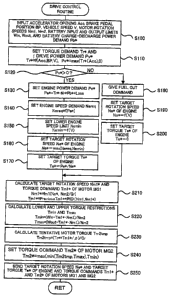
Fig. 2 is a flowchart showing a drive control routine
executed by a hybrid electronic control unit included in the
hybrid vehicle of Fig. I;
Fig. 3 shows one example of a torque demand setting map;
Fig. 4 shows one example of an engine speed demand setting
map;
Fig. 5 shows an operation line of an engine with a constant
curve of engine power demand Pe*;
Fig. 6 shows one example of a lower engine speed setting
map;
Fig. 7 is an alignment chart showing torque-rotation
speed dynamics of respective rotation elements of a power
distribution integration mechanism included in the hybrid
vehicle of Fig. 1;
CA 02558386 2006-08-29
WO 2006/009049 PCT/JP2005/012970
12
Fig. 8 schematically illustrates the configuration of
another hybrid vehicle in one modified example; and
Fig. 9 schematically illustrates the configuration of
still another hybrid vehicle in another modified example.
Best Modes of Carrying Out the Invention
One mode of carrying out the invention is discussed
below as a preferred embodiment. Fig. 1 schematically
illustrates the construction of a hybrid vehicle 20 with a power
output apparatus mounted thereon in one embodiment of the
invention. As illustrated, the hybrid vehicle 20 of the
embodiment includes an engine 22, a three shaft-type power
distribution integration mechanism 30 that is linked with a
crankshaft 26 functioning as an output shaft of the engine 22
via a damper 28, a motor MG1 that is linked with the power
distribution integration mechanism 30 and is capable of
generating electric power, a reduction gear 35 that is attached
to a ring gear shaft 32a functioning as a drive shaft connected
with the power distribution integration mechanism 30, another
motor MG2 that is linked with the reduction gear 35, and a hybrid
electronic control unit 70 that controls the whole power output
apparatus.
The engine 22 is an internal combustion engine that uses
a hydrocarbon fuel, such as gasoline or light oil, to output
power. An engine electronic control unit (hereafter referred
to as engine ECU) 24 receives signals from diverse sensors that
CA 02558386 2006-08-29
WO 2006/009049 PCT/JP2005/012970
13
detect operating conditions of the engine 22, and takes charge
of operation control of the engine 22, for example, fuel
injection control, ignition control, and intake air flow
regulation. The engine ECU 24 communicates with the hybrid
electronic control unit 70 to control operations of the engine
22 in response to control signals transmitted from the hybrid
electronic control unit 70 while outputting data relating to
the operating conditions of the engine 22 to the hybrid
electronic control unit 70 according to the requirements.
The power distribution and integration mechanism 30 has
a sun gear 31 that is an external gear, a ring gear 32 that is
an internal gear and is arranged concentrically with the sun
gear 31, multiple pinion gears 33 that engage with the sun gear
31 and with the ring gear 32, and a carrier 34 that holds the
multiple pinion gears 33 in such a manner as to allow free
revolution thereof and free rotation thereof on the respective
axes. Namely the power distribution and integration mechanism
30 is constructed as a planetary gear mechanism that allows for
differential motions of the sun gear 31, the ring gear 32, and
the carrier 34 as rotational elements. The carrier 34, the sun
gear 31, and the ring gear 32 in the power distribution and
integration mechanism 30 are respectively coupled with the
crankshaft 26 of the engine 22, the motor MG1, and the reduction
gear 35 via ring gear shaft 32a. While the motor MGl functions
as a generator, the power output from the engine 22 and input
through the carrier 34 is distributed into the sun gear 31 and
CA 02558386 2006-08-29
WO 2006/009049 PCT/JP2005/012970
14
the ring gear 32 according to the gear ratio. While the motor
MG1 functions as a motor, on the other hard, the power output
from the engine 22 and input through the carrier 34 is combined
with the power output from the motor MG1 and input through the
sun gear 31 and the composite power is output to the ring gear
32. The power output to the ring gear 32 is thus finally
transmitted to the driving wheels 63a and 63b via the gear
mechanism 60, and the differential gear 62 from ring gear shaft
32a.
Both the motors MG1 and MG2 are known synchronous motor
generators that are driven as a generator and as a motor . The
motors MGl and MG2 transmit electric power to and from a battery
50 via inverters 41 and 42. Power lines 54 that connect the
inverters 41 and 42 with the battery 50 are constructed as a
positive electrode bus line and a negative electrode bus line
shared by the inverters 41 and 42. This arrangement enables
the electric power generated by one of the motors MG1 and MG2
to be consumed by the other motor . Operations of both the motors
MG1 and MG2 are controlled by a motor electronic control unit
(hereafter referred to as motor ECU) 40. The motor ECU 40
receives diverse signals required for controlling the
operations of the motors MG1 and MG2, for example, signals from
rotational position detection sensors 43 and 44 that detect the
rotational positions of rotors in the motors MG1 and MG2 and
phase currents applied to the motors MG1 and MG2 and measured
by current sensors (not shown). The motor ECU 40 outputs
CA 02558386 2006-08-29
WO 2006/009049 PCT/JP2005/012970
switching control signals to the inverters 41 and 42. The motor
ECU 40 communicates with the hybrid electronic control unit 70
to control operations of the motors MGl and MG2 in response to
control signals transmittedfrom the hybrid electronic control
5 unit 70 while outputting data relating to the operating
conditions of the motors MG1 and MG2 to the hybrid electronic
control unit 70 according to the requirements.
The battery 50 is under control of a battery electronic
control unit (hereafter referred to as battery ECU) 52. The
10 battery ECU 52 receives diverse signals required for control
of the battery 50, for example, an inter-terminal voltage
measured by a voltage sensor (not shown) disposed between
terminals of the battery 50, a charge-discharge current
measured by a current sensor (not shown) attached to the power
I5 line 54 connected with the output terminal of the battery 50,
and a battery temperature measured by a temperature sensor (not
shown) attached to the battery 50. The battery ECU 52 outputs
data relating to the state of the battery 50 to the hybrid
electronic control unit 70 via communication according to the
requirements . The battery ECU 52 calculates a state of charge
(SOC) of the battery 50, based on the accumulated
charge-discharge current measured by the current sensor, for
control of the battery 50.
The hybrid electronic control unit 70 is constructed as
a microprocessor including a CPU 72, a ROM 74 that stores
processing programs, a RAM 76 that temporarily stores data, and
CA 02558386 2006-08-29
WO 2006/009049 PCT/JP2005/012970
16
a non-illustrated input-output port, and a non-illustrated
communication port. The hybrid electronic control unit 70
receives various inputs via the input port : an ignition signal
from an ignition switch 80, a gearshift position SP from a
gearshift position sensor 82 that detects the current position
of a gearshift lever 81, an accelerator opening Acc from an
accelerator pedal position sensor 84 that measures a step-on
amount of an accelerator pedal 83, a brake pedal position BP
from a brake pedal position sensor 86 that measures a step--on
amount of a brake pedal 85, and a vehicle speed V from a vehicle
speed sensor 88. The hybrid electronic control unit 70
communicates with the engine ECU 24 , the motor ECU 40 , and the
battery ECU 52 via the communication port to transmit diverse
control signals and data to and from the engine ECU 24, the motor
ECU 40, and the battery ECU 52, as mentioned previously.
said motor.
The hybrid vehicle 20 of the embodiment thus constructed
calculates a torque demand to be output to the ring gear shaft
32a functioning as the drive shaft, based on observed values
of a vehicle speed V and an accelerator opening Acc, which
corresponds to a driver ~ s step-on amount of an accelerator pedal
83. The engine 22 and the motors MG1 and MG2 are subjected to
operation control to output a required level of power
corresponding to the calculated torque demand to the ring gear
shaft 32a. The operation control of the engine 22 and the motors
MG1 and MG2 selectively effectuates one of a torque conversion
CA 02558386 2006-08-29
WO 2006/009049 PCT/JP2005/012970
17
drive mode, a charge-discharge drive mode, and a motor drive
mode. The torque conversion drive mode controls the operations
of the engine 22 to output a quantity of power equivalent to
the required level of power, while driving and controlling the
motors MG1 and MG2 to cause all the power output from the engine
22 to be subjected to torque conversion by means of the power
distribution integration mechanism 30 and the motors MG1 and
MG2 and output to the ring gear shaft 32a. The charge-discharge
drive mode controls the operations of the engine 22 to output
a quantity of power equivalent to the sum of the required level
of power and a quantity of electric power consumed by charging
the battery 50 or supplied by discharging the battery 50, while
driving and controlling the motors MGl and MG2 to cause all or
part of the power output from the engine 22 equivalent to the
required level of power to be subjected to torque conversion
by means of the power distribution integration mechanism 30 and
the motors MGl and MG2 and output to the ring gear shaft 32a,
simultaneously with charge or discharge of the battery 50 . The
motor drive mode stops the operations of the engine 22 and drives
and controls the motor MG2 to output a quantity of power
equivalent to the required level of power to the ring gear shaft
32a.
The description now regards the operations of the hybrid
vehicle 20 of the embodiment having the configuration discussed
above. Fig. 2 is a flowchart showing a drive control routine
executed by the hybrid electronic control unit 70 . This routine
CA 02558386 2006-08-29
WO 2006/009049 PCT/JP2005/012970
18
is carried out repeatedly at preset time intervals (for example,
at every several msec).
In the drive control routine, the CPU 72 of the hybrid
electronic control unit 70 first inputs various data required
for control, that is, the accelerator opening Acc from the
accelerator pedal position sensor 84, the brake pedal position
BP from the brake pedal position sensor 86, the vehicle speed
V from the vehicle speed sensor 88, rotation speeds Nml and Nm2
of the motors MGl and MG2, and an input limit Win, and an output
limit Wout, and a charge-discharge power demand Pb* of the
battery 50 (step 5100) . The rotation speeds Nml and Nm2 of the
motors MGl and MG2 are computed from the rotational positions
of the respective rotors in the motors MG1 and MG2 detected by
the rotational position detection sensors 43 and 44 and are
received from the motor ECU 40 by communication. The input
limit Win and the output limit Wout of the battery 50 are set
based on the temperature Tb of the battery 50 measured by the
temperature sensor 51 and the observed current state of charge
(SOC) of the battery 50 and are received from the battery ECU
52 by communication. The charge-discharge power demand Pb* of
the battery 50 is set based on the current state of charge (SOC)
of the battery 50 and is received from the battery ECU 52 by
communication.
After the data input, the CPU 72 sets a torque demand Tr*
to be output to the ring gear shaft 32a or the drive shaft linked
to the drive wheels 63a and 63b as the torque required for the
CA 02558386 2006-08-29
WO 2006/009049 PCT/JP2005/012970
19
vehicle and a drive power demand Pv* required to drive the hybrid
vehicle 20, based on the input accelerator opening Acc, the
input brake pedal position BP, and the input vehicle speed V
( step 5110 ) . A concrete procedure of setting the torque demand
Tr* in this embodiment stores in advance variations in torque
demand Tr* against the accelerator opening Acc, the brake pedal
position BP, and the vehicle speed V as a torque demand setting
map in the ROM 74 and reads the torque demand Tr* corresponding
to the given accelerator opening Acc, the given brake pedal
position BP, and the given vehicle speed V from the map. One
example of the torque demand setting map is shown in Fig. 3.
The drive power demand Pv* is set to the greater between a value
and the product of the torque demand Tr* , which depends on
the accelerator opening Acc, and a rotation speed Nr of the ring
gear shaft 32a. The rotation speed Nr of the ring gear shaft
32a is obtained by multiplying the vehicle speed V by a
conversion coefficient k or by dividing the rotation speed Nm2
of the motor MG2 by a gear ratio Gr of the reduction gear 35.
The drive power demand Pv* is then compared with the value
~0' (step 5120). When the drive power demand Pv* is equal to
0, the torque demand Tr* is either 0 or a negative value. This
means no requirement of power output from the engine 22 and thus
allows the engine 22 to be at a stop as described later. When
the drive power demand Pv* is greater than 0 at step 5120, power
output from the engine 22 is required. An engine power demand
Pe* to be output from the engine 22 is accordingly calculated
CA 02558386 2006-08-29
WO 2006/009049 PCT/JP2005/012970
as the sum of the product of the torque demand Tr* and the
rotation speed Nr of the ring gear shaft 32a, the
charge-discharge power demand Pb* of the battery 50, and a
potential loss (step 5130). An engine speed demand Nereq is
5 set as a rotation speed of the engine 22 at an efficient drive
point that ensures efficient output of the engine power demand
Pe* from the engine 22 (step 5140). A concrete procedure of
setting the engine speed demand Nereq in this embodiment stores
in advance a variation in engine speed demand Nereq against the
10 engine power demand Pe* as an engine speed demand setting map
in the ROM 74 and reads the engine speed demand Nereq
corresponding to the given engine power demand Pe* from the map.
One example of the engine speed demand setting map is shown in
Fig. 4. The efficient drive point of the engine 22 ( rotation
15 speedNe x torque Te) ensuring the efficient output of the engine
power demand Pe* may be expressed by an operation line in a
torque-rotation speed map as shown in Fig. 5. The combination
of the rotation speed and the torque at an intersection between
a curve of constant engine power demand Pe* (shown by the broken
20 line) and the operation line gives the efficient drive point
of the engine 22 ensuring the efficient output of the engine
power demand Pe*.
The CPU 72 subsequently sets a lower engine speed limit
Nemin as a rotation speed of the engine 22 at a specific drive
point that ensures efficient output of a required power from
the engine 22 for a constant-speed drive of the hybrid vehicle
CA 02558386 2006-08-29
WO 2006/009049 PCT/JP2005/012970
21
20 at the vehicle speed V (step 5150). A concrete procedure
of setting the lower engine speed limit Nemin in this embodiment
stores in advance a variation in lower engine speed limit Nemin
against the vehicle speed V as a lower engine speed limit setting
map in the ROM 74 and reads the lower engine speed limit Nemin
corresponding to the given vehicle speed V from the map . One
example of the lower engine speed limit setting map is shown
in Fig. 6. A reference vehicle speed Vref shown in Fig. 6 is
set as a criterion for determining requirement of intermittent
operations of the engine 22.
The CPU 72 then sets the greater between the engine speed
demand Nereq and the lower engine speed limit Nemin to a target
rotation speed Ne* of the engine 22 (step 5160), and divides
the engine power demand Pe* by the target rotation speed Ne*
to calculate a target torque Te* of the engine 22 (step S170) .
Setting the greater between the engine speed demand Nereq and
the lower engine speed limit Nemin to the target rotation speed
Ne* of the engine 22 aims to assure a quicker response to an
abrupt increase in engine power demand Pe*. In one example,
the driver may step on the accelerator pedal 83 in a decelerating
state with some decrease (but not to the zero level) in drive
power demand Pv*, while the hybrid vehicle 20 runs at a
relatively high speed. Under such conditions, the engine speed
demand Nereq is lower than the lower engine speed limit Nemin.
In general, the engine power increase by only a torque rise is
attained within a shorter time period than the engine power
CA 02558386 2006-08-29
WO 2006/009049 PCT/JP2005/012970
22
increase by only a rotation speed rise. This is ascribed to
the less time required for increasing the intake air flow and
the amount of fuel injection than the time required for
increasing the rotation speed of the rotational system of the
engine 22 . Namely the engine 22 driven at the lower engine speed
limit Nemin, which is higher than the engine speed demand Nereq,
has a quicker response to a demand for output power increase
from the engine 22.
The CPU 72 subsequently calculates a target rotation
speed Nm1* of the motor MG1 from the target rotation speed Ne*
of the engine 22, the rotation speed Nr (= Nm2/Gr) of the ring
gear shaft 32a, and a gear ratio p of the power distribution
integration mechanism 30 according to Equation (1) given below,
while calculating- a torque command Tml* of the motor MGl from
the calculated target rotation speed Nml* and the current
rotation speed Nml of the motor MG1 according to Equation (2)
given below (step 5210):
Nml* = Ne*~ (1+p) /p - Nm2/ (Gr~p) (1)
Tml* = Previous Tml* + kl(Nml*-Nml) + k2J(Nml*-Nml)dt (2)
Equation (1) is a dynamic relational expression of the rotation
elements included in the power distribution integration
mechanism 30. Fig. 7 is an alignment chart showing
torque-rotation speed dynamics of the respective rotation
elements included in the power distribution integration
CA 02558386 2006-08-29
WO 2006/009049 PCT/JP2005/012970
23
mechanism 30 . The left axis ' S' represents the rotation speed
of the sun gear 31 that is equivalent to the rotation speed Nml
of the motor MGl. The middle axis ' C' represents the rotation
speed of the carrier 34 that is equivalent to the rotation speed
Ne of the engine 22 . The right axis ' R' represents the rotation
speed Nr of the ring gear 32 that is obtained by multiplying
the rotation speed Nm2 of the motor MG2 by the gear ratio Gr
of the reduction gear 35. Equation (1) is readily introduced
from this alignment chart of Fig. 7. Two thick arrows on the
axis ' R' respectively show a torque that is transmitted to the
ring gear shaft 32a when the torque Te*. is output from the engine
22 in steady operation at a specific drive point of the target
rotation speed Ne* and the target torque Te*, and a torque that
is applied to the ring gear shaft 32a via the reduction gear
35 when a torque Tm2* is output from the motor MG2. Equation
(2) is a relational expression of feedback control to drive and
rotate the motor MGl at the target rotation speed Nm1*. Tn
Equation (2) given above, 'kl' in the second term and 'k2' in
the third term on the right side respectively denote a gain of
the proportional and a gain of the integral term.
After calculation of the target rotation speed Nml* and
the torque command Tml* of the motor MG1, the CPU 72 calculates
a lower torque restriction Tmin~and an upper torque restriction
Tmax as minimum and maximum torques output from the motor MG2
according to Equations (3) and (4) given below (step 5220):
CA 02558386 2006-08-29
WO 2006/009049 PCT/JP2005/012970
24
Turin = (Win - Tml*~Nml) / Nm2 (3)
Tmax = (Wout - Tml*~Nm1) / Nm2 (4)
The lower torque restriction Turin and the upper torque
restriction Tmax are respectively given by dividing a
difference between the input limit Win of the battery 50 and
power consumption (power generation) of the motor MG1, which
is the product of the torque command Tml* and the input current
rotation speed Nml of the motor MG1, and a difference between
the output limit Wout of the battery 50 and the power consumption
(power generation) of the motor MGl by the input current
rotation speed Nm2 of the motor MG2 . The CPU 72 then calculates
a tentative motor torque Tm2tmp to be output from the motor MG2
from the torque demand Tr*, the torque command Tml* of the motor
MGl, the gear ratio p of the power distribution integration
mechanism 30, and the gear ratio Gr of the reduction gear 35
according to Equation (5) given below (step 5230):
Tm2tmp = (Tr* + Tm1* / p) / Gr (5)
The CPU 72 limits the tentative motor torque Tm2tmp to the range
between the calculated lower torque restriction Turin and upper
torque restriction Tmax to set a torque command Tm2* of the motor
MG2 (step 5240) . Setting the torque command Tm2* of the motor
MG2 in this manner restricts the torque demand Tr* to be output
to the ring gear shaft 32a or the drive shaft within the range
CA 02558386 2006-08-29
WO 2006/009049 PCT/JP2005/012970
between the input limit Win and the output limit Wout of the
battery 50. Equation (5) is readily introduced from the
alignment chart of Fig. 7.
The CPU 72 sends the target rotation speed Ne* and the
5 target torque Te* of the engine 22 to the engine ECU 24, while
sending the torque commands Tm1* and Tm2* of the motors MG1 and
MG2 to the motor ECU 40 (step 5250), before exiting from the
drive control routine. The engine ECU 24 receives the target
rotation speed Ne* and the target torque Te* and executes fuel
10 injection control and ignition control of the engine 22 to drive
the engine 22 at the specified drive point of the target rotation
speed Ne* and the target torque Te* . The motor ECU 40 receives
the torque commands Tml* and Tm2* and executes switching control
of the switching elements included in the respective inverters
15 41 and 42 to drive the motor MG1 with the torque command Tml*
and the motor MG2 with the torque command Tm2*.
When it is determined at step 5120 that the drive power
demand Pv* is equal to 0 at step 5120, the CPU 72 specifies no
requirement of power output from the engine 22 and gives a
20 command of cutting the fuel supply to the engine 22 (step 5180) .
According to a concrete procedure, the hybrid electronic
control unit 70 sends a fuel cut control signal to the engine
ECU 24 via the communication port . The CPU 72 subsequently sets
the lower engine speed limit Nemin, which is read corresponding
25 to the vehicle speed V from the lower engine speed limit setting
map as described above, to the target rotation speed Ne* of the
CA 02558386 2006-08-29
WO 2006/009049 PCT/JP2005/012970
26
engine 22 (step 5190) , and sets the torque command Te* of the
engine 22 equal to 0 (step 5200) . The CPU 72 then executes the
processing of steps 5210 to 5240 to set the torque commands Tml*
and Tm2* of the motors MG1 and MG2 and sends the settings to
the engine ECU 24 and to the motor ECU 40 (step 5250), before
exiting from the drive control routine. When the vehicle speed
V is lower than the reference vehicle speed Vref, the lower
engine speed limit Nemin is set equal to 0. The engine 22 is
accordingly stopped without rotations.
The driver may step on the accelerator pedal 83 in an
accelerator-off state, while the hybrid vehicle 20 runs at a
relatively high speed. In the accelerator-off state, the drive
power demand Pv* is equal to 0. The engine 22 accordingly has
a fuel cut and is rotated at the lower engine speed limit Nemin.
The driver ~ s depression of the accelerator pedal 83 under such
conditions cancels the fuel cut and immediately resumes the
intake air flow and the fuel injection to output the torque from
the engine 22. The engine 22 is rotated at the lower engine
speed limit Nemin, which causes the engine 22 to efficiently
output a required power for a constant-speed drive of the hybrid
vehicle 20 at the current vehicle speed V. Simple adjustment
of the intake air flow and the amount of fuel injection
immediately enables the engine 22 to efficiently output the
required power for a constant-speed drive of the hybrid vehicle
20 . The drive point of the engine 22 changes along the operation
line (see Fig. 5), which represents continuation of efficient
CA 02558386 2006-08-29
WO 2006/009049 PCT/JP2005/012970
27
engine drive points, from the specific drive point that enables
the engine 22 to efficiently output the required power for a
constant-speed drive. This control ensures a quicker response
of the engine 22 to output the required power, compared with
the conventional control of driving the engine 22 at a low
rotation speed or stopping the engine 22 . In the configuration
of the hybrid vehicle 20 of the embodiment, as clearly shown
by the setting of the tentative motor torque Tm2tmp at step 5230,
the output torque of the motor MG2 driven with the electric power
supply from the battery 50 compensates for a delayed response
of the engine 22. The quick output of the required power from
the engine 22 reduces the discharge electric power of the
battery 50 and desirably decreases the loading of the battery
50. This arrangement.thus effectively prevents premature
deterioration of the battery 50, which is accelerated by
repeated charges and discharges of relatively high electric
powers.
As described above, the hybrid vehicle 20 of the
embodiment drives the engine 22 at the rotation speed of not
lower than the lower engine speed limit Nemin corresponding to
the vehicle speed V, so as to enhance the response of the engine
22 to a change in output power demand. The control of the
embodiment desirably reduces an insufficiency of the required
driving power due to a delayed response of the engine 22 , thus
lowering the required discharge level of the battery 50 and
reducing the load of the battery 50. The lowered charge and
CA 02558386 2006-08-29
WO 2006/009049 PCT/JP20051012970
28
discharge levels desirably prevent premature deterioration of
the battery 50, which is accelerated by repeated charges and
discharges at relatively high electric power levels. The
quicker response of the engine 22 also ensures a prompt shift
of the drive point of the engine 22 to the efficient engine drive
points along the operation line. In the case of no requirement
of power output from the engine 22 with the drive power demand
Pv* equal to 0, the control procedure of the embodiment stops
the fuel injection to the engine 22 and thus desirably improves
the fuel consumption.
The hybrid vehicle 20 of the embodiment sets the lower
engine speed limit Nemin to the specific rotation speed of the
engine 22 at the specific drive point that ensures efficient
output of the required power for a constant-speed drive of the
I5 hybrid vehicle 20 on the flat road surface at the vehicle speed
V. This rotation speed level is, however, not essential, and
the lower engine speed limit Nemin may be set to be slightly
lower or slightly higher than the specific rotation speed at
the specific drive point.
The hybrid vehicle 20 of the embodiment sets the greater
between the value ' 0' and the product of the torque demand Tr*,
which depends on the accelerator opening Acc, and the rotation
speed Nr of the ring gear shaft 32a, to the drive power demand
Pv* . One possible modification may set the drive power demand
Pv* to the product of the torque demand Tr*, which depends on
the accelerator opening Acc, and the rotation speed Nr of the
CA 02558386 2006-08-29
WO 2006/009049 PCT/JP2005/012970
29
ring gear shaft 32a, to the drive power demand Pv*. Another
possible modification may set the drive power demand Pv* to the
torque demand Tr*, which depends on the brake pedal position
BP. In such modified structures, the fuel cut control depends
on whether the drive power demand Pv* is a positive level or
not.
The hybrid vehicle 20 of the embodiment drives the engine
22 in response to the drive power demand Pv* of higher than 0,
while cutting off the fuel supply to the engine 22 in response
to the drive power demand Pv* equal to 0. One possible
modification may drive the engine 22 in response to the drive
power demand Pv* of higher than a preset threshold value Pref
(greater than 0) , while cutting off the fuel supply to the engine
22 in response to the drive power demand Pv* of lower than the
preset threshold value Pref.
In the hybrid vehicle 20 of the embodiment, the power of
the motor MG2 is subjected to gear change by the reduction gear
35 and is output to the ring gear shaft 32a. In one possible
modification shown as a hybrid vehicle 120 of Fig. 8, the power
of the motor MG2 may be output to another axle (that is, an axle
linked with wheels 64a and 64b) , which is different from an axle
connected with the ring gear shaft 32a (that is, an axle linked
with the wheels 63a and 63b).
In the hybrid vehicle 20 of the embodiment, the power of
the engine 22 is output via the power distribution integration
mechanism 30 to the ring gear shaft 32a functioning as the drive
CA 02558386 2006-08-29
WO 2006/009049 PCT/JP2005/012970
shaft linked with the drive wheels 63a and 63b. In another
possible modification of Fig. 9, a hybrid vehicle 220 may have
a pair-rotor motor 230, which has an inner rotor 232 connected
with the crankshaft 26 of the engine 22 and an outer rotor 234
5 connected with the drive shaft for outputting the power to the
drive wheels 63a, 63b and transmits part of the power output
from the engine 22 to the drive shaft while converting the
residual part of the power into electric power.
The embodiment discussed above is to be considered in all
10 aspects as illustrative and not restrictive. There may be many
modifications, changes, and alterations without departing from
the scope or spirit of the main characteristics of the present
invention. The scope and spirit of the present invention are
indicated by the appended claims, rather than by the foregoing
15 description.
Industrial Applicability
The technique of the invention is desirably applicable
to manufacturing industries of hybrid vehicles and power output
20 apparatuses.