Note: Descriptions are shown in the official language in which they were submitted.
CA 02564606 2006-10-25
WO 2005/118151 PCT/US2005/018947
ANTISTATIC PAINT CUP
BACKGROUND OF THE INVENTION
The present invention is directed generally to a fluid supply cup for a fluid
applicator, and more particularly to a fluid supply cup having antistatic
properties.
Some fluid applicators, such as gravity feed spray guns, have a fluid supply
cup
mounted on top of the fluid applicator. The fluid supply cup can have a
disposable liner.
Fluid, such as paint or other coatings, can be measured and mixed in a
separate container,
and then poured into the disposable liner for use, or it can be measured and
mixed in the
disposable liner itself. Disposable liners can reduce the time and cost of
cleanup.
However, when disposable liners are used with certain types of coatings having
a
chargeable ingredient, for example, paint containing metallic particles, the
uniformity of
the coating can change during the application process. The resulting parts
have non-
uniform coatings. Some users have begun to recommend that disposable liners
not be
used with certain types of coatings because of the problems that can result
from the non-
uniform coating.
SUMMARY OF THE INVENTION
Therefore, there remains a need for a fluid supply cup which will not affect
the
uniformity of the coating being dispensed.
The present invention meets this need by providing a flexible, disposable cup
for
use in a fluid supply assembly. The disposable cup is made of an antistatic
material.
chargeable particles in the coating mixture do not stick to the disposable cup
so that the
uniformity of the coating mixture is maintained while it is dispensed. By
"antistatic
material," we mean the material has the ability to prevent the build-up of
electrostatic
charges. The term "antistatic material" is intended to include conventional
antistatic
materials, as well as static dissipative materials, i.e., materials which have
the ability to
1
CA 02564606 2011-06-29
discharge static charges at a rate higher than typical antistatic additives ,
and conductive
materials, which have the ability to discharge electrostatic charges rapidly.
In a broad aspect, the present invention pertains to a fluid supply assembly
comprising a reusable plastic cup holder, a lid having an opening therein, and
a flexible,
disposable cup positioned in the reusable cup holder. The disposable cup
comprises a
side wall, an open outlet end, and a closed bottom defining an interior. The
disposable
cup is see through, the disposable cup collapsing as the fluid is dispensed.
The lid covers
the open outlet end of the disposable cup, the disposable cup comprising a
polymeric
material containing an antistatic additive. The antistatic additive prevents
chargeable
particles in a coating mixture from sticking to the disposable cup so that
uniformity of
the coating mixture is maintained while it is dispensed.
In a still further aspect, the present invention provides a method of
maintaining
uniformity of a coating mixture during dispensing comprising providing a
reusable cup
holder and an outer lid having an opening therein, the reusable cup holder
adapted to
mate with the outer lid, and providing a disposable cup adapted to fit in the
reusable cup
holder. The disposable cup comprises a side wall, an open outlet end, and a
closed
bottom defining an interior. The method comprehends the disposable cup
comprising an
antistatic material, filling the disposable cup with a coating mixture
containing chargeable
particles, placing the disposable cup in the reusable cup holder, attaching
the outer lid to
the reusable cup holder, sealing the disposable cup within the reusable cup
holder and the
outer lid, and dispensing the coating mixture, whereby the chargeable
particles in the
coating mixture do not stick to the disposable cup so that uniformity of the
coating
mixture is maintained while it is dispensed.
2
CA 02564606 2011-06-29
BRIEF DESCRIPTION OF THE DRAWINGS
Fig. 1 is side elevation view of a gravity-feed paint sprayer with a fluid
supply
assembly.
Fig. 2 is an exploded side sectional view of one embodiment of a fluid supply
assembly.
Fig. 3 is partial side sectional view of the assembled connection between the
reusable cup holder and reusable outer lid.
Fig. 4 is a partial side sectional view of an alternate embodiment of the
reusable
outer lid showing stacking of the fluid supply assemblies.
Fig. 5 is a side sectional view of an alternate embodiment of the disposable
lid.
Fig. 6 is an assembled side sectional view of the alternate embodiment of the
disposable lid of Fig. 5 and the disposable cup.
Fig. 7 is a side sectional view of an alternate embodiment of the disposable
cup.
Fig. 8 is a top view of an alternate embodiment of the disposable cup.
Fig. 9 is a side sectional view of the disposable cup of Fig. 8 is another
axis.
Fig. 10 is a side sectional view of the disposable cup of Fig. 8 in another
axis.
Fig. 11 is a partial assembled side sectional view of the connection between
one
embodiment of an adapter and the reusable outer lid.
2a
CA 02564606 2010-07-23
Fig. 12 is a top view of the adapter of Fig. 11.
Fig. 13 is a top view of the assembled connection of Fig. 11 before rotation
(without the filter).
Fig. 14 is a perspective view of a reusable outer lid.
Fig. 15 is a top view of the assembled connection of Fig. 11 after rotation
(without
the filter).
DETAILED DESCRIPTION OF THE INVENTION
A fluid supply assembly attached to a fluid applicator is shown in Fig. 1. In
one
embodiment, the fluid supply assembly is for feeding liquid, such as paint or
other coating,
to the fluid applicator, such as a paint sprayer. The present invention will
be described for
a paint sprayer, such as a gravity feed paint sprayer, for use in applying
paint to coat
substrate surfaces. The paint sprayer can be used in the automotive
refinishing market,
such as automobile body shops, for repainting automobiles. Although the fluid
supply
assembly is described for a paint sprayer, it is not limited to such use. It
can be used for
supplying other flowable liquids containing chargeable particles.
Referring to Fig. 1, a paint sprayer 10 is shown. It includes a body 15, a
nozzle
assembly 20 secured to a front end 25 of body 15, and a handle 30 depending
from a rear
end 35 ofbody 15. A trigger 40 is pivotally secured to body 15 for the manual
actuation
of sprayer 10. A top-mounted paint supply assembly 45 is mounted to body 15
near front
end 25 for feeding paint to nozzle assembly 20. An air connector 50 is
connected to an air
hose (not shown) for the delivery of pressurized air to nozzle assembly 20,
wherein the
delivery of pressurized air is controlled by trigger 40.
Compressed air from air connector 50 is delivered through an internal passage
(not
shown) to nozzle assembly 20 and the compressed air acts to atomize paint and
deliver it
through nozzle assembly 20 to spray paint about paint axis 54. Paint is
delivered to nozzle
assembly 20 from paint supply assembly 45.
3
CA 02564606 2006-10-25
WO 2005/118151 PCT/US2005/018947
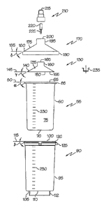
Figs. 1-3 show one embodiment of paint supply assembly 45. The paint supply
assembly includes disposable cup 55. Disposable cup 55 has a side wall 60
which is
generally cylindrical. The outlet end 65 at the top of the cup is open, and
the bottom 70 is
closed. The side wall 60, outlet end 65, and bottom 70 define an interior 75.
Disposable fluid supply cups can develop a static charge during use. As a
result, if
the coating contains chargeable particles, the particles are attracted to the
walls of the cup.
As the chargeable particles stick to the cup, the coating composition changes.
This results
in a change in the uniformity of the coating being applied during the
application process,
making uniform application difficult, if not impossible. For example, the
coating could be
a paint mixture containing metallic particles. As the paint is being applied,
the metallic
particles can stick to the walls of the fluid supply cup. When this happens,
the color of the
paint being applied changes, and article being painted has a non-uniform
color.
The disposable cup of the present invention is made of an antistatic material,
which
dissipates the static charge which can develop during manufacture, storage,
and use.
Because the static charge is dissipated, the chargeable particles in the
coating mixture do
not stick to the disposable cup during spraying. Therefore, the uniformity of
the coating
mixture is maintained during dispensing. Chargeable particles include but are
not limited
to, metallic particles and non-metallic particles.
Generally, the antistatic material comprises a polymeric material containing
an
antistatic additive. Suitable polymeric materials include, but are limited to,
polyethylene,
polypropylene, or other soft, flexible polymer. The polymeric material can
optionally be a
substantially transparent polymeric material, or it can be translucent or even
opaque, if
desired.
The term "antistatic additive" is intended to include typical antistatic
additives,
static dissipative additives, and conductive additives. Antistatic agents can
be
incorporated into the polymer before molding (internal) or applied to the
surface after
molding (external). Some function by being inherently conductive, while others
function
by absorbing moisture from the atmosphere.
4
CA 02564606 2006-10-25
WO 2005/118151 PCT/US2005/018947
Conventional antistatic materials have a resistivity generally between about
109
and 1012 ohms per square. The antistatic materials can be surface resistive,
surface-coated,
or filled throughout. With typical antistatic materials, the rate at which the
charges are
dissipated is often dependent on atmospheric conditions, such as relative
temperature and
humidity.
Static dissipative materials have the ability to discharge static charge at a
greater
rate than typical antistatic materials. Static dissipative materials have a
resistivity
generally between about 106 and 109 ohms per square. Static dissipative
materials can be
surface-coated or filled throughout. Static dissipative materials may be
affected by
atmospheric conditions.
Conductive materials have the ability to discharge electrostatic charges
rapidly.
Conductive materials have a resistivity generally between about 103 and 106
ohms per
square. These materials are generally filled throughout. Electrostatic charges
flow
through the impregnated material. Atmospheric conditions do not affect
conductive
materials.
Suitable antistatic additives include, but are not limited to, long-chain
aliphatic
amines and amides, phosphates, quaternary ammonium compounds, polyethylene
glycols,
glycol esters, ethoxylated long-chain aliphatic amines, polymeric antistatic
additives
composed of hydrophilic copolymers, intrinsic conductive polymers, such as
polyaniline
and polythiophene, and conductive fillers, such as carbon black, metal powder
and fibers,
and graphite fibers.
In use, the disposable cup made of antistatic material is filled with a
coating
mixture containing chargeable particles. The disposable cup is placed in the
reusable cup
holder, and the outer lid is attached to the reusable cup holder. This seals
the disposable
cup within the reusable cup holder and the outer lid. The coating mixture is
then
dispensed. The chargeable particles in the paint mixture do not stick to the
disposable cup
so that the uniformity of the coating mixture is maintained while it is being
dispensed.
The disposable cup can have flexible side walls which allow the disposable cup
to
collapse as paint is dispensed. The side walls can be thin, for example in the
range of
about 0.003 in. to about 0.008 in. In one arrangement, the disposable cup can
have
5
CA 02564606 2006-10-25
WO 2005/118151 PCT/US2005/018947
flexible side walls which are designed to allow the disposable cup to collapse
with a
minimum of folds using almost all of the paint. The side walls adjacent to the
outlet end
and the bottom are thicker than the middle portion of the sidewall. With this
arrangement,
the cup appears almost to roll inside out as it collapses. The sidewalls
adjacent to the
outlet end and the bottom can be about two to about three times thicker than
the walls in
the center. For example, the sidewalls adjacent to the outlet end and the
bottom can be
about 0.006 in. to about 0.015 in., while the center portion is about 0.003
in. to about
0.005 in. The thicker portions adjacent to the outlet end and the bottom can
cover about '/4
of the sidewall, if desired. However, one of skill in the art will understand
that other
thickness can be used, as well as other ratios for the thicker portions.
The bottom can be slightly thicker, in the range of about 0.003 to about 0.02
in., so
that the bottom will remain substantially flat as the side walls collapse, if
desired. No air
vent is needed in the disposable cup because the side walls collapse. This
allows the user
to discharge the paint sprayer at any angle without leaks and to use more of
the paint in the
cup than is possible with conventional gravity feed paint cups.
In one embodiment, the outlet end 65 of the disposable cup 55 defines an axis
80.
There is a flange 85 extending outward and downward from the edge of the
outlet end 65.
The flange 85 extends downward at an angle a in a range of from about 10 to
about 70
from the axis 80 of the outlet end 65.
Reusable cup holder 90 is generally cylindrical. It has a side wall 95, an
open
upper end 100, and a lower end 105. The lower end 105 has an opening 110 in
it. The
opening 110 can cover all or almost all of the lower end 105, if desired.
Alternatively, the
lower end 105 could have one or more smaller openings. The opening 110 in the
lower
end 105 allows ambient air pressure to help the disposable cup collapse during
use.
Optionally, the reusable cup holder 90 can include one or more legs 112
extending
downward from the lower end 105. The legs can extend all of the way around the
opening
110 (i.e., a circular rib) or only a part of the way around the opening 110.
The legs 112
can assist in stacking the fluid supply assemblies as described below.
6
CA 02564606 2006-10-25
WO 2005/118151 PCT/US2005/018947
The upper end 100 defines an axis 115. A flange 120 extends outward and
downward from an edge of the upper end 100. The flange 120 extends downward at
an
angle i in a range of from about 10 to about 70 from the axis 115 of the
upper end 100.
The angle P is substantially the same as the angle a of the flange 85 of
disposable cup 55.
When the disposable cup 55 is placed in the reusable cup holder 90, the flange
120 of
reusable cup holder 90 supports the flange 85 of the disposable cup 55.
There is a connecting surface 125 at the upper end 100 of the reusable cup
holder
90. The connecting surface 125 can be on the sidewall, extend out from the
side wall, or it
can extend outward from the end of the flange 120, if desired.
The reusable cup holder 90 can be made of a rigid plastic, including, but not
limited to, polypropylene or high density polyethylene. Desirably, the plastic
selected is
strong enough that the reusable cup holder can withstand the clamping force of
a paint
shaker machine. The plastic is desirably transparent or translucent, although
it could be
opaque. If an opaque plastic is used, the side wall should have elongated
openings in it so
that the disposable cup and its contents can be seen. Typically, the walls can
be in the
range of from about 0.02 in. to about 0.08 in. thick.
The disposable lid 130 has a generally frustoconical portion 135. The outer
edge
140 of the generally frustoconical portion 135 defines an axis 145. The angle
y of the
outer edge 140 of the generally frustoconical portion 135 is in a range of
from about 10 to
about 70 from the axis 145. The angle 7 is substantially the same as the
angle a of the
flange 85 of disposable cup 55. The disposable lid 130 fits over the
disposable cup 55,
and the edge 140 of the disposable lid 130 mates with the flange 85 of the
disposable cup
55. The inside of the disposable lid 130 can have a downward extending rib
150, if
desired. The downward extending rib 150 extends into the interior 75 of the
disposable
cup and mates with the inside of the side wall 60 of the disposable cup 55,
forming a seal.
Additionally, there can be a downwardly projecting sealing bead 155 on the
inside of the
disposable lid 130. The downwardly projecting sealing bead 155 mates with the
flange 85
of the disposable cup 55 to aid in forming a seal.
7
CA 02564606 2006-10-25
WO 2005/118151 PCT/US2005/018947
There is a fitting 160 integrally connected to the generally fiustoconical
portion
135. The fitting 160 has an opening 165 extending through it.
The disposable lid 130 can be made of a transparent, translucent, or opaque
plastic.
Suitable plastics include, but are not limited to, polypropylene or high
density
polyethylene.
The reusable outer lid 170 has a generally frustoconical portion 175. The
outer
edge 180 of the generally fiustoconical portion 175 defines an axis 185. The
angle 5 of
the outer edge 180 of the generally frustoconical portion 175 is in a range of
from about
10 to about 70 from the axis 185. The angle 6 is substantially the same as
the angle R of
the flange 120 of reusable cup holder 90. The outer edge 180 of the reusable
outer lid 170
mates with the flange 120 of the reusable cup holder 90. There is a
complementary
connecting surface 190 at the outer edge 180 of the reusable outer lid 170. In
this
embodiment, the complementary connecting surface 190 extends downward from the
outer edge 180, although other arrangements are possible. The complementary
connecting
surface 190 mates with the connecting surface 125 of the reusable cup holder
90 to seal
the reusable cup holder 90 and reusable outer lid 170 together.
The reusable outer lid has a fitting 195 integrally connected to the generally
frustoconical portion 175. The fitting 195 has an opening 200 extending
through it. The
fitting 160 of the disposable lid 130 fits into the fitting 195 of the
reusable outer lid 170.
The reusable outer lid 170 can be made of a strong, tough plastic. Desirably,
the
plastic selected is strong enough that the reusable outer lid can withstand
the clamping
force of a paint shaker machine. Examples of suitable plastic include, but are
not limited
to, acetal. Acetal is not typically transparent. The reusable outer lid 170
can include one
or more sight holes so that the paint level is visible to the user, if
desired. The sight hole
can also allow the user to write the name of the name of the paint type on the
disposable
lid, and it permits easy removal of the disposable lid from the reusable outer
lid.
A conduit 210 connects the fluid supply assembly to the paint sprayer 10. The
conduit 210 mates with the fitting 195 of the reusable outer lid 170 and the
fitting 160 of
8
CA 02564606 2006-10-25
WO 2005/118151 PCT/US2005/018947
the disposable lid 130. The conduit 210 has an opening 215 through it. There
is a path for
fluid to flow from the interior 75 of the disposable cup 55 through the
opening 165 in the
disposable lid 130 through the opening 215 in conduit 210 to the paint sprayer
10. An
optional filter 220 can be placed into the opening 215 in the conduit 210, the
opening 200
in the reusable outer lid 170, or the opening 165 in the disposable lid 130 to
filter out
impurities.
In order to use the fluid supply assembly, the disposable cup 55 is placed
into the
reusable cup holder 90. The flange 85 of the disposable cup 55 mates with the
flange 120
of the reusable cup holder 90. The flange 85 centers the disposable cup 55 in
the reusable
cup holder 90.
Optionally, there can be indicia 230 on either the disposable cup 55 or the
reusable
cup holder 90 or both. The indicia 230 can be molded in the side, printed on
the side, a
label can be attached to the side, or the indicia can be supplied in some
other fashion. The
indicia 230 can be used to measure paint components. Alternatively, the
disposable cup
and reusable cup holder can be used on a scale, or with a measuring stick to
measure the
paint components.
The indicia can include mixing scales with one or more mixing ratios, e.g.,
4:1
mixing ratio, 2:1 mixing ratio; 3:2:1 mixing ratio, etc. Each mixing ratio
might include
one or more different sized divisions so that different amounts of fluid could
be measured
using each mixing ratio. The indicia can also include one or more universal
scales, i.e.,
scales with equal sized divisions. One universal scale might have 20 equal
divisions,
another 10 equal divisions, a third 5 equal divisions. There can be as many
universal
scales as needed. The multiple universal scales allow the user to measure
different
amounts of fluid without using the mixing ratio scales, which would not have
to be
included. The user could select the appropriate universal scale based on the
amount of
fluid needed.
Alternatively, the measuring guide could have indicia printed on a clear,
thin, flat,
plastic sheet. The plastic sheet has connecting parts on opposite sides of the
sheet,
including, but not limited to, tabs and slots. The plastic sheet is formed
into a cylinder,
9
CA 02564606 2006-10-25
WO 2005/118151 PCT/US2005/018947
and the tabs are inserted into the slots. The measuring guide can be placed on
the table,
and the disposable cup, or the reusable cup holder with the disposable cup in
it, can be
placed inside the cylinder. After the paint components are measured, the
disposable cup
(and the reusable cup holder if present) is removed from the cylinder. This
can be done by
lifting the disposable cup by the flange, or by disconnecting the tabs and
slots on the sheet.
Optional removal tabs on the flange 180 degrees apart can assist in removing
the
disposable cup. The disposable cup can then be placed in the reusable cup
holder (if not
already there). This measuring guide improves visibility and accuracy in
measuring the
paint components. The rectangular shape is easy to manufacture. It eliminates
the
necessity for accurate placement of a label on the disposable cup or reusable
cup holder. It
also allows more direct viewing of the indicia than with the label (i.e.,
through the label,
the reusable cup holder, and the disposable cup). It is particularly
advantageous when a
smaller diameter disposable cup is used because the indicia can be placed
right next to the
disposable cup. Finally, if the disposable cup is used alone, the reusable cup
holder stays
cleaner because it is not used when pouring and measuring paint.
The sheets may be formed in different sizes so that the measuring guides can
be
used with different sizes of disposable cups. A larger sheet could be used
with the
reusable cup holder and/or the larger disposable cup. The cylinder formed by
the larger
sheet is big enough so that the reusable cup holder and/or the larger
disposable cup fit
inside. The larger sheet could include a marking, such as a dotted line near
the bottom, to
allow proper alignment of the indicia depending whether the larger disposable
cup is used
with the reusable cup holder or not. The entire sheet might be used when the
larger
disposable cup is used with a reusable cup holder having legs. When the larger
disposable
cup is used alone (or the reusable cup does not affect the alignment, e.g.
because it does
not have legs), the sheet could be cut at the marking. This allows proper
alignment in
either situation. A smaller sheet could be used when a smaller disposable cup
is used.
The reusable cup holder would not generally be used with the smaller
disposable cup
when measuring fluid in order to provide proper alignment of the indicia and
the smaller
disposable cup.
After the disposable cup 55 is filled with paint, the disposable lid 130 is
placed on
top of the disposable cup 55. The angle y of the edge 140 of disposable lid
130 is
CA 02564606 2010-07-23
substantially the same as the angle a of the flange 85 of disposable cup 55 so
that the edge
140 of disposable lid 130 mates with the flange 85 of the disposable cup 55.
The angle y
centers the disposable lid 130 on the disposable cup 55. The angle y of the
disposable lid
130 also allows for additional sealing area without an increase in the overall
outside
diameter of the fluid supply assembly.
The downward extending rib 150 on the inside of the disposable lid 130 fits
inside
the disposable cup 55. There can be one or more downward extending ribs 150
around the
disposable lid 130 which extend part way around the inside of the disposable
lid 130,
or the rib can extend all the way around. The downward extending rib 150 keeps
the
disposable lid 55 in place, and it can also act as a seal. The disposable lid
130 can
also have a downwardly extending sealing head 155 which contacts the flange 85
of
the disposable cup 55 to improve sealing.
The reusable outer lid 170 is placed on top of the disposable lid 130. It is
tightened
to the reusable cup holder 90 using the connecting surface 125 of the reusable
cup holder
90 and the complementary connecting surface 190 of the reusable outer lid 170.
Suitable
connecting surfaces and complementary connecting surfaces include, but are not
limited
to, threaded connections, lugs and grooves, and pins and slots.
The outer edge 180 of the reusable outer lid 170 has an angle S which is
substantially the same as the angle R of the flange 120 of reusable cup holder
90. The
tightening of the reusable outer lid 170 to the reusable cup holder 90 clamps
the edge 140
of disposable lid 130 and flange 85 of disposable cup 55 together between edge
180 of
reusable outer lid 170 and flange 120 of reusable cup holder 90. The angle
increases the
clamping force without an increase in torque.
The angles a of the flange 85 of disposable cup 55, y of the edge 140 of
disposable
lid 130, R of flange 120 of reusable cup holder 90, and 8 of edge 180 of
reusable outer lid
170 are generally in the range of about 10 to about 70 from the respective
axis, typically
about 20 to about 60 , more typically about 30 to about 50 , more typically
about 35 to
about 45 .
11
CA 02564606 2010-07-23
When the angles a and y of the flange 85 of disposable cup 55 and the edge 140
of
disposable lid 130 match the angle at which the fluid supply assembly is
attached to the
paint sprayer so that in use the disposable lid is substantially parallel to
the paint axis of
the paint sprayer, almost all of the paint in the disposable cup is used.
Because the cost for
a typical mixed paint is over $1.00 per fluid ounce, reducing paint waste is
an important
consideration.
A plug 235 can be used to cover the fitting 160 on the disposable lid 130. The
plug
235 can fit inside or outside of the fitting 160. The plug 230 seals the
opening 165 in the
fitting 160 for shaking or storage.
In one embodiment, the fluid supply assembly is strong enough to be placed in
a
paint shaker machine without any additional support.
The conduit 210 is placed into the fitting 195 in the reusable outer lid 170.
An
optional filter 220 is inserted in the opening 215 of the conduit 210.
Alternatively, the
filter 220 could be placed in the fitting 160 of the disposable lid 130 or the
fitting 195 of
the reusable outer lid 170. The filter 220 can have a projection 225, if
desired, which
"prevents the collapsing disposable cup 55 from blocking the opening 165
through to the
conduit 210; Projection 225 can also be used to remove the filter 220 for
cleaning or
disposal. The conduit 210 can be filled with solvent and plugged for storage,
if desired. If
an inside fitting plug 235 is used for the fitting 160 on the disposable cup
130, the same
size plug may also fit in the conduit.
The fluid supply assembly is attached to the conduit 210. The conduit 210
connects to the reusable outer lid 170 and the paint sprayer 10 and provides a
flow path
from the interior 75 of the disposable cup 55 to the paint sprayer 10.
Various types of conduits could be used, as are well known to those of skill
in the
art. For example, U.S. Patent No. 6,698,670, granted March 2, 2004, entitled
"Friction
Fit Paint Cup Connection" describes a suitable conduit.
Another suitable conduit 500 is shown in Figs. 11-15. The conduit can be an
adapter
505 for connecting between paint sprayer 10 and outer lid 508. Adapter 505
includes a
12
CA 02564606 2010-07-23
first end 510 engagable with paint sprayer 10, shown in Fig. 1, a second end
515
engagable with reusable outer lid 508, and a hollow bore 520 between first and
510 and
second end 515. An optional filter 575 can be inserted into bore 520, the
projection
580 used to insert the filter and remove it for cleaning.
In one embodiment, the first end 510 has a diameter smaller than the second
end
515. The first end 510 is generally cylindrical in shape. The first end 510
has a
connecting surface 525 for engaging with a complementary connecting surface
530 on the
paint sprayer 10. Suitable connecting surface 525 and complementary connecting
surface
530 include, but are not limited to, threading helical surfaces, lugs and
grooves, tapered
connections, bayonet connections, snap connections, or first end 510 can be
integral with-
paint sprayer 10 so that the adapter 505 is a feed conduit into sprayer 10.
Desirably, the
connecting surface 525 and complementary connecting surface 530 are threads of
a typical
size and pitch for paint sprayers so that the fluid supply assembly can be
used with any of
several sprayers.
The second end 515 has a portion having a first shape 535 and a portion having
a
second shape 540. The portion having a first shape 535 can be flat and the
portion having
the second shape 540 can be curved, if desired. Alternatively, the portion
having the first
shape can have a simple or complex shape, including, but not limited to,
curved outward
or inward. If the portion having the first shape is curved, it should have a
different
curvature from that of the portion having the second shape. The portion having
the second
shape can also have a shape other than curved. Desirably, the second end 515
has
opposing flat portions 535 and opposing curved portions 540. There can be one
or more
curved portions, and one or more flat portions. Desirably, there are two
opposing flat
portions and two opposing curved portions.
The outer lid 508 has an integral generally cylindrical fitting 545 with an
opening
550 therethrough. The opening 550 is generally circular. The opening 550 in
the outer lid
508 has at least one tab 555 extending inward at the upper edge of the opening
550. Tttb
555 has a shape that allows the portion having the first shape to pass next to
it, but not the
portion having the second shape, so that the second end 515 can be inserted
into opening
550. If a flat portion 535 is used, tab 555 is typically flat. Tab 555 can be
at the edge of
the upper end of the fitting 545, or it can be downward from the edge, as
desired.
13
CA 02564606 2006-10-25
WO 2005/118151 PCT/US2005/018947
There is at least one horizontal stop 560 in opening 550 below tab 555. Second
end 515 has a height so that it fits between horizontal stop 560 and tab 555
of the fitting
545 so that the second end 515 enters only the desired distance. When second
end 515
hits horizontal stop 560, the adapter 505 is rotated to lock the fluid supply
assembly to the
paint sprayer 10, as shown in Fig. 15. Alternatively, the outer lid 508 could
be rotated
onto the adapter 505. When the adapter 505 is rotated, tabs 555 are engaged
with the top
of curved portion 540 of second end 515.
There is at least one vertical stop 562 on the inside of opening 550. Vertical
stop
562 prevents the adapter 505 from rotating so far that the flat portions 535
again become
mated with the tabs 555 so that the adapter 505 could become disengaged.
Vertical stops
562 can extend from tab 555 to horizontal stop 560, if desired. Alternatively,
vertical
stops 562 can extend part of the distance between tab 555 and horizontal stop
560.
The adapter 505 cannot be rotated until it is fully inserted into opening 550
because of flat portions 535 and curved portions 540 of second end 515, flat
tabs 555 of
the fitting 545, and the height of second end 515. This prevents the fluid
supply assembly
from falling off the adapter 505 due to improper assembly of the connection.
In addition,
the sides of fitting 545 support the curved portion 540 of second end 515
which reduces
the ability of second end 515 to move within fitting 545. This helps to
provide a stable
connection between the fluid supply assembly and the adapter.
The disposable lid 565 has a fitting 570. As the second end 515 of the adapter
505
enters the fitting 545 of the outer lid 508, the fitting 570 of the disposable
lid 565 enters
the bore 520 of the adapter 505. This connects the interior of the fluid
supply assembly to
the passageway in the spray gun.
An alternate embodiment for the reusable outer lid is shown in Fig. 4. In this
embodiment, the reusable outer lid 300 has an inner portion 305 and an outer
portion 310.
The outer portion 310 is generally frustoconical. The outer edge 315 defines
an axis 320.
The angle 6a of the outer edge 315 is in a range of from about 10 to about 70
from the
14
CA 02564606 2006-10-25
WO 2005/118151 PCT/US2005/018947
axis 320. As in the first embodiment, the angle 5a is substantially the same
as the angle (3
of the flange 120 of reusable cup holder 90.
The inner portion 305 is substantially flat. Alternatively, it could be at an
angle
different from the angle 6a of the outer edge 315. It can optionally include
one or more
upward extending prongs 325. The prongs 325 can extend all or part of the way
around
the reusable outer lid 300. They can be positioned to mate with the legs 112
of an adjacent
reusable cup holder 90a, allowing the fluid supply assemblies to be stacked on
top of one
another.
If the distance across the legs 112 of the reusable cup holder is smaller than
the
diameter of the lower end of the reusable cup and the reusable cup holder is
to be used in a
paint shaker, it may be desirable to include a second ring on the bottom of
the reusable cup
holder. The second ring should be the same (or substantially the same)
diameter as the
lower end of the reusable cup holder in order to transfer the paint shaker's
clamping force
to the side wall of the reusable cup holder, reducing deflection of the bottom
of the
reusable cup holder.
The reusable outer lid has a fitting 330 integrally connected to the inner
portion
305. The fitting 330 has an opening 335 extending through it.
The outer edge 315 of the reusable outer lid 300 mates with the flange 120 of
the
reusable cup holder 90. There is a complementary connecting surface 340 at the
outer
edge 315 of the reusable outer lid 300. The complementary connecting surface
340 mates
with the connecting surface 125 of the reusable cup holder 90 to seal the
reusable cup
holder 90 and reusable outer lid 300 together.
An alternative embodiment of the disposable lid is shown in Figs. 5-6. The
disposable lid 350 has an inner portion 355 and an outer portion 360. The
outer portion
360 is generally frustoconical. The outer edge 365 of the outer portion 360
defines an axis
370. The angle ya of the outer edge 365 of the outer portion 360 is in a range
of from
about 10 to about 70 from the axis 370. As in the first embodiment, the
angle ya is
substantially the same as the angle a of the flange 85 of disposable cup 55.
CA 02564606 2006-10-25
WO 2005/118151 PCT/US2005/018947
The inner portion 355 has a generally frustoconical part 375 and an upwardly
extending projection 380 at the outer end. The upwardly extending projection
380 is
connected to the outer portion 360. There is a fitting 385 integrally
connected to the inner
portion 355. The fitting 385 has an opening 390 extending through it.
The outer portion 360 mates with the flange 85 of the disposable cup 55. The
upwardly extending projection 380 fits inside the outlet end 65 the disposable
cup 55
forming an additional seal.
Alternate embodiments of the disposable cup are shown in Figs. 7-10. In Fig.
7,
the disposable cup 400 has a generally cylindrical lower side wall portion
405, a generally
frustoconical intermediate side wall portion 415, and a generally cylindrical
upper side
wall portion 420.
The outlet end 425 at the top of the disposable cup 400 is open, and the
bottom 430
is closed. The lower side wall portion 405, intermediate side wall portion
415, and upper
side wall portion 420, outlet end 425, and bottom 430 define an interior 435.
The interior
435 is smaller than the interior 75. The smaller diameter of the lower side
wall portion
allows accurate measuring of the paint ratios when less paint is to be used.
The outlet end 425 defines an axis 440. There is a flange 445 extending
outward
and downward from the edge of the outlet end 425. The flange 445 extends
downward at
an angle as in a range of from about 10 to about 70 from the axis 440 of the
outlet end
425. The outlet end 425 is adapted to be placed into the reusable cup holder,
so it sized to
fit in the reusable cup holder.
Alternatively, the generally cylindrical lower side wall portion could be off
centered, i.e., not concentric with the upper side wall portion. This would
bring the lower
side wall portion close to the side wall of the reusable cup holder, allowing
easy reading of
any measuring indicia.
16
CA 02564606 2006-10-25
WO 2005/118151 PCT/US2005/018947
In Figs. 8-10, the disposable cup 450 has a generally elliptical lower side
wall
portion 455, and intermediate side wall portion 460 extending from the lower
side wall
portion to the generally cylindrical upper side wall portion 465.
The outlet end 470 at the top of the disposable cup 450 is open, and the
bottom 475
is closed. The lower side wall portion 455, intermediate side wall portion
460, and upper
side wall portion 465, outlet end 470, and bottom 475 define an interior 480.
The interior
480 is smaller than the interior 75. The elliptical shape makes it easier to
read the indicia
for measuring paint because the disposable cup extends close to the reusable
cup holder.
The longer axis of the ellipse can extend all or substantially all the way
across the
diameter of the reusable cup holder, or something less than all or
substantially all the way
across the diameter.
The outlet end 470 defines an axis 485. There is a flange 490 extending
outward
and downward from the edge of the outlet end 470. The flange 490 extends
downward at
an angle as in a range of from about 10 to about 70 from the axis 485 of the
outlet end
470. The outlet end 470 is adapted to be placed into the reusable cup holder,
so it sized to
fit in the reusable cup holder.
In these embodiments, the distance across the outlet end of the disposable cup
is
greater than the distance across the bottom in at least one direction. The
smaller portion of
the disposable cup can extend the entire height of the side wall or less than
the entire
height of the side wall. If the side wall is cylindrical, and the smaller
diameter portion
extends the entire height of the sidewall, it can be connected to the flange
by a flat annular
portion. If it does not extend the entire height of the side wall, it can be
can be connected
by a generally frustoconical upper side wall portion. Other side wall
arrangements are
possible, as are well known to those of skill in the art.
This embodiment of the disposable cup can be used with the reusable cup holder
and outer lid and disposable lid without any modification to the assembly,
allowing
different sizes of disposable cups to be used in the fluid supply assembly.
17
CA 02564606 2006-10-25
WO 2005/118151 PCT/US2005/018947
The fluid supply assembly has been shown and described with the disposable cup
and reusable cup holder being generally cylindrical, which is a typical shape
because of
ease of manufacture and use. However, it could be made in other shapes,
including, but
not limited to, square, triangular, pentagonal, elliptical, etc.
While certain representative embodiments and details have been shown for
purposes of illustrating the invention, it will be apparent to those skilled
in the art that
various changes in the compositions and methods disclosed herein may be made
without
departing from the scope of the invention, which is defined in the appended
claims.
18